Advertisement
Quick Links
Z_ISE20C-TF2Z061EN
ORIGINAL INSTRUCTIONS
Instruction Manual
High Precision Digital Pressure Switch
Series ZSE20C(F) / ISE20C(H)
The intended use of this digital pressure switch is to measure, monitor
and display pressure and to provide an output signal.
1 Safety Instructions
These safety instructions are intended to prevent hazardous situations
and/or equipment damage. These instructions indicate the level of
potential hazard with the labels of "Caution," "Warning" or "Danger."
They are all important notes for safety and must be followed in addition
to International Standards (ISO/IEC)
*1)
, and other safety regulations.
*1)
ISO 4414: Pneumatic fluid power - General rules relating to systems.
ISO 4413: Hydraulic fluid power - General rules relating to systems.
IEC 60204-1: Safety of machinery - Electrical equipment of machines.
(Part 1: General requirements)
ISO 10218-1: Robots and robotic devices - Safety requirements for
industrial robots - Part 1: Robots.
• Refer to product catalogue, Operation Manual and Handling
Precautions for SMC Products for additional information.
• Keep this manual in a safe place for future reference.
Caution indicates a hazard with a low level of risk which, if
Caution
not avoided, could result in minor or moderate injury.
Warning indicates a hazard with a medium level of risk
Warning
which, if not avoided, could result in death or serious injury.
Danger indicates a hazard with a high level of risk which, if
Danger
not avoided, will result in death or serious injury.
Warning
• Always ensure compliance with relevant safety laws and
standards.
• All work must be carried out in a safe manner by a qualified person in
compliance with applicable national regulations.
• This product is class A equipment intended for use in an industrial
environment. There may be potential difficulties in ensuring
electromagnetic compatibility in other environments due to conducted
or radiated disturbances.
Otherwise electric shock, malfunction or product damage can result.
• Refer to the operation manual on the SMC website (URL:
https://www.smcworld.com) for more safety instructions.
2 Specifications
2.1 General specifications
ZSE20C
ZSE20CF
ISE20C
ISE20CH
Product No.
(Vacuum
(Compound
(Positive
pressure)
pressure)
pressure)
pressure)
Applicable fluid
Fluids which do not corrode SUS630, SUS304
-0.100 to
0.0 to
-100.0 to
Rated pressure range
1.000
-101.0 kPa
100.0 kPa
MPa
-0.105 to
Display/Set pressure
10.0 to
-105.0 to
1.050
range
-105.0 kPa
105.0 kPa
MPa
Display/Min. setting
0.1 kPa
0.001 MPa
unit
Proof pressure
500 kPa
2 MPa
Power supply voltage
12 to 24 VDC (±10%), ripple max. 10% (p-p)
Current consumption
35 mA or less
Protection
Polarity protection
±2%F.S. ±1 digit
Display accuracy
(at ambient temperature 25±3
o
C)
Repeatability
±0.2%F.S. ±1 digit
Analogue output
±2.5%F.S. (at ambient temperature 25±3
accuracy
Analogue output
±1%F.S.
linearity
Temperature
±3%F.S. (25
o
C standard)
characteristics
Output type
Select from NPN or PNP open collector output
Hysteresis mode, window comparator mode,
Output mode
error output, switch output off
Switch operation
Normal output, reversed output
Maximum load
80 mA
current
Maximum applied
30 V (during NPN output)
voltage
Internal voltage drop
1.5 V or less (Load current 80 mA)
(Residual voltage)
Delay time
1.5 ms or less, Variable at 0 to 60 s/0.01 s step
∗1
Hysteresis
mode
Window
Variable from 0
∗2
comparator
mode
Short circuit
Provided
protection
MPa, kPa, kgf/cm
2
,
MPa, kPa, kgf/cm
Unit
∗3
bar, psi, InHg, mmHg
bar, psi
Display type
LCD
Number of displays
3-screen display (Main display, sub display x 2)
1) Main display: Red/Green
Display colour
2) Sub display: Orange
Main display: 4 digits (7-segments)
Number of display
Sub display: 4 digits (Upper 1 digit 11-segments,
digits
7-segments for other)
LED is ON when switch output is ON
Operation light
(OUT1, OUT2: Orange)
Variable at 0 to 30 s/0.01 s step
Digital filter
∗4
Enclosure
IP65
250 VAC for 1 minute between terminals and
Withstand voltage
housing
2 MΩ or more between terminals and housing
Insulation resistance
(with 50 VDC megger)
Ambient temperature
Operation: -5 to 50
o
C, Storage: -10 to 60
range
(No condensation or freezing)
Operating humidity
Operation, Storage: 35 to 85%RH (No
range
condensation)
Length of lead wire with
2 m
connector
∗1: Value without digital filter (at 0 ms).
∗2: If the applied pressure fluctuates around the set value, the hysteresis must be
set to a value more than the amount of fluctuation or chattering will occur.
∗3: This setting is only available for models with the units selection function. Only
MPa or kPa is available for models without this function.
∗4: The response time indicates when the set value is 90% in relation to the step
input.
2 Specifications (continued)
2.2 Piping / Weight specifications
Product No.
02(L)
N02(L) F02(L) C01(L)
(Positive
NPT
Port size
R1/4
1/4
Materials in fluid contact
part
Pressure sensor: SUS630, Fitting: SUS304
(pressure-sensing part)
-0.100 to
2.000
Body (rear piping)
51 g
51 g
MPa
Body (bottom piping)
77 g
78 g
-0.105 to
Lead wire with
2.100
connector
MPa
Leakage
1 x 10
-5
Pa • m
4 MPa
2.3 Cable specifications
Conductor area
0.15 mm
Insulator outside diameter
Colour
Brown, Blue, Black, White, Grey (5 core)
Sheath outside diameter
Warning
Special products (-X) might have specifications different from those
o
C)
shown in this section. Contact SMC for specific drawings.
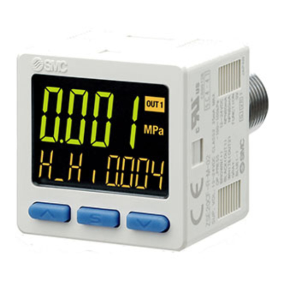
3 Name and function of product parts
2
,
Operation light: Displays the switch operating condition.
LCD display: Displays the current status of pressure, setting mode,
selected display units and error code.
4 types of display can be selected for the main display:
Single colour of constant red or green; or switching from
red to green or green to red corresponding to the output.
The indication for the sub display is orange.
Main display:
Displays pressure measurement values and error
codes. (2-colour display)
o
C
Sub display (left):
Displays items. (Orange)
Sub display (right): Displays set values, peak and bottom values.
(Orange)
UP button: Increases mode and ON/OFF set values.
DOWN button: Decreases mode and ON/OFF set values.
SET button: Press this button to change mode and to confirm
settings.
Unit display: Indicates the units currently selected (only for kPa and
MPa).
4 Installation
4.1 Installation
A2(L)
B2(L)
URJ
TSJ
Do not install the product unless the safety instructions have been read
G1/4
Rc1/8
1/4
1/4
and understood.
4.1.1 Mounting
• Mount the optional bracket and panel mount adapter to the pressure
switch.
48 g
47 g
54 g
46 g
• When the pressure switch is to be mounted in a place where water
and dust splashes occur, insert a tube into the atmospheric vent port
74 g
65 g
81 g
72 g
of the pressure switch (refer to "Tube attachment").
+39 g
4.1.2 Mounting with bracket
• Mount the bracket to the body with mounting screws (Self tapping
1 x 10
-10
Pa •
3
/s
screws: Nominal size 3 x 8L (2 pcs)), then set the body to the
m
3
/s
specified position.
∗: Tighten the bracket mounting screws to a torque of 0.5 ±0.05 N•m.
Self-tapping screws are used and should not be re-used several times.
2
(AWG26)
• Rear Piping
1.0 mm
• Bracket A (Part No.: ZS-46-A1)
φ3.5
• Bottom Piping
• Bracket C (Part No.: ZS-46-E)
4.1.3 Mounting with panel mount adapter
• Rear Piping
• Mount part (a) to the front of the body and fix it. Then insert the body
with (a) into the panel until (a) comes into contact with the panel front
surface. Next, mount part (b) to the body from the rear and insert it
until (b) comes into contact with the panel.
• Panel mount adapter (Part No.: ZS-46-B)
Panel mount adapter + Front protective cover (Part No.: ZS-46-D)
∗: The panel mount adapter can be rotated through 90 degrees for mounting.
Warning
Page 1 of 3
Advertisement

Related Manuals for SMC Networks ZSE20C Series


Summary of Contents for SMC Networks ZSE20C Series
- Page 1 Z_ISE20C-TF2Z061EN 2 Specifications 2 Specifications (continued) 4 Installation ORIGINAL INSTRUCTIONS 2.1 General specifications 2.2 Piping / Weight specifications 4.1 Installation Warning Product No. 02(L) N02(L) F02(L) C01(L) A2(L) B2(L) ZSE20C ZSE20CF ISE20C ISE20CH Instruction Manual Product No. (Vacuum (Compound (Positive (Positive Do not install the product unless the safety instructions have been read Port size...
- Page 2 Z_ISE20C-TF2Z061EN 4 Installation (continued) 4 Installation (continued) 5 Settings 6 3 step Setting mode • Bottom Piping 4.3.1 Tube attachment Power is supplied. [3 step setting mode (hysteresis mode)] In the 3 step setting mode, the set value (P_1 or n_1, P_2 or n_2) and •...
- Page 3 Z_ISE20C-TF2Z061EN 8 Function Selection mode 9 Other Settings 14 Product disposal In measurement mode, press the button between 3 and 5 seconds, • Snap shot function This product shall not be disposed of as municipal waste. Check your to display [F 0]. Select to display the function to be changed [F□□]. The current pressure value can be stored to the switch output ON/OFF local regulations and guidelines to dispose of this product correctly, in Press and hold the...
Need help?
Do you have a question about the ZSE20C Series and is the answer not in the manual?
Questions and answers