
Related Manuals for ADLINK Technology MCM-100


Summary of Contents for ADLINK Technology MCM-100
- Page 1 MCM-100/102 Edge IoT Platform for Machine Condition Monitoring User’s Manual Manual Rev.: Revision Date: June 18, 2019 Part No: 50-1Z298-1000 Leading EDGE COMPUTING...
- Page 2 Leading EDGE COMPUTING Revision History Revision Release Date Description of Change(s) June 18, 2019 Initial Release...
- Page 3 MCM-100/102 Preface Copyright 2019 ADLINK Technology Inc. This document contains proprietary information protected by copy- right. All rights are reserved. No part of this manual may be repro- duced by any mechanical, electronic, or other means in any form without prior written permission of the manufacturer.
- Page 4 Leading EDGE COMPUTING Battery Labels (for products with battery) California Proposition 65 Warning WARNING: This product can expose you to chemicals including acrylamide, arsenic, benzene, cadmium, Tris(1,3-dichloro-2-propyl) phosphate (TDCPP), 1,4- Dioxane, formaldehyde, lead, DEHP, styrene, DINP, BBP, PVC, and vinyl materials, which are known to the State of California to cause cancer, and acrylamide, benzene, cadmium, lead, mercury, phthalates, toluene, DEHP, DIDP, DnHP, DBP, BBP, PVC, and vinyl materials, which are known to the State of California to cause...
- Page 5 MCM-100/102 Information to prevent minor physical injury, component dam- age, data loss, and/or program corruption when trying to com- plete a task. CAUTION: Information to prevent serious physical injury, component damage, data loss, and/or program corruption when trying to complete a specific task.
- Page 6 Leading EDGE COMPUTING This page intentionally left blank. Preface...
-
Page 7: Table Of Contents
MCM-100/102 Table of Contents Preface ..................iii List of Tables................ xiii List of Figures ............... xv 1 Introduction ................ 1 Features................1 Specifications............... 2 1.2.1 General............... 2 1.2.2 I/O................3 1.2.3 Power Consumption ........... 6 Mechanical Drawings............8 I/O Connectors..............10 1.4.1... - Page 8 Leading EDGE COMPUTING Cooling Considerations............23 Installing Mini-PCIe WiFi Module (Optional) ...... 24 3 Driver & Application Installation ........29 Installing the Chipset Driver ..........29 Installing the Graphics Driver..........30 Installing the Ethernet Driver..........30 Installing the USB 3.0 Driver..........31 Installing the I/O Controller Driver........
- Page 9 MCM-100/102 External Digital Triggering ..........42 Trigger Modes ............... 43 Delay-Trigger Acquisition (no retrigger) ......44 Middle-Trigger Acquisition ..........45 Gated Trigger ..............45 Post-Trigger or Delay-Trigger Acquisition with Re-Trigger ............. 46 Programmable Function I/O..........46 4.3.1 Static Digital Input/Output......... 46 4.3.2...
- Page 10 Leading EDGE COMPUTING A.2.2 Graphics Configuration ..........56 GTT Size ............... 56 Aperture Size ..............56 DVMT Pre-Allocated ............. 57 DVMT Total Gfx Mem ........... 57 A.2.3 Onboard Device Configuration ......... 57 COM1 Control ............... 57 COM2 Control ............... 57 HSUART ...............
- Page 11 MCM-100/102 A.2.8 Network Stack Configuration ........69 Network Stack ............... 69 A.2.9 System Management..........70 Flags ................74 Power Up ..............75 A.2.10 Miscellaneous............76 OS Selection ..............76 A.2.11 Intel® I210 Gigabit Network Connection ....77 Blink LEDs ..............77 A.2.12...
- Page 12 Leading EDGE COMPUTING Restore User Defaults ..........83 Launch EFI Shell from filesystem device ...... 83 B Appendix: Functional Information ........85 AI and GPI/O Functional Layout ........86 Internal I/O Connectors............87 B.2.1 Internal HSUART Interface Wafer ......89 B.2.2 USIM Port ..............
-
Page 13: List Of Tables
DB-9P COM Port Pin Assignment ......14 Table 1-4: Gigabit Ethernet Port LED Function ......16 Table 4-1: Signal Source-Card Configuration......35 Table 4-2: MCM-100/102 Input Ranges ........37 Table B-1: Internal I/O Legend........... 89 Table B-2: HSUART Interface Wafer Pin Definitions ....89 Table B-3: USB2.0 Interface Wafer Pin Definitions.... - Page 14 Leading EDGE COMPUTING This page intentionally left blank. List of Tables...
-
Page 15: List Of Figures
Figure 1-5: (Left) Side View ............10 Figure 1-6: Front Panel I/O ............10 Figure 1-7: MCM-100 Right Side Panel I/O ........ 11 Figure 1-8: MCM-102 Right Side Panel I/O ........ 11 Figure 1-9: Left Side Panel I/O ........... 12 Figure 1-10: DB-9P COM Port ............ - Page 16 Leading EDGE COMPUTING This page intentionally left blank. List of Figures...
-
Page 17: Introduction
MCM-100/102 Introduction ADLINK's MCM-100/102 features built-in vibration signal acquisi- tion, with 2 or 4 BNC for analog input. The machine condition mon- itoring edge platform highlights around-the-clock continuous data collection and vibration measurement with maximized precision and sampling rates for rotating machinery and equipment. Com-... -
Page 18: Specifications
Leading EDGE COMPUTING 2X Digital I/O by terminal block 1x DP, 2x GbE, 2x COM(RS232/RS422/RS485), 2x USB 2.0, 2x USB 3.0 DIN rail mounting, wall mounting 1.2 Specifications 1.2.1 General System Core Intel® Atom x7-E3950 Processor Chipset Video 1 x DisplayPort 1.2 (supports DP++) 4 GB DDR3L 1600 MHz SODIMM module... -
Page 19: I/O
MCM-100/102 Humidity Approx. 95% @ 40°C (non-condensing) Vibration Operating, 5 Grms, 5-500 Hz, 3 axes (w/ mSATA) Contact +/-4 KV and Air +/-8 KV Shock Operating 100 G, half sine 11 ms duration w/ mSATA CE & FCC Class A (EN61000-6-4/EN61000-6-2) 1.2.2... - Page 20 Leading EDGE COMPUTING CMRR AC (20Hz to 1kHz) 60 dB Bandwidth -3dB bandwidth 0.49 x fs (where fs = sampling rate) AC cut-off frequency (-3dB) 0.4 Hz AC cut-off frequency (-0.1dB) 2.4 Hz Digital I/O Channels 2 programmable function I/O Compatibility 3.3V / TTL (single-ended) Initial status...
- Page 21 MCM-100/102 DC Accuracy @25°C Typical Max. Offset Error (mV) ±0.15mV ±0.3mV Gain Error (%) ±0.15mV ±0.3% AC Dynamic Performance (typical, 25°C), THD, THD+N (Vin = 8.9 Vpk) Input Configuration Input Signal Frequency (fin) THD THD+N 20Hz to 20kHz -94dB -91 dB Differential 20Hz to 46.4kHz...
-
Page 22: Power Consumption
Leading EDGE COMPUTING Dynamic Range (Vin = -60 dBFS) Input Signal Frequency (f Dynamic Range 1kHz 100 dB SFDR (Vin = -1 dBFS) Input Signal Frequency (f SFDR 1kHz 104 dB 1.2.3 Power Consumption Status Power Condition Connected I/O In shutdown mode with DC Keyboard and Power off 3.6W... - Page 23 MCM-100/102 Status Power Condition Connected I/O USB3.0 0.9A *2 full load With voltage de-rating at high USB2.0 0.5A*2 environmental temperature USB port full load full load Analog Input receiving data. COM port Burn-in test 8.1 full running. loopback AI functioning...
-
Page 24: Mechanical Drawings
Leading EDGE COMPUTING 1.3 Mechanical Drawings All dimensions shown are in millimeters (mm) unless otherwise stated. NOTE: NOTE: Figure 1-1: Top View (MCM-100) Figure 1-2: Front View Introduction... -
Page 25: Figure 1-3: Mcm-100 (Right) Side View
MCM-100/102 Figure 1-3: MCM-100 (Right) Side View Figure 1-4: MCM-102 (Right) Side View Introduction... -
Page 26: I/O Connectors
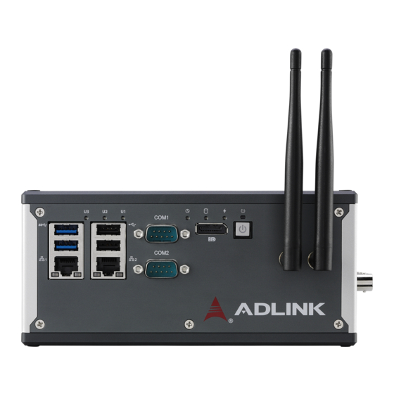
Leading EDGE COMPUTING Figure 1-5: (Left) Side View 1.4 I/O Connectors The following lists I/O connectors of the MCM-100/102, as labeled. Figure 1-6: Front Panel I/O Introduction... -
Page 27: Figure 1-7: Mcm-100 Right Side Panel I/O
MCM-100/102 Figure 1-7: MCM-100 Right Side Panel I/O Figure 1-8: MCM-102 Right Side Panel I/O Introduction... -
Page 28: Power Button
Leading EDGE COMPUTING Figure 1-9: Left Side Panel I/O Power button Reset button Antenna port DisplayPort connector LED operation indicators (x3) LED user-defined indicators (x3) DB-9P COM ports (x2) GbE ports (x2) USB2.0 ports (x2) ... -
Page 29: Reset Button
MCM-100/102 1.4.2 Reset Button The reset button executes hard reset for the MCM-100/102. 1.4.3 DisplayPort Connector One DisplayPort connector on the front panel supports the DP1.2 standard specification, and can connect to VGA, DVI, HDMI, and Display Port monitors via DisplayPort to VGA adapter cable, Dis- playPort to DVI adapter cable, or DisplayPort to HDMI adapter cable and Display Port cable, with DP1.2 support for resolutions... -
Page 30: Led Indicators
Leading EDGE COMPUTING 1.4.4 LED Indicators In addition to the LED of the power button, three LEDs on the front panel indicate the following operations. Indicator Color Description Indicates watchdog timer status. Flashes when Watchdog (WDT) Yellow watchdog timer starts, and when timer is expired, system will auto-reboots. -
Page 31: Dual Gigabit Ethernet Ports
MCM-100/102 Signal TXD422+ 485+ RXD422+ DTR# RXD422- DSR# RTS# CTS# Table 1-3: DB-9P COM Port Pin Assignment 1.4.6 Dual Gigabit Ethernet Ports Two Gigabit Ethernet ports on the front panel support the Intel i210IT GbE controller, which provides: IEEE 802.3az Energy Efficient Ethernet ... -
Page 32: Usb 3.0 Port
Leading EDGE COMPUTING LED Color Status Description Ethernet port is disconnected Ethernet port is connected with no Active/Link Yellow activity Ethernet port is connected and Flashing active 10 Mbps Green/ Speed Green 100 Mbps Yellow Yellow 1000 Mbps Table 1-4: Gigabit Ethernet Port LED Function 1.4.7 USB 3.0 Port The USB 3.0 port supports Type A connection, compatible with... -
Page 33: 4-Pin Gpi/O W/ Dgnd Connector
MCM-100/102 1.4.9 4-pin GPI/O w/ DGND Connector The 4-pin removable spring terminal connector provides connec- tion for GPI/O0, GPI/O1, and two DGND signals GPIO0 DGND GPIO1 DGND Figure 1-12: 4-pin GPI/O w/ DGND Connector 1.4.10 DC Power Supply Connector Located on the left side panel. - Page 34 Leading EDGE COMPUTING This page intentionally left blank. Introduction...
-
Page 35: Getting Started
Output current: 4.2 to 0.7A minimum Tma: 50°C min. The DC power input connector of the MCM-100/102 utilizes V+, V- and chassis ground pins, and accepts input voltage as shown pre- viously. 2.3 DIN Rail Mounting The MCM-100/102 controller is shipped with wall-mounting brack- ets and accessory screws, with mounting procedures as follows. - Page 36 Leading EDGE COMPUTING 2. Use the 2 included M4-F head screws to fix the DIN rail bracket to the chassis, according to the spacing dimen- sions of the screw holes and brackets, as shown. Getting Started...
- Page 37 MCM-100/102 161.58 150.38 134.3 118.22 113.95 60.6 Getting Started...
-
Page 38: Wall Mounting
Leading EDGE COMPUTING 2.4 Wall Mounting The MCM-100/102 ships with wall-mounting brackets and acces- sory screws, with mounting procedures as follows. While configuration shown may indicate otherwise, due to the presence of antenna ports, for safety, the device should ONLY... -
Page 39: Cooling Considerations
MCM-100/102 152.4 2.5 Cooling Considerations Heat-generating components of the MCM-100/102 (such as CPU and PCH) are all situated on the left side of the system. These components directly contact the heat sink via thermal pads and dissipate heat generated by the components. To maximize effi- ciency of heat dissipation, maintain a minimum of 2 inches (5cm) clearance on the top of the MCM-100/102. -
Page 40: Installing Mini-Pcie Wifi Module (Optional)
Leading EDGE COMPUTING 2.6 Installing Mini-PCIe WiFi Module (Optional) 1. Remove all screws and internal mini-USB connector, separating the MCM-100/102 into five parts. 2. Fix bracket with two screws. Getting Started... - Page 41 MCM-100/102 3. Insert mini-PCIe WiFi module into the carriage at an angle. 4. Depress the module until seated and fix with two M2.5- P-head-L5 screws. Getting Started...
- Page 42 Leading EDGE COMPUTING 5. Connect SMA-to-IPEX cable to WiFi module. 6. Remove plastic cap and mount SMA connectors. Getting Started...
- Page 43 MCM-100/102 7. Reassemble all parts and connect mini-USB, fixing the chassis with screws. 8. Connect antenna to SMA connector Getting Started...
- Page 44 Leading EDGE COMPUTING This page intentionally left blank. Getting Started...
-
Page 45: Driver & Application Installation
MCM-100/102 Driver & Application Installation After installing the operating system, all related drivers must be installed for the system to function properly. This section describes the drivers needed for Windows operating systems and the procedures to install them. For other OS support, please contact ADLINK for further information. -
Page 46: Installing The Graphics Driver
Leading EDGE COMPUTING To install the chipset driver for the MCM-100/102 1. Close any running applications. 2. From ADLINK's website, download Windows 10 IoT Enterprise drivers for the MCM-100/102. 3. Execute Setup.exe and follow onscreen instructions to complete the setup. -
Page 47: Installing The Usb 3.0 Driver
4. After installation is complete, reboot the system. 3.6 Installing the SEMA Utility, WDT and DI/O Drivers The MCM-100/102 supports ADLINK Smart Embedded Manage- ment Utility with features as follows. System Health for real time CPU, system temperature, total/ ... -
Page 48: Installing Ai And Di/O Drivers
To install the SEMA utility, WDT and DI/O drivers: 1. Close any running applications. From ADLINK's website, download Windows 10 IoT Enterprise drivers for the MCM-100/102. 2. Execute Setup.exe and follow onscreen instructions to complete the setup. After installation is complete, reboot the system. -
Page 49: Daq-Lview Plus
MCM-100/102 DAQ-LVIEW Plus The task-oriented SDK supports LVOOP VI and Polymorphic VI for LabVIEW. Download DAQ-LVIEW Plus from the ADLINK website. Driver & Application Installation... - Page 50 Leading EDGE COMPUTING This page intentionally left blank. Driver & Application Installation...
-
Page 51: Operation
MCM-100/102 Operation Operation of the MCM-100/102 is described here to assist in configuration and programming of the module. Functions addressed include analog input and GPI/O. 4.1 Analog Input 4.1.1 Analog Input Front End Configuration Diff input Differential/ Psuedo- 24 Bit ADC... -
Page 52: Input Coupling
The excitation current is 2 mA for the IEPE sensors, with DC volt- age offset generated because of the excitation current and sensor impedance. When enabling IEPE current sources, the MCM-100/ 102 automatically sets input configuration to AC coupling. Constant... -
Page 53: Ai Data Format
After A/D conversion, the A/D data is buffered in a Data FIFO, for transfer to memory for further processing. Transfer characteristics of various input ranges of the MCM-100/102 are as follows, with data format 2’s complement. Bipolar Analog Description... -
Page 54: Data Transfer
The stopband of the ADC provides 100dB attenua- tion of frequencies that begin just beyond the passband and con- tinue out to ADC over-sampling rate. The MCM-100/102 provides an anti-aliasing, low-pass, simple RC filter in front of the ADC inputs to limit possible high amplitude out-of-band signals and noise. -
Page 55: Figure 4-3: Input Frequency Response For High Resolution Mode
MCM-100/102 −3dB Bandwidth (Fs = 51.2KS/s) X: 25 −5 Y: −2.058 −10 −15 −20 −25 −30 −35 Input Signal Frequency (kHz) Figure 4-3: Input Frequency Response for High Resolution Mode Operation... -
Page 56: Triggering
Input Signal Frequency (kHz) Figure 4-4: Input Frequency Response for High Speed Mode 4.2 Triggering The MCM-100/102 supports flexible trigger sources and trigger modes for analog input functionality. The trigger source can origi- nate with software command, external analog, or external digital signal in continuous analog input mode. -
Page 57: External Analog Trigger
MCM-100/102 External Analog Trigger The analog multiplexer can select one input channel as the analog trigger source. That is, one of 4 input channels can be selected as the analog trigger source. An external analog trigger occurs when the analog trigger signal crosses above (above high) or below (below low) the pre-defined voltage level. -
Page 58: External Digital Triggering
Leading EDGE COMPUTING Figure 4-6: Above-High Analog Triggering External Digital Triggering An external digital trigger occurs when a rising or falling edge is detected on the digital signal connected to the GPI/O pin. Trigger polarity can be programmed using ADLINK software drivers. Signal level of the external digital trigger signals should be 3/ 3V/TTL-compatible, with a minimum pulse of 20ns. -
Page 59: Trigger Modes
MCM-100/102 Trigger Modes Analog input supports post, delay, middle, gate, post trigger with retrigger, and delay trigger with retrigger modes. Post-Trigger Acquisition Mode (no retrigger) Post-trigger acquisition is indicated in applications where data is to be collected after a trigger event, as shown. -
Page 60: Delay-Trigger Acquisition (No Retrigger)
Leading EDGE COMPUTING Trigger Event Occurs Acquisition stop Operation start Begin to transfer data to Acquisition start system Time Trigger Data N samples This data is Only acquired N discarded. samples will be transferred back to system. Figure 4-9: Pre-trigger Mode Operation (valid trigger only) The trigger event occurs after the specified amount of data has been acquired. -
Page 61: Middle-Trigger Acquisition
MCM-100/102 Acquisition stop Trigger Event Begin to transfer data Operation Occurs Acquisition start to system start Delay Time Time Trigger Data N samples Figure 4-11: Delay-Trigger Mode Operation Middle-Trigger Acquisition Middle-trigger acquisition is indicated when data is to be collected before and after the trigger event. -
Page 62: Post-Trigger Or Delay-Trigger Acquisition With Re-Trigger
The process repeats until the specified amount of re- trigger signals is detected. 4.3 Programmable Function I/O The MCM-100/102 supports powerful programmable I/O function provided by an FPGA chip, configurable as static digital input/out- put, 32-bit frequency counters, pulse output, synchronization sam- ple clock IN, and trigger IN. -
Page 63: Pulse Output
To synch multiple devices, the GPI/O can be programmed as external sample clock input, with the same trigger signal and external sample clock applicable to multiple MCM-100/102s to achieve more than 4 channel synchronization without phase delay. Note the synchronization sample clock must be continuous, with valid frequency range from 1 kHz to 128 kHz. - Page 64 Leading EDGE COMPUTING This page intentionally left blank. Operation...
-
Page 65: Calibration
Since measurement errors may vary depending on time and tem- perature, it is recommended that the MCM-100/102 module be calibrated in the existing testing environment, as follows. 5.2 Auto-Calibration The MCM-100/102 module should be warmed up for at least 15 minutes before initiating auto-calibration. NOTE: NOTE:... -
Page 66: Saving Calibration Constants
Leading EDGE COMPUTING 5.3 Saving Calibration Constants Factory-calibrated constants are permanently stored in a bank of the onboard EEPROM and cannot be modified. When the device is recalibrated through auto-calibration, the software stores the new constants in a user-configurable section of the EEPROM. To restore original factory calibration settings, the software can copy the factory-calibrated constants to the user-configurable section of the EEPROM. -
Page 67: A Appendix: Bios Setup
MCM-100/102. The BIOS setup program includes menus for configuring settings and enabling features of the MCM-100/102. Most users do not need to use the BIOS setup program, as the MCM-100/102 ships with default settings that work well for most configurations. -
Page 68: Main
Leading EDGE COMPUTING A.1 Main A.1.1 BIOS Information Shows current system BIOS core version, BIOS version and Board version. A.1.2 System Time/System Date Changes system time and date. Highlight System Time or System Date using the up or down <Arrow> keys. Enter new values using the keyboard then <Enter>. -
Page 69: Board Information
MCM-100/102 The time is in 24-hour format, for example, 5:30 A.M. appears as 05:30:00, and 5:30 P.M. as 17:30:00. NOTE: NOTE: A.1.3 Board Information Displays serial number, manufacturing date, last repair date, and MAC ID. As well, Runtime Statistics are listed, including total run- time, current runtime, power cycles, boot cycles, and boot reason. -
Page 70: Advanced
Leading EDGE COMPUTING A.2 Advanced Setting incorrect or conflicting values in Advanced BIOS Setup may cause system malfunction. CAUTION: BIOS Setup... -
Page 71: Cpu Configuration
MCM-100/102 A.2.1 CPU Configuration Active Processor Cores Number of cores to enable in each processor package. Intel Virtualization Technology When enabled, allows a VMM to utilize the additional hardware capabilities provided by Vanderpool Technology VT-d Enables/disables CPU VT-d Turbo Mode Enables/disables Turbo Mode. -
Page 72: Critical Trip Point
Leading EDGE COMPUTING Critical Trip Point Temperature threshold of the Critical Trip Point. Passive Cooling Trip Point Temperature threshold of the Passive Cooling Trip Point. A.2.2 Graphics Configuration GTT Size Sets GTT size Aperture Size Sets aperture size BIOS Setup... -
Page 73: Dvmt Pre-Allocated
MCM-100/102 DVMT Pre-Allocated Sets size of DVMT 5.0 pre-allocated (fixed) graphics memory used by internal graphics device DVMT Total Gfx Mem Sets size of DVMT5.0 total graphic memory used by internal graphics device A.2.3 Onboard Device Configuration COM1 Control Selects COM1 mode from among RS232, RS422, and RS485. -
Page 74: Hsuart
Leading EDGE COMPUTING HSUART Enables/disables LPSS HSUART support. LAN #1 (Intel I210) Enables/disables LAN device #1. LAN #2 (Intel I210) Enables/disables LAN device #2. Realtek Audio Support Enables/disables Realtek audio device. Serial Console Redirection BIOS Setup... -
Page 75: Console Redirection
MCM-100/102 COM 1 Console Redirection Enables/Disables COM 1 console redirection. Console Redirection Settings (COM 1) Terminal Type Emulation: ANSI: Extended ASCII char set. VT100: ASCII char set. VT100+: Extends VT100 to support color, function keys, etc. VT-UTF8: Uses UTF8 encoding to map Unicode chars onto 1 or more bytes. - Page 76 Leading EDGE COMPUTING Bits per second Selects serial port transmission speed, which must be matched on the other side, where long or noisy lines may require lower speeds. Data Bits Number of data bits Parity Parity bit can be sent with data bits to detect transmission errors, where Even: parity bit is 0 if the number of 1's in the data bits is even Odd: parity bit is 0 if number of 1's in the data bits is odd.
- Page 77 MCM-100/102 Resolution 100x31 Enables/disables extended terminal resolution Legacy OS Redirection Resolution In legacy OS, the number of rows and columns supporting redi- rection Putty KeyPad Selects FunctionKey and KeyPad on PuTTY Redirection After BIOS Post When Bootloader is selected, Legacy Console Redirection is disabled before booting to legacy OS.
-
Page 78: Console Redirection
Leading EDGE COMPUTING COM 2 Console Redirection Enables/Disables COM 2 console redirection. Console Redirection Settings (COM 2) Terminal Type Emulation: ANSI: Extended ASCII char set. VT100: ASCII char set. VT100+: Extends VT100 to support color, function keys, etc. VT-UTF8: Uses UTF8 encoding to map Unicode chars onto 1 or more bytes. - Page 79 MCM-100/102 Bits per second Selects serial port transmission speed, which must be matched on the other side, where long or noisy lines may require lower speeds. Data Bits Number of data bits Parity Parity bit can be sent with data bits to detect transmission...
-
Page 80: Advanced Power Management
Leading EDGE COMPUTING Resolution 100x31 Enables/disables extended terminal resolution Legacy OS Redirection Resolution In legacy OS, the number of rows and columns supporting redi- rection Putty KeyPad Selects FunctionKey and KeyPad on PuTTY Redirection After BIOS Post When Bootloader is selected, Legacy Console Redirection is disabled before booting to legacy OS. -
Page 81: Power Supply Unit
MCM-100/102 Power Supply Unit ATX: OS will turn off system power when shutdown, where AT mode does not support S3 & S4. State After G3 Specifies state to enter when power is re-applied after a power failure (G3 state). RTC Wake system from S5... -
Page 82: Usb Configuration
Leading EDGE COMPUTING A.2.5 USB Configuration XHCI Hand-off A workaround for OS without XHCI handoff support, where XHCI ownership change should be claimed by the XHCI driver. USB Mass Storage Driver Support Enables/disables USB mass storage driver support. USB transfer time-out Timeout value for Control, Bulk, and Interrupt transfers. -
Page 83: Device Power-Up Delay
MCM-100/102 Device power-up delay Maximum time the device will take before reporting to the Host Controller, where Auto uses default value, for a Root port 100 ms, and for a Hub port the delay is taken from the Hub descriptor. -
Page 84: Tpm Configuration
Leading EDGE COMPUTING A.2.7 TPM Configuration Security Device Support Enables/disables BIOS support for security device, when enabled, OS will not show the security device, and TCG EFI protocol and INT1A interface will not be available. BIOS Setup... -
Page 85: Network Stack Configuration
MCM-100/102 A.2.8 Network Stack Configuration Network Stack Enables/disables UEFI network stack BIOS Setup... -
Page 86: System Management
Leading EDGE COMPUTING A.2.9 System Management Shows SEMA firmware and bootloader versions and build dates. BIOS Setup... - Page 87 MCM-100/102 SEMA Features Shows features supported by the SEMA version. BIOS Setup...
- Page 88 Leading EDGE COMPUTING Temperatures Shows current CPU temperature, and current, startup, mini- mum, and maximum board temperatures. BIOS Setup...
- Page 89 MCM-100/102 Power Consumption Shows current input current and power, as well as system volt- ages. BIOS Setup...
-
Page 90: Flags
Leading EDGE COMPUTING Flags Shows BMC flags with exception codes. BIOS Setup... -
Page 91: Power Up
MCM-100/102 Power Up Lists Power-Up Watchdog status. BIOS Setup... -
Page 92: Miscellaneous
Leading EDGE COMPUTING A.2.10 Miscellaneous OS Selection Allows selection of active OS. BIOS Setup... -
Page 93: Intel® I210 Gigabit Network Connection
MCM-100/102 A.2.11 Intel® I210 Gigabit Network Connection Blink LEDs Identifies the physical network port by flashing the associated LED. BIOS Setup... -
Page 94: Nic Configuration
Leading EDGE COMPUTING A.2.12 NIC Configuration Link Speed Specifies the port speed used for the selected boot protocol. Wake On LAN Enables server power-up using an in-band magic packet. BIOS Setup... -
Page 95: Security
MCM-100/102 A.3 Security If only the Administrator’s password is set, only access to Setup is limited and authorization requested only when enter- ing Setup. If only the User’s password is set, a password must NOTE: NOTE: be entered to boot or enter setup. In Setup the user has Admin- istrator rights. -
Page 96: Secure Boot
Leading EDGE COMPUTING A.3.1 Secure Boot Shows System Mode and Secure Boot status. Secure Boot is activated when Platform Key (PK) is enrolled, where System Mode is User/Deployed, and CSM function is disabled. NOTE: NOTE: BIOS Setup... -
Page 97: Boot
MCM-100/102 A.4 Boot Setup Prompt Timeout Number of seconds to wait for setup activation key, with 65535(0xFFFF) indicating infinite wait. Bootup NumLock State Sets keyboard NumLock status Quiet Boot Enables/disables Quiet Boot option Fast Boot Enables/disables boot with the minimal device initialization required to launch active boot option, with no effect on BBS boot options. -
Page 98: Boot Option Priorities
Leading EDGE COMPUTING Sets number of seconds to wait for setup activation key. Boot Option Priorities Specifies the priority of boot devices, with all installed boot devices detected during POST and displayed, where selecting Boot Option # specifies the desired boot device. A.5 Save &... -
Page 99: Save Changes And Reset
MCM-100/102 Save Changes and Reset Resets the system after saving changes. Discard Changes and Reset Resets system setup without saving any changes. Save Changes Saves changes to any setup options. Discard Changes Discards changes to any of the setup options. - Page 100 Leading EDGE COMPUTING This page intentionally left blank. BIOS Setup...
-
Page 101: B Appendix: Functional Information
Wafer Mini PCIe USIM Card v1.2 Slot 1 SATA III 0 mSATA PCIe X1 & USB2.0 Mini PCIe connector v1.2 Slot 2 SATA III 1 Internal SATA USB2.0 x1 connector USB-2405 Figure B-1: MCM-100/102 System Functional Block Diagram Functional Information... -
Page 102: Ai And Gpi/O Functional Layout
I2C Interface 3.3V Supply GPIO Circuit USB BUS +5V Supply 2-CH GPIO DI, DO, Power DDR2 SDRAM GPIO Counter, circuit 3.3 2.5 1.2V PWM OUT, DATA Supply Trigger IN Figure B-2: MCM-100/102 AI and GPI/O Functional Block Diagram Functional Information... -
Page 103: Internal I/O Connectors
MCM-100/102 B.2 Internal I/O Connectors Figure B-3: Mainboard Top View Functional Information... -
Page 104: Figure B-4: Mainboard Underside View
Leading EDGE COMPUTING Figure B-4: Mainboard Underside View USB2.0 internal dongle (CN21)* RTC Battery Header (CN_BAT) Internal Speaker Wafer (Optional) (CN8) Internal MIC-IN & HP-OUT Wafer (Optional) (CN6) Extended reset wafer (CN27) Internal I2C Interface Wafer (CN20) Extended power wafer (CN26) Internal SATA Interface Wafer (CN32) Micro SD card socket (CN31) USIM slot (CN15) -
Page 105: Internal Hsuart Interface Wafer
Signal +3.3V SOC_UART1_RX_CON SOC_UART1_TX_CON SOC_UART1_CTS_CON-L SOC_UART1_RTS_CON-L Table B-2: HSUART Interface Wafer Pin Definitions B.2.2 USIM Port Use of 3G/4G mini-PCIe module requires a SIM card for communi- cation with telecom operator. The MCM-100/102 provides a USIM Functional Information... -
Page 106: Internal Usb2.0 Interface Wafer
Leading EDGE COMPUTING port connected to the mini-PCIe connector, with which a SIM card and 3G/4G mini-PCIe module can be installed to facilitate 3G/4G communication. B.2.3 Internal USB2.0 Interface Wafer Signal SOC_USB2_D6_P SOC_USB2_D6_N +3.3V USB2_WAFER-L Table B-3: USB2.0 Interface Wafer Pin Definitions B.2.4 Internal I2C Interface Wafer I2C and +3.3V/+5V power by this connector with cable. -
Page 107: Clear Cmos Jumper
Table B-4: Internal I2C Interface Wafer Pin Definitions B.2.5 Clear CMOS Jumper Under conditions in which the MCM-100/102 fails to boot, clearing the BIOS content stored in CMOS and restoring the default set- tings may be effective. To clear CMOS, short Pin 1 and Pin 2 of CN24 and remove the jumper, after which the CMOS will be restored to factory default settings. -
Page 108: Internal Sata Interface Wafer
Leading EDGE COMPUTING Signal Table B-6: +5V GPS Antenna Power Connector Pin Definition B.2.7 Internal SATA Interface Wafer Reserved for extended 2.5” SSD, providing SATA signal and +3.3V/+5V power with cable. Signal Signal SOC_SATA_TX1_P_C SOC_SATA_TX1_N_C Table B-7: SATA Wafer Pin Definition Functional Information... -
Page 109: Extended Power Wafer
MCM-100/102 Signal Signal SOC_SATA_RX1_N_C SOC_SATA_RX1_P_C +3.3V +3.3V +3.3V Table B-7: SATA Wafer Pin Definition B.2.8 Extended Power Wafer Provides internal connectors for the power button. Signal PWR_BTN_CN-L Table B-8: Extended Power Header Connector Pin Definition Functional Information... -
Page 110: Internal I2C Interface Wafer
Leading EDGE COMPUTING B.2.9 Internal I2C Interface Wafer Provides the I2C signal and +3.3V power with cable. Signal +3.3V SOC_I2C0_DAT SOC_I2C0_CLK SOC_I2C0_INT Table B-9: I2C Box Header Connector Pin Definition B.2.10 Extended Reset Wafer Provides internal connectors for the reset button. Signal RESET_BTN_CN-L Table B-10: Extended Reset Header Connector Pin Definition... -
Page 111: Rtc Battery Header
MCM-100/102 B.2.11 RTC Battery Header Links to the 3V coin battery pack for system RTC function. Signal P_+3V3_VBAT Table B-11: RTC Battery Connector Pin Definition B.2.12 Internal Speaker Wafer (Optional) Provides the audio speaker signal, supporting 2x 2W8Ω speaker. Signal... -
Page 112: Internal Mic-In & Hp-Out Wafer (Optional)
Leading EDGE COMPUTING B.2.13 Internal MIC-IN & HP-OUT Wafer (Optional) Provides MIC-IN and HP-OUT signals with cable. Signal EX_MIC_CN HP_CN_L HP_CN_R AGND_AUDIO Table B-13: MIC-IN & HP-OUT Wafer Pin Definition Functional Information... -
Page 113: Important Safety Instructions
MCM-100 Important Safety Instructions For user safety, please read and follow all instructions, Warnings, Cautions, and Notes marked in this manual and on the associated device before handling/operating the device, to avoid injury or damage. S'il vous plaît prêter attention stricte à tous les avertissements et mises en garde figurant sur l'appareil , pour éviter des blessures... - Page 114 Leading EDGE COMPUTING Never attempt to repair the device, which should only be serviced by qualified technical personnel using suitable tools A Lithium-type battery may be provided for uninterrupted backup or emergency power. Risk of explosion if battery is replaced with one of an incorrect type;...
- Page 115 MCM-100 BURN HAZARD Touching this surface could result in bodily injury. To reduce risk, allow the surface to cool before touching. RISQUE DE BRÛLURES Ne touchez pas cette surface, cela pourrait entraîner des blessures. Pour éviter tout danger, laissez la surface refroidir avant de la toucher.
- Page 116 Leading EDGE COMPUTING This page intentionally left blank. Important Safety Instructions...
-
Page 117: Getting Service
San Jose, CA 95138, USA Tel: +1-408-360-0200 Toll Free: +1-800-966-5200 (USA only) Fax: +1-408-360-0222 Email: info@adlinktech.com ADLINK Technology (China) Co., Ltd. 300 Fang Chun Rd., Zhangjiang Hi-Tech Park Pudong New Area, Shanghai, 201203 China Tel: +86-21-5132-8988 Fax: +86-21-5132-3588 Email: market@adlinktech.com...
Need help?
Do you have a question about the MCM-100 and is the answer not in the manual?
Questions and answers