
Related Manuals for ADLINK Technology NuPRO-770 Series


Summary of Contents for ADLINK Technology NuPRO-770 Series
- Page 1 NuPRO-770 Series Full Size Socket-370 PICMG Industrial SBC User’s Guide Recycled Paper...
- Page 2 Trademarks NuPRO is a registered trademark of ADLINK Technology Inc., Other product names mentioned herein are used for identification purposes only and may be trademarks and/or registered trademarks of their respective...
- Page 3 Getting service from ADLINK ♦ Customer Satisfaction is always the most important thing for ADLINK Tech Inc. If you need any help or service, please contact us and get it. ADLINK Technology Inc. http://www.adlink.com.tw Web Site http://www.adlinktechnology.com Sales & Service service@adlink.com.tw NuDAQ nudaq@adlink.com.tw...
-
Page 5: Table Of Contents
Table of Contents Chapter 1 Introduction ............... 1 Checklist..................1 Description ................2 Features ..................2 Specifications ................3 Intelligence ................5 PCB Layout Drawing ..............6 Mechanical Drawing ..............6 Chapter 2 Installation ..............7 CPU Installation................. 7 Memory Installation ..............8 Jumpers on the NuPRO-770............. - Page 7 How to Use This Manual This manual is designed to help you to use the NuPRO-770/771. Chapter 1 Introduction gives an overview of the product features and specifications. Chapter 2 Installation describes how to install the SBC. The PCB layout, jumper setting and connector pin assignments are shown.
- Page 8 NuPRO-770 Series Function List Model NuPRO-770 NuPRO-771 Processor Celeron / Pentium III Celeron / Pentium III Processor Socket Socket 370 Socket 370 Chipset Intel i82810 Intel i82810 BIOS Award Award L2 cache CPU Integrated CPU Integrated 512MB un-buffered 512MB un-buffered Max.
-
Page 9: Chapter 1 Introduction
Introduction This manual is designed to give you information on the NuPRO-770 or NuPRO-771 CPU board. The information inside this user’s manual can be applied to both NuPRO-770 and NuPRO-771 if without specified. The topics covered in this chapter are as follows: Checklist Description Features... -
Page 10: Description
Description The NuPRO-770 is a Celeron / Pentium III based Industrial Computer Main board with the Intel i82810 chipset and is fully designed for harsh industrial environment. It features a Socket-370 processor connector that is compatible with Intel Celeron / Pentium III processors. This board accommodates up to 512MB SDRAM configuration. -
Page 11: Specifications
Specifications Processor Socket: Socket-370 connector Processor: Intel Celeron and Pentium III FC-PGA CPU Secondary Cache: built in CPU Bus Speed: 66/100MHz Chipset: Intel i82810 Memory Sockets: Two 168-pin DIMM sockets Max. 512MB SDRAM Memory type: PC-100 un-buffered SDRAM Integrated Graphics Controller: 3D Graphics Visual Enhancement 24-bit 230 MHz RAMDAC DDC2B compliant... - Page 12 IEEE802.3u auto-negotiation support for automatic speed selection IEEE 802.3X (100base-TX Flow control support) Wake on Lan support Optional Alert on LAN II support Enhanced IDE: Bus Master IDE controller, two EIDE interfaces for up to four devices, support PIO Mode 3/4 or Ultra DMA/66 IDE devices, including Hard Disk Drive, ATAPI CD-ROM, LS120, and ZIP drives.
-
Page 13: Intelligence
Power Requirement: Configurations +12V -12V +5VSB Celeron 533 MHz / 64MB 6.8A 50 mA 20 mA 40mA Celeron 533 MHz / 128MB x 2 7.2A 50 mA 20 mA 40mA Pentium III 500 MHz / 64MB 4.7A 50 mA 20 mA 40mA Pentium III 500 MHz / 128MB x 2 5.2A... -
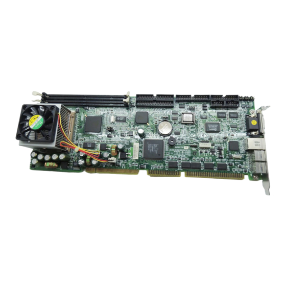
Page 14: Pcb Layout Drawing
PCB Layout Drawing I8280 Winbond 83627HF Intel i82810 IT8888HF Mechanical Drawing 6 • Introduction... -
Page 15: Chapter 2 Installation
Installation This chapter provides information on how to use the jumpers and connectors on the NuPRO-770 in order to set up a workable system. The topics covered are: CPU Installation Memory Installation Jumpers Setting Connectors Pin Assignments Watchdog timer configuration CPU Installation The NuPRO-770 industrial computer Main board supports a Socket-370 processor socket for Intel Celeron, Pentium III FC-PGA processors. -
Page 16: Memory Installation
Memory Installation The NuPRO-770 industrial computer main board supports one 168-pin DIMM socket for a maximum total memory of 512 MB. The memory modules can come in sizes of 32MB, 64MB, 128MB, and 256MB SDRAM. Jumpers on the NuPRO-770 The jumpers on the NuPRO-770 allow you to configure your main board according to the needs of your applications. - Page 17 ♦ JP1, JP2 and JP3: set COM2 as RS-232/422/485 Interface 4 5 6 4 5 6 2 4 6 RS-232 1 3 5 1 2 3 1 2 3 RS-422 RS-485 The default status sets COM2 as RS-232 port. ♦ JP4 and JP5: CPU & SDRAM Frequency Setting Jumper Setting SDRAM Frequency...
-
Page 18: Connectors Pin Assignments
Connectors Pin Assignments The connectors on the NuPRO-770 allow you to connect external devices such as keyboard, floppy disk drives, hard disk drives, printers, etc. The following tables list the connectors on NuPRO-770 and their respective functions. ♦ CN1, CN4: EIDE Connectors (CN1: primary) ♦... - Page 19 ♦ CN1, CN4: EIDE Connectors CN1: Primary IDE Connector, CN4: Secondary IDE Connector Signal Name Pin # Pin # Signal Name Reset IDE Ground Host data 7 Host data 8 Host data 6 Host data 9 Host data 5 Host data 10 Host data 4 Host data 11 Host data 3...
- Page 20 ♦ CN3: Parallel Port Connector Signal Name Pin # Pin # Signal Name Line printer strobe AutoFeed PD0, parallel data 0 Error PD1, parallel data 1 Initialize PD2, parallel data 2 Select PD3, parallel data 3 Ground PD4, parallel data 4 Ground PD5, parallel data 5 Ground...
- Page 21 ♦ CN8: VGA CRT Connector Signal Name Pin # Pin# Signal Name Green Blue N.C. N.C. N.C. N.C. HSYNC VSYNC ♦ CN10: System temperature detection This connector is used to connect a cable to thermal sensor Pin # Signal Name Virtual GND Thermistor ♦...
- Page 22 ♦ CN15: General Purpose System Signals Power Speaker Reset Switch Power ATX Power Lock Interface Pin # ATX Power Interface Signals PS_ON 5V SB (standby +5V) • Power LED and Keylock: Pins 1 - 5 The power LED indicates the status of the main power switch. The Keylock# signal is used to disable the keyboard function when it is short to GND.
- Page 23 ♦ CN16: PS/2 Mouse Connector Pin # Signal Name Mouse data N.C. N.C. Mouse Clock N.C. ♦ CN17: PS/2 Keyboard Connector Pin # Signal Name Keyboard data N.C. Keyboard clock N.C. ♦ FN1: CPU fan connector FN1 is a 3-pin header for the CPU fan. The fan must be a 12V fan. Pin # Signal Name Fan speed...
-
Page 24: Chapter 3 Bios Configuration
BIOS Configuration On the NuPRO-770 BIOS, we provide the following key features: PCI plug and play support DMI BIOS Support: Desktop Management Interface (DMI) allows users to download system hardware-level information such as CPU type, CPU speed, internal/external frequencies and memory size. -
Page 25: Chapter 4 Intel 810 Chipset Hardware And Vga Driver
Intel 810 Chipset Hardware and VGA Driver This chapter describes the installation procedure of Intel 810 chipset Device Driver for Windows 95/98/2000. Hardware Configuration File Installation This section describes system requirements of Intel 810 chipset Device Driver. This driver has been designed for and tested with Windows 98/95. The system must contain a supported Intel processor and chipset configuration. - Page 26 Installing Hardware Configuration File This subsection describes how to install the hardware configuration file on a system where Windows 98/95 is installed. Note: Record the location of the Windows 95/98/2000 directory before installing the driver. 1. Check the System Requirements. Windows 95/98/2000 must be fully installed and running on the system prior to running this software.
-
Page 27: Vga Driver Installation
VGA Driver Installation This section provides information on how to install the VGA driver that come in the Compact Disk with the package. Please follow the instructions set forth in this section carefully. Please note that there must be relevant software installed in your system before you could proceed to install the VGA driver. - Page 28 Installing the Drivers for Windows NT 4.0 IMPORTANT: You should install the Windows NT 4.0 with at least Service Pack 4 (version number: 4.00.1381) first before installing the VGA driver. If you don't have the Windows NT 4.0 Service Pack 4, please contact your software vendor or download it from Microsoft's web site.
-
Page 29: Chapter 5 Lan Driver Installation
LAN Driver Installation This chapter describes LAN driver installation for the onboard Ethernet controller Intel 82559. The relative drivers are under the following ADLINK CD directory: X:\NuPRO\Drivers\LAN\82559, where X: is the location of the CD-ROM drive. Software and Drivers Support The 82559 drivers support the following OS or platforms: Windows 98, Windows 95, Windows 2000, Windows NT Novell Netware, DOS Setup for Novell NetWare DOS... -
Page 30: Driver Installation On Windows 2000
Driver Installation on Windows 2000 The Windows 2000 may install the LAN driver. We recommend you to manually installed the most updated LAN driver, which shipped with ADLINK CD to guarantee the compatibility. After installing the Windows 2000, please update the new drivers by the following procedures. 1. -
Page 31: Driver Installation On Windows 98
Driver Installation on Windows 98 The Windows 98 will install the LAN driver automatically. We recommend you to manually updated the LAN, which on the ADLINK CD to guarantee the compatibility. After installing Windows 98, please update the new drivers by the following procedures. -
Page 32: Driver Installation On Windows Nt
Driver Installation on Windows NT Before install the LAN driver on Windows NT, please copy the LAN driver in the CD to a floppy diskette. You have to put a new disk into drive A, then type the following batch command under DOS environment to copy the relative NT drivers. -
Page 33: Chapter 6 Watchdog Programming
Watchdog Programming Watchdog Timer Configuration The Watch Dog Timer (WDT) can monitor the system's status. Once you give a value to WDT, the timer will begin to count down. To re-program a new value to WDT, or move keyboard can restart the WDT. If the system is idle or hang, it will reboot when the timer timeout. -
Page 34: How To Test The Wdt
Under DOS, Windows 95 or 98 Make a project program with wdt.cpp under Turbo C/C++. Under Windows NT The library installation procedure: 1. Run the setup program under NT environment. 2. Reboot the system. You can also write your own DLL by referring the DOS source we provide. -
Page 35: Chapter 7 Hardware Doctor Utility
Hardware Doctor Utility This chapter introduces Hardware Doctor Utility that comes with the CPU board in conjunction with the onboard hardware monitoring function (embedded in Winbond’s Super I/O chip W83627HF). The sections in the following pages describe the functions of the utility. Hardware Doctor is a self-diagnostic system for PC and must be used with Winbond’s W83781D/W83782D IC series products. -
Page 36: Warranty Policy
Warranty Policy Thank you for choosing ADLINK. To understand your rights and enjoy all the after-sales services we offer, please read the following carefully. Before using ADLINK’s products please read the user manual and follow the instructions exactly. When sending in damaged products for repair, please attach an RMA application form which can be downloaded from: http://rma.adlinktech.com/policy/. - Page 37 • Damage caused by not following instructions in the User's Manual. • Damage caused by carelessness on the user's part during product transportation. • Damage caused by fire, earthquakes, floods, lightening, pollution, other acts of God, and/or incorrect usage of voltage transformers. •...
Need help?
Do you have a question about the NuPRO-770 Series and is the answer not in the manual?
Questions and answers