
Related Manuals for FS S5860-48SC


Summary of Contents for FS S5860-48SC
- Page 1 S5860-48SC Switch Hardware Installation and Maintenance Guide V1 .0 .2306A Innovation · Expertise · Agility...
- Page 2 Preface Audience : This document is for network engineers responsible for installing and maintaining S5860-48SC switch. Experience with network equipment installation and maintenance is required. Feature Statement: Please visit the FS.COM Technical Documents page to download the datasheet and obtain information on the specifications supported by the product .
-
Page 3: Table Of Contents
Contents 1. Hardware Installation and Parts Replacement 1.1 Installation Procedure 1.2 Installation Preparation 1.3 Installing a Switch 1.4 Installing Modules 1.5 Connecting a Switch 1.6 Post-Installation Checks 1.7 System Commissioning 1.8 Parts Replacement 2. Troubleshooting After Installation 2.1 Troubleshooting Flowchart 2.2 Guide to Using Switches 2.3 Guide to Using Optical Modules Innovation ·... -
Page 4: Hardware Installation And Parts Replacement
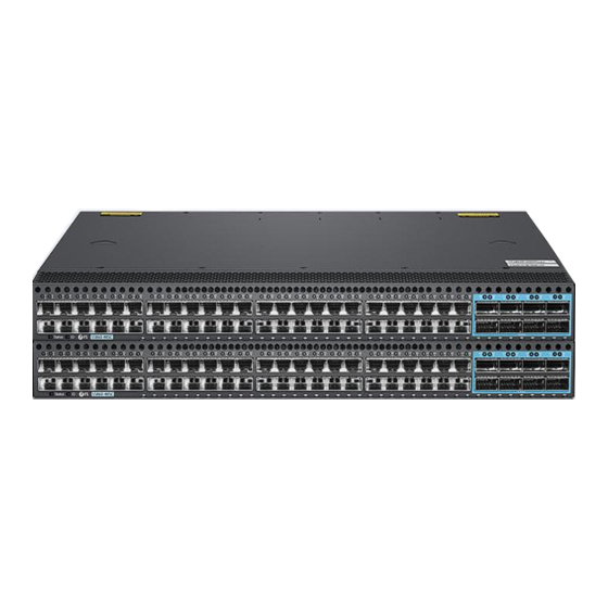
Complete QoS features differentiate services according to business needs to ensure the prompt transmission of key data.S5860-48SC switch is a 10 Gigabit device and supports 48 10G rate ports and 8 100G rate ports. -
Page 5: Installation Procedure
Post- Installation Checks 1.2 Installation Preparation S5860-48SC switch is a relatively complex device. Before installation, careful planning and arrangements should be made for the installation location, networking mode, power supply and wiring of the devices. Confirm the following before installation: •... - Page 6 Hardware Installation and Parts Replacement Switch Hardware Installation and Maintenance Guide 1.2.2 Mounting the Cabinet or Rack Precautions When mounting the cabinet, please note the following: • All expansion bolts for fastening the cabinet base to the ground should be installed and tightened in sequence from bottom to up (large flat washer, spring washer, and nut), and the installation holes on the base and the expansion bolts are aligned.
-
Page 7: Installing A Switch
1.3 Installing a Switch Precautions Before installing S5860-48SC switch in a cabinet, please check whether the racks are properly positioned. If the racks are too closeto the front door of the cabinet, you may not be able to close the front door after plugging in the Ethernet and fiber cables .The front panel of the switch should be at least 10 mm (0.39 in.) - Page 8 S5860-48SC switch can be installed in a standard 19-inch four-post EIA rack. Mount the switch in the rack with the front panelfacing forward. You are advised to use a tray to install S5860-48SC switch and secure the tray on the rack, or use the rack-mount guides to secure the switch.S5860-48SC switch has a small depth and are not equipped with rear brackets.
-
Page 9: Installing Modules
Hardware Installation and Parts Replacement Switch Hardware Installation and Maintenance Guide 1.3.2 Mounting the Switch on a Workbench In most cases, users do not have a standard 19-inch rack. Therefore, the most common method is to place the switch on. 1. - Page 10 Hardware Installation and Parts Replacement Switch Hardware Installation and Maintenance Guide Slide the fan module into the slot. Verify that the fan module is in the correct orientation. • • If you find it difficult to fully insert the fan module, pull the fan module out, and slide it into the slot again.
- Page 11 Hardware Installation and Parts Replacement Switch Hardware Installation and Maintenance Guide Slide the power module into the slot gently. Verify that the power module is in the correct orientation. • • If you find it difficult to fully insert the power module, pull the power module out, align it to the guide rails and slide it into the slot again.
- Page 12 Hardware Installation and Parts Replacement Switch Hardware Installation and Maintenance Guide 3. Check whether the retainer strip is seated securely. If you can remove the strip without pressing the retainer strip latch, it indicates that the strip is not installed properly. Try the other side of the strip. 4.
-
Page 13: Connecting A Switch
Hardware Installation and Parts Replacement Switch Hardware Installation and Maintenance Guide • Cover idle optical ports with dust plugs. All optical ports on a newly delivered switch are covered with dust plugs. • When inserting an optical module to a port, hold the optical module horizontally. If the optical module cannot be completely inserted into the optical port, do not force it into the port. - Page 14 Switch Hardware Installation and Maintenance Guide There is one ground terminal on the back of the S5860-48SC switch chassis, which should be connected to the grounding lug of the rack first, and then connect the grounding lug to the grounding bar of the equipment room.
- Page 15 Hardware Installation and Parts Replacement Switch Hardware Installation and Maintenance Guide 1.3.3 EMC Grounding 2. Lock the AC power cable with the locking strap. 3. Connect the other end of the AC power cable to the external AC power supply system. - Perform the following steps to connect the DC power cables: 1.
- Page 16 Hardware Installation and Parts Replacement Switch Hardware Installation and Maintenance Guide 1.5.4 Connecting Optical Fibers Insert the single-mode or multi-mode fiber into the corresponding interface according to the panel identification, and distinguish the transmit and receive ends of a fiber cable. 1.5.5 Connecting High-speed Cables •...
-
Page 17: Post-Installation Checks
Hardware Installation and Parts Replacement Switch Hardware Installation and Maintenance Guide To remove a high-speed cable, gently push the cable connector and then pull the handle of the connector. Do not directly pull the cable connector with force. See Figure 8. Figure 8: Removing a High-speed Cable 8. -
Page 18: System Commissioning
Hardware Installation and Parts Replacement Switch Hardware Installation and Maintenance Guide 1.6.2 Verifying Cable Connection • The UTP and STP cables match with the interface type. • Cables are properly bundled. • Grounding cables are connected properly and observe the requirement. •... - Page 19 Hardware Installation and Parts Replacement Switch Hardware Installation and Maintenance Guide Step 1: Connecting the Ethernet Cable 1. Plug the DB-9 connector of the Ethernet cable into the serial port of the PC. 2. Connect RJ45 connector of the Ethernet cable to the console port of the switch. Step 2: Check the Serial Port Number Open Device Manager on the computer and check the serial port number.
- Page 20 Hardware Installation and Parts Replacement Switch Hardware Installation and Maintenance Guide Step 4: Setting Terminal Parameters Parameter requirements: Baud rate is 9600, connection type is Serial, fill in COM port number according to the actual situation. The specific diagram is as follows. Figure 10: Setting Terminal Parameters Step 5: Once the serial port parameters are set, click <Open>...
-
Page 21: Parts Replacement
Hardware Installation and Parts Replacement Switch Hardware Installation and Maintenance Guide 1.8 Parts Replacement 1.8.1 Removing a Power Module and Fan Module Removing a Fan Module 1. Loosen the captive screws of the fan module. 2. Grasp the handle and pull the fan module out of the slot gently. 3. - Page 22 Hardware Installation and Parts Replacement Switch Hardware Installation and Maintenance Guide Pull PSM-C150WAC power module out of the slot gently. • • Install the filler panel in the empty slot to allow for adequate airflow and keep out dust. 1.8.2 Replacing an Optical Module When replacing the optical module, pay attention to the following requirements: •...
- Page 23 Hardware Installation and Parts Replacement Switch Hardware Installation and Maintenance Guide 2. Before replacing an optical module, determine in which cabinet and chassis the optical module is installed, find the optical module in the chassis, and attach a label to the optical module.Record optical fiber locations on the optical module to be replaced and check whether the labels on the optical fibers are correct and clear.
- Page 24 Hardware Installation and Parts Replacement Switch Hardware Installation and Maintenance Guide There are two types of buckles on the optical module. A pull-rod handle that needs to be turned over to open, as shown in Figure 3. The other is a handle-type handle, which is automatically opened during the process of pulling the handle, as shown in Figure 15.
- Page 25 Hardware Installation and Parts Replacement Switch Hardware Installation and Maintenance Guide Procedures 1. Before replacing the faulty switch, be sure to clearly mark the corresponding relationship between the network cable and the port. 2. Check whether the business is ready for power-off, and save relevant business information. 3.
-
Page 26: Troubleshooting After Installation
Troubleshooting After Installation Innovation · Expertise · Agility... -
Page 27: Troubleshooting Flowchart
Troubleshooting After Installation Switch Hardware Installation and Maintenance Guide 2.1 Troubleshooting Flowchart Innovation · Expertise · Agility... -
Page 28: Guide To Using Switches
Fault Symptom The login password is forgotten. Handling Method Contact FS technical support. Fault 2: The AC power module does not work Fault Symptom All LEDs on the front panel are off. The fan status LED is off, and the fan does not rotate. The power supply status LED is off. - Page 29 Sometimes glitches can appear on these hardware. 5. Contact Vendor Support: If there is still no output on the serial port, please contact FS technical support. Fault 5: The serial port console output is garbled Fault Symptom The serial port console output is garbled.
-
Page 30: Guide To Using Optical Modules
Troubleshooting After Installation Switch Hardware Installation and Maintenance Guide 2. Check whether wavelengths of optical transceivers on both sides are consistent. For example, an optical transceiver with a wavelength of 1310 nm cannot be connected to an optical transceiver of 1550 nm. 3. - Page 31 Troubleshooting After Installation Switch Hardware Installation and Maintenance Guide Figure 17: State of the release handle 1.3.3 EMC Grounding Close the release handle Open the release handle 2.3.3 Measures to Prevent Receptacle Contamination 1. Cleaning tissues must be prepared on site. You need to clean the optical connector before inserting it in the receptacle.
- Page 32 Troubleshooting After Installation Switch Hardware Installation and Maintenance Guide Figure 19: Installing a protective cap If no protective cap is available, use fibers to protect the optical module, as shown in Figure20. Figure 20: Using fibers to protect an optical module 3.
- Page 33 Troubleshooting After Installation Switch Hardware Installation and Maintenance Guide Figure 22: Cleaning a receptacle with a cotton swab When cleaning a receptacle, insert the cotton swab and turn it slowly in the receptacle. Do not use • too much strength because the receptacle may be damaged. 5.
- Page 34 FS has invested resources in product R&D, quality control, intelligent manufacturing, industry-leading experts, professional technical support, and networking solutions. All is to provide customers with higher-performance, lower-power consumption, and the most cost- effective products, promoting clients' network upgrades. For more information and technical support, welcome to contact us at www.fs.com/contact_us...
Need help?
Do you have a question about the S5860-48SC and is the answer not in the manual?
Questions and answers