Advertisement
Quick Links
Installation, Operation, and Maintenance
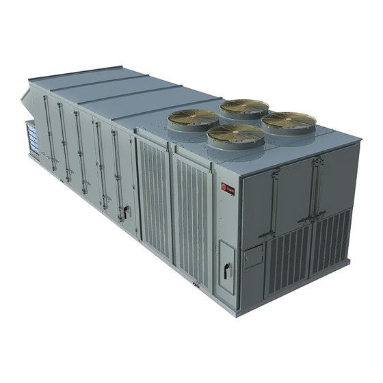
IntelliPak™ 3 with Symbio™ 800
Commercial Rooftop Air Conditioners
"A" and later design sequence
RA *20, *25, *30, *40, *50, *55, *60, *70,
*75
Only qualified personnel should install and service the equipment. The installation, starting up, and servicing of heating, ventilating, and air-conditioning equipment
can be hazardous and requires specific knowledge and training. Improperly installed, adjusted or altered equipment by an unqualified person could result in death or
serious injury. When working on the equipment, observe all precautions in the literature and on the tags, stickers, and labels that are attached to the equipment.
October 2024
SAFETY WARNING
RT-SVX080A-EN
Advertisement

Subscribe to Our Youtube Channel
Related Manuals for Trane IntelliPak 3 with Symbio 800


Summary of Contents for Trane IntelliPak 3 with Symbio 800
- Page 1 Installation, Operation, and Maintenance IntelliPak™ 3 with Symbio™ 800 Commercial Rooftop Air Conditioners “A” and later design sequence RA *20, *25, *30, *40, *50, *55, *60, *70, SAFETY WARNING Only qualified personnel should install and service the equipment. The installation, starting up, and servicing of heating, ventilating, and air-conditioning equipment can be hazardous and requires specific knowledge and training.
-
Page 2: Warnings, Cautions, And Notices
(HCFCs). Not all refrigerants containing these compounds bump cap, fall protection, electrical PPE and arc have the same potential impact to the environment. Trane flash clothing). ALWAYS refer to appropriate advocates the responsible handling of all refrigerants. - Page 3 Follow EHS Policies! This document and the information in it are the property of Trane, and may not be used or reproduced in whole or in Failure to follow instructions below could result in part without written permission. Trane reserves the right to death or serious injury.
-
Page 4: Table Of Contents
Table of Contents Model Number Description ....8 Unit Rigging and Placement....33 General Installation Requirements . - Page 5 Demand Control Ventilation (DCV) ..77 Trane Start-up Checklist ....68 Relief Fan and Space Static Pressure Critical Control Parameters and Dry Control .
- Page 6 Table of Contents Low Compressor Suction Pressure Electric Heat - Modulating ....91 Protection......84 Electric Heat Protection .
- Page 7 Table of Contents Relief Fan Curves ..... . . 114 Variable Speed Manifolded with Fixed Speed Compressors ......151 Component Static Pressure Drops .
-
Page 8: Model Number Description
Model Number Description Digit 1 — Unit Type Digit 10, 11— Design Sequence Digit 19 — Relief Fan Motor R = Packaged Rooftop AA = Current Design Sequence 0 = None 2 = 6 hp 3 = 8 hp Digit 2 — Unit Function Digit 12 —... - Page 9 Model Number Description Digit 27 — Outside Air Digit 41 — Modulating Hot Gas Reheat and Digit 48 — Controls Expansion Hardware Hot Gas Bypass 0 = None 0 = None 0 = None 1 = 0-25% Manual Damper A = Expansion Module 1 = Hot Gas Reheat 2 = 0-100% Economizer 3 = Hot Gas Bypass...
-
Page 10: General Information
An optional roof curb, number, electrical characteristics, refrigerant charge, unit specifically designed for the units is available from Trane. wiring diagram numbers, as well as other pertinent unit The roof curb kit must be field assembled and installed data. -
Page 11: Pre-Installation
Trane, to VALIDATE this WARRANTY. Contractor • Take photos of the damage, if possible. must provide a two-week startup notification and true start date to Trane (or an agent of Trane specifically authorized • The owner must provide reasonable evidence that the to perform startup). -
Page 12: Additional Requirements For Units Requiring Disassembly
When a new fully assembled IntelliPak is shipped and • Start-up must be performed by Trane or an agent of received from our Trane manufacturing location, and, for Trane specifically authorized to perform start-up and any reason, it requires disassembly or partial disassembly, warranty of Trane®... -
Page 13: Dimensional Data
Dimensional Data Table 1. Unit Dimensions Refrigeration Pre-Evaporator Coil Overall Footprint Relief Option System Unit Function Outside Air Filter Length Length H (in.) W (in.) Tons Performance Digit Digit Digit (in.) (in.) Type Type Type Type Digit 27 Type Digit 24 Panel A,B,C,D,F,G 220.90... - Page 14 Dimensional Data Table 1. Unit Dimensions (continued) Refrigeration Pre-Evaporator Coil Overall Footprint Relief Option System Unit Function Outside Air Filter Length Length H (in.) W (in.) Tons Performance Digit Digit Digit (in.) (in.) Type Type Type Type Digit 27 Type Digit 24 A,B,C,D,F,G Panel...
- Page 15 Dimensional Data Figure 1. 20 to 30 ton — front view (inches) 90.63 40.28 27.31 FRONT VIEW 20-30T RT-SVX080A-EN...
- Page 16 Dimensional Data Figure 2. 20 to 30 ton — left view of sample configuration (inches) 220.88 38.85 87.66 81.59 69.33 40.61 213.00 LEFT SIDE VIEW 20-30T / NO HEAT / RELIEF FANS / PANEL FILTERS RT-SVX080A-EN...
- Page 17 Dimensional Data Figure 3. 40 to 55 ton — front view (inches) 90.63 40.28 27.31 FRONT VIEW 40-55T RT-SVX080A-EN...
- Page 18 Dimensional Data Figure 4. 40 to 55 ton — left view of sample configuration (inches) 81.59 87.66 79.33 300.88 LEFT SIDE VIEW 40-55T / ELECT. HT. / CART. FILTERS Figure 5. 60 to 75 ton — front view (inches) 116.13 40.38 27.32 FRONT VIEW...
-
Page 19: Roof Curb
Dimensional Data Figure 6. 60 to 75 ton — left view of sample configuration (inches) 320.73 38.63 81.59 87.90 79.71 41.27 23.29 4.52 281.88 LEFT SIDE VIEW 60-75T / GAS HEAT / BAROMETRIC RELIEF / PANEL FILTERS Roof Curb Figure 7. Service clearance 96"... - Page 20 Dimensional Data Figure 8. Roof curb dimensions (inches) RETURN OPENING 4.01 OPENING TOP OF CURB 18.00 1.33 SUPPLY OPENING OPENING 4.01 BOTTOM OF CURB 7.50 16.60 7.00 RT-SVX080A-EN...
- Page 21 Dimensional Data RT-SVX080A-EN...
- Page 22 Dimensional Data RT-SVX080A-EN...
- Page 23 Dimensional Data Figure 9. Base and pedestal 5.5" 3.4" GASKET BASE 4.3" 1.5" .5" 2 X 4 NAILER ROOF CURB TYPICAL ROOF CURB & BASE DETAIL SECT. A-A PLAN VIEW 5.5" 2.5" 3.4" LIFTING LUG 7.5" BASE BASE 4.3" 2.8" PEDESTAL 1.5"...
-
Page 24: Electrical Entry Details
Dimensional Data Electrical Entry Details Figure 10. Electrical connections (inches) ISO VIEW C CAB ISO VIEW A & B CAB POWER BOX CONTROL BOX DOOR 6.48 3.54 OR 4.55 8.06 CONTROL BOX SIDE PANEL 8.22 REAR ISO VIEW TOP VIEW ELECTRIC MAIN POWER ENTRY ELECTRIC MAIN POWER ENTRY RT-SVX080A-EN... -
Page 25: Access Clearances
Dimensional Data Access Clearances Figure 11. Minimum access clearances – 20 to 30 ton 32" SUPPLY FAN 26.5" SUPPLY FAN 20.5" OUTSIDE AIR SUPPLY FAN ELECTRIC HEAT POWER CONTROL BOX CONTROL BOX CONTROL BOX PLAN VIEW 20-30T DOOR LAYOUT Figure 12. Minimum access clearances – 40 to 55 ton 32"... - Page 26 Dimensional Data Figure 13. Minimum access clearances – 60 to 75 ton 32" SUPPLY FAN 26.5" SUPPLY FAN 20.5" OUTSIDE AIR SUPPLY FAN POWER CONTROL BOX CONTROL BOX PLAN VIEW 60-75T DOOR LAYOUT RT-SVX080A-EN...
-
Page 27: A2L Information
• To be repaired only by trained service At all times, Trane’s maintenance and service guidelines shall be followed. If in doubt, contact Trane technical personnel. support for assistance. • Do not puncture refrigerant tubing. -
Page 28: Leak Detection
Verify continuity of earth bonding. The recovery equipment shall be in good working order • Replace electrical components with Trane replacement with instructions available. Equipment shall be suitable for parts, or those meeting the same ratings and qualified the recovery of the flammable refrigerant. For specific for flame arrest protection, UL LZGH2 category. -
Page 29: Decommissioning
A2L Information • Ensure that the refrigerating system is earthed prior to the equipment are removed from site promptly and all charging the system with refrigerant. isolation valves on the equipment are closed off. • Label the system when charging is complete (if not 11. -
Page 30: Minimum Room Area Limits
A2L Information Minimum Room Area Limits Table 3. Minimum room area (continued) (Refrigerant charge greater than 3.91 lb Minimum Room Area per circuit) Tonnage Equipment with R–454B charge amounts greater than 3.91 1301 lb per circuit may require additional circulation or ventilation airflow mitigation strategies. -
Page 31: Leak Detection System
A2L Information Minimum Room Area (A ) Adjustments rooftop systems include non-standard solutions that might be considered for these applications. Use equation below to adjust the minimum room area, as Applications which should be investigated before using the applicable, based on the unit’s installation height, altitude, standard modulating hot gas reheat option include: and occupancy level it serves. - Page 32 A2L Information • Provide an output to energize additional mechanical actions. Mitigation actions may be verified by disconnecting ventilation (if needed). the sensor. • Units without airflow proving will disable electric heat The refrigerant sensors do not need service. Use only sources.
-
Page 33: Installation
Step-by-step curb assembly and installation instructions Figure 14. Typical unit base and roof curb cross ship with each Trane accessory roof curb kit. Follow the section instructions carefully to assure proper fit-up when the unit is set into place. - Page 34 Installation Figure 15. Lug locations Tonnage Cartridge Filter Efficiency RA/RX Cabinet 20, 25, 30 40,50,55 High/Eflex High/Eflex 70,75 High/Eflex High/Eflex RT-SVX080A-EN...
-
Page 35: General Installation Requirements
Installation General Installation ☐ All field-installed wiring must comply with NEC and applicable local codes. Requirements Field Installed Control Wiring The checklist below is a summary of the steps required to successfully install a Commercial rooftop unit. This ☐ Complete the field wiring connections for the variable checklist is intended to acquaint the installing personnel air volume controls as applicable. -
Page 36: Voltage Supply
Installation ☐ (Units with StatiTrac) Field supplied pneumatic tubing connected to the proper fitting in the main control box, and the other end routed to a suitable sensing location within the controlled space. The 2.2% imbalance in this example exceeds the Voltage Supply maximum allowable imbalance of 2.0%. - Page 37 Installation heating mode as follows. (Keep in mind when determining Dual Source Power units (200–230V with Electric Heat) LOADS that the compressors and condenser fan motors These units will have two circuit values shown on the don't run while the unit is in heating mode). nameplate.
- Page 38 Installation Table 5. Compressor electrical service sizing data (20 to 75 tons) (continued) 200 V 230 V 460 V 575 V No. of Tons Compressors RLA (ea.) LRA (ea.) RLA (ea.) LRA (ea.) RLA (ea.) LRA (ea.) RLA (ea.) LRA (ea.) 40.3 40.3 19.2...
- Page 39 Installation Table 6. Condenser fan electrical service sizing data (20-75 ton) (continued) No. of 200 V 230 V 460 V 575 V Tonnage FLA (ea.) FLA (ea.) FLA (ea.) FLA (ea.) Motors 75 Std 75 Low Ambient Variable Speed Fan Table 7.
- Page 40 Installation Table 9. Electrical service sizing data — Relief fan motors — 20 to 75 tons 200 V 230 V 460 V 575 V Tonnage HP (Total) No. of Motors FLA (ea.) FLA (ea.) FLA (ea.) FLA (ea.) 12.8 12.8 19.5 19.5 12.8...
-
Page 41: Main Unit Power Wiring
Installation Main Unit Power Wiring WARNING Electrical Shock Hazard! Table 12, p. 42 lists the field connection wire ranges for both the main power terminal block 2XD1 and the optional Failure to follow instructions below could result in main power disconnect switch 2QB1. Service Sizing Data death or serious injury. - Page 42 Installation Figure 16. Typical field power wiring (20 to 75 ton) RE 200/230 ONLY: ADDITIONAL FIELD SUPPLIED DISCONNECT SWITCH FIELD SUPPLIED DISCONNECT SWITCH PITCH PITCH POCKET POCKET 3-WIRE POWER SUPPLY PLUS GROUND 3-WIRE POWER SUPPLY PLUS GROUND Table 12. Customer connection wire range Units with Main Power Terminal Block (All Voltages) Units with Main Power Disconnect Switch (All Voltages) Block Size...
-
Page 43: Supply Fans
Installation Supply Fans removed, shown in Figure 17, p. 43. Gently spin each fan to verify there is no wheel-to-cone interference. If Remove Shipping Tie Down adjustment is required, loosen fan shaft set screw and reposition fan to get correct wheel/cone overlap. Remove supply fan shipping tie down hardware. -
Page 44: O/A Sensor And Tubing Installation
Installation Figure 19. Supply fan cone overlap On VAV systems, a duct pressure transducer and the outside air sensor is used to control the discharge duct static pressure to within a customer-specified range. On CV and VAV units equipped with modulating relief with Statitrac, a space pressure transducer and the outside air sensor is used to control the relief fan and dampers to relieve static pressure to within a customer-specified range,... -
Page 45: Units With Statitrac
Installation Figure 21. Return air pressure tubing schematic Figure 22. Pressure sensing tube location Fresh Air Transducer Left side Outside Air Return Plenum Pressure Units with Statitrac Space Pressure 1. Open the control panel, and locate the Space Pressure Tube Fitting tubing connector. -
Page 46: Refrigeration System
Installation Figure 23. Pressure sensing Figure 24. Condensate trap installation Top Port Connection 2' x 3/16" OD Tubing Factory Provided Post Outside Air Pneumatic Tubing Pressure (Field Installed) Sensor 1.25” NPT Connection Sensor Mounting Bracket Attached to Roof Field Supplied Condensate Piping 4.5”... -
Page 47: Compressor Crankcase Heaters
Installation Figure 26. Condensate drain locations for units with Note: For conversion from Natural Gas to Propane refer to staggered indoor coils the LP Converstion Kit (RT-SVN033*-EN) for part numbers and installation instructions. WARNING Hazardous Gases and Flammable Vapors! Failure to observe the following instructions could result in exposure to hazardous gases, fuel substances, or substances from incomplete combustion, which could result in death or serious... -
Page 48: Explosion Hazard
Installation Following the guidelines listed below will enhance both the Failure to use a pressure regulating device will result in installation and operation of the furnace. incorrect gas pressure, which can cause erratic operation due to gas pressure fluctuations as well as Note: In the absence of local codes, the installation must damage the gas valve. -
Page 49: Connecting The Gas Supply Line To The Furnace Gas Train
Installation Figure 28. Gas heat component dimensions Flue Vent Heat access (850 MBH shown) Gas pipe Combustion entry with inlet rain shield grommet CPVC Drain (40-75 ton only) Note: See gas piping figures for NPT size Tonnage Heater Size 250, 350 & 500 20–30 6.75 7.59... - Page 50 Installation Table 15. Sizing natural gas pipe mains and branches Gas Input (Cubic Feet/Hour) Gas SupplyPipe Run (ft) 1¼" Pipe 1½" Pipe 2" Pipe 2½" Pipe 3" Pipe 4" Pipe 1,060 1,580 3,050 4,860 8,580 17,500 1,090 2,090 3,340 5,900 12,000 1,680 2,680...
- Page 51 Installation Table 18. Propane (LP) – high altitude rating reduction orifice chart Heater size 0-2000' 3000' 4000' 5000' 6000' 7000' 8000' 9000' 10000' (MBh) 1.75 mm 1.65 mm 1200 1.9 mm Note: Orifice sizes required to reduce input ratings by 4% per every 1000’ above 2000’ per the National Fuel Gas Code Z223.1. 850,000 Btu/Hr at Sea Level input is 737,000 Btu/Hr RT-SVX080A-EN...
- Page 52 Installation Figure 29. Unit gas trains 250/350 MBh two stage/ Figure 30. Unit gas trains 250/350 MBh ultra modulating modulating and 500 MBh two stage/modulating Modulating valve (not on 2-stage) Modulating valve (not on 2-stage) One stage valve on Modulating, two stage One stage valve on 2-stage valves...
-
Page 53: Flue Assembly And Rain Shield
Installation Figure 31. Unit gas trains 500 MBh ultra modulating Figure 32. Unit gas trains 850/1200 MBh four-stage/ modulating/ultra modulating Modulating valve One stage valve UL 536 Flexible Modulating valve Metallic Hose (not on 4-stage) One stage valves One stage valve UL 536 Flexible Metallic Hose One stage valve... -
Page 54: Electric Heat Units
Installation gas heat section. It is extremely important that the on the dampers so that they are fully closed at 0% condensate be piped to a proper drain. Refer to the command. appropriate illustration in Figure 28, p. 49 for the location of 5. - Page 55 Installation that provides the supply power to the unit terminal block listed in Table 20, p. 57 Table 21, p. 58 for outside or the unit mounted disconnect switch. air damper position 1, then determine the appropriate pressure increase needed. Identify the correct return 3.
- Page 56 Installation Figure 33. Outside air damper OUTSIDE AIR DAMPERS RETURN AIR DAMPERS BOTTOM VIEW OUTSIDE AIR DAMPERS BOTTOM VIEW RETURN AIR DAMPERS RT-SVX080A-EN...
- Page 57 Installation Table 19. Outside air damper travel adjustment Outside Air Damper Crank Arm Hole Return Air Damper Crank Configuration Arm Hole Configuration Position 1 - 3 90° 9 - 11 90° 1 - 4 75° 9 - 12 75° 1 - 6 60°...
- Page 58 Installation Table 21. Outside air damper pressure drop — Traq™ Traq™ Outside Air Damper Position 20, 25 and 30 Ton 4000 0.07 0.08 0.09 0.17 0.26 0.89 6000 0.15 0.18 0.21 0.40 0.64 2.82 7000 0.20 0.26 0.31 0.56 0.90 8000 0.26 0.35...
- Page 59 Installation Table 22. Return air pressure increase (continued) Return Air Damper Position 14000 0.00 0.11 0.25 0.43 16000 0.00 0.13 0.28 0.55 18000 0.00 0.14 0.31 0.67 20000 0.00 0.15 0.33 0.81 22000 0.00 0.16 0.35 0.96 24000 0.00 0.17 0.37 1.13 Units with Dual Actuators (60, 70 and 75 Ton)
- Page 60 Installation Table 23. Outside Air Pressure Drop (inches w.c.) – No Traq™ (continued) No Traq™ Outside Air Damper Position 100% 22000 0.35 0.72 1.11 1.58 24000 0.40 0.85 1.33 1.90 26000 0.47 0.99 1.57 2.24 28000 0.53 1.14 1.83 2.61 30000 0.60 1.31...
- Page 61 Installation Figure 34. Actuator stroke limit adjustment Figure 35. Actuator auto-scaling feature details Angle of Rotation Limiter Scale Shows % of Full Stroke Control Reversing Switch Must Be Set to Match Spring Return Direction RT-SVX080A-EN...
-
Page 62: Startup The Unit
Startup the Unit Electrical Phasing Use the following in conjunction with the “Trane Start-up Checklist,” p. 68, to ensure that the unit is properly installed WARNING and ready for operation. Be sure to complete all of the procedures described in this section before starting the unit Hazardous Voltage! for the first time. - Page 63 Startup the Unit WARNING Rotating Components! Failure to disconnect power before servicing could result in rotating components cutting and slashing technician which could result in death or serious injury. During installation, testing, servicing and troubleshooting of this product it may be necessary to work with live and exposed rotating components.
-
Page 64: Direct-Drive Supply Fan Speed Adjustment
Startup the Unit Direct-Drive Supply Fan Speed Table 26. RPM and Hz ranges for DDP supply fan speed adjustments (continued) Adjustment Fan Speed (RPM) VFD Frequency Range (Hz) Units equipped with a DDP Supply Fan do not use belt/ sheave arrangements to adjust fan speed. This adjustment (if required) is made through the Fan VFD 1200 by setting the supply fan Min/Max frequency at each supply... -
Page 65: Gas Furnace Startup
Startup the Unit High-Fire Adjustment Table 28. K-factor for relief fans Fan Model K-factor WARNING K3G500 Hazardous Gases and Flammable K3G560 Vapors! Failure to observe the following instructions could Use this equation to determine flow for relief fans: result in exposure to hazardous gases, fuel substances, or substances from incomplete combustion, which could result in death or serious Where K is determined based on the fan model number, ρ... -
Page 66: Low-Fire Adjustment (250 And 350 Mbh Two Staged Only)
Startup the Unit Low-Fire Adjustment (250 and 350 MBH If adjustment is needed, adjust the regulator on the valve. Refer to Figure 38, p. 67 for two stage valve on Two Staged only) 250 & 350 MBh two stage, and Figure 37, p. -
Page 67: Final Unit Checkout
Startup the Unit Final Unit Checkout Figure 37. One stage valve adjustment After completing all of the checkout and start-up procedures outlined in the previous sections (i.e., operating the unit in each of its Modes through all available stages of cooling and heating), perform these final checks before leaving the unit: Adjustment... -
Page 68: Trane Start-Up Checklist
Important: This checklist is not intended as a substitution for the contractor’s installation instruction. This checklist is intended to be a guide for the Trane Important: Except where noted, it is implied that the Trane technician just prior to unit 'startup'. Many of the... -
Page 69: Critical Control Parameters And Dry Bulb Changeover Map
Startup the Unit Table 29. Startup checklist (continued) Completed? Electric heat circuits have continuity Perform electric heat start up procedure Verify heating system matches name plate Gas Heat (if applicable) Gas heat piping includes drip leg previously installed by installing contractor Gas heat flue assembly fully installed Gas heat condensate line and heat tape installed where applicable Verify heating system matches name plate... - Page 70 Startup the Unit Figure 39. Dry bulb changeover map RT-SVX080A-EN...
-
Page 71: Sequence Of Operation
Sequence of Operation NOTICE must be set to “True” to allow this function to operate. Mechanical cooling (DX) is available for Rapid Restart if the Compressor Failure! Outdoor Air Temperature is above the Low Ambient Failure to follow instruction below could result in Lockout setpoint. -
Page 72: Timed Override
Occupied Unoccupied Not Zero Bypass installed and may be wired or wireless. Field installed wired sensors are available from Trane and many other sources. Unoccupied Any State Zero Unoccupied In every case, the correct type of sensor must be used. -
Page 73: Operating Modes
Sequence of Operation Cool flow control is enabled, operating mode transitions, and capacity control enables. Cool mode is reported when the control objective is to provide cooling to maintain building comfort. Direct • Single Zone VAV (Space Temperature) expansion cooling is the primary cooling source. Cool Single Zone VAV control units will also accept a mode is also reported when Economizer cooling, Maximum Heat command via Heat Cool Mode... -
Page 74: Unit
Sequence of Operation Figure 40. Operating Modes Run Inhibit The circuit is currently being inhibited from starting (and running), but may be allowed to start if the inhibiting or diagnostic condition is cleared. For example: Start Inhibited by Low Ambient Temp is displayed when outdoor air temperature is below the Low Ambient Lockout Setpoint;... -
Page 75: Pre Cool
Sequence of Operation Setpoint Active; this provides flexibility when 100% heat Heat Cool Mode Request. The controller will not use local capacity in not desired. The supply fan operates at max inputs and assume outdoor air is suitable for economizing. speed on Constant Volume Units. -
Page 76: Supply Fan Proving Operation And Method
Sequence of Operation The supply fan speed requested and commanded value • Enabling and disabling Supply Fan VFD Bypass Mode will remain at 0% any time the Active Supply Fan Run can only take place from the unit user interface. Command = OFF. -
Page 77: Operation During Manual Override And Vom (Emergency Override)
Sequence of Operation Note: The enabling and disabling of VFD Bypass will be The provided air flow measurement capabilities include dis-allowed until the Duct Static Pressure indicates periodic, automatic calibration; however, air flow gain and no flow per the below option. offset settings are provided for field adjustment. -
Page 78: Relief Fan And Space Static Pressure
Sequence of Operation Table 33. Outdoor air damper minimum ventilation control Traq Outdoor Air Flow Demand Control Description Outdoor Air Damper Compensation Ventilation Controlling Setpoints Enabled/Active Disabled Disabled Damper controls to outdoor Setpoint: air minimum flow setpoint Outdoor Air Minimum Flow Setpoint Active Outdoor Air Minimum Flow Setpoint Status... -
Page 79: Space Static Pressure Control With
Sequence of Operation Multi Zone-VAV and Constant when the unit is economizing and bringing in large quantities of outside air. Volume - Discharge Temperature Space Static Pressure Control with Units Statitrac™ These unit types provide Discharge Air Temperature Statitrac™ is an option. Space static pressure control Control in all heat, cool, and occupancy modes of operation will become active when the supply fan is On and operation. -
Page 80: Discharge Air Reset
Sequence of Operation Discharge Air Reset temperature setpoint. For Example: As space temperature cooling load increases, space temperature control will Discharge Air Reset is a method to save energy by calculate a lower Discharge Air Temperature setpoint and resetting the discharge air temperature as heating and therefore will increase cooling capacity. -
Page 81: Space Temperature Control Units
Sequence of Operation Space Temperature Control operation in Occupied Heat and Occupied Cool modes of operation; however, the Discharge Air Control method is Units used for all other modes. The table below summarizes each mode of operation and the control method applied. Single Zone VAV and Constant Volume Space Temperature See Operating Modes section for more details units use the Space Temperature Control sequence of... -
Page 82: Temperature Control
Sequence of Operation General Compressor Staging the heat type installed. The minimum fan speed can be 100%. See Heat Types for more information. Compressor staging will occur based on the unit’s As the Discharge Air Temperature Setpoint increases, the algorithms cooling capacity request and the specific heat capacity increases stages and/or modulates. -
Page 83: Alternate Staging Sequence
Sequence of Operation Compressor Staging with Variable Speed Compressor Inhibits Compressors Inhibits of compressors are typically recoverable without requiring user interaction. The inhibit of a compressor will Units with Variable Speed Compressors will always attempt be immediate once the request is issued. Inhibits originate to start the variable speed compressor first. -
Page 84: Compressor Protections
Sequence of Operation compressor running per circuit the compressor with a than the normal threshold value. These values are higher wear calculation will be chosen to stop. dependent on unit model. Ties The Low Compressor Suction Pressure Start Inhibit and Low Compressor Suction Pressure Limit work together to If multiple compressors with equal wear are available for reduce the likelihood of Low Compressor Suction Pressure... -
Page 85: Compressor Discharge Saturated
Sequence of Operation If the discharge pressure limit is preventing loading, holding delayed shutdowns are possible. Shutdowns may be or forcing unloading, an indication will be made to the user temporary or require a manual reset. interface. Loss of Charge Detection Note: The discharge pressure limit function assumes that all available condenser fans are running and limiting This function detects excessive refrigerant leakage. -
Page 86: Head Pressure Control
Sequence of Operation As frost builds on a coil, thermal resistance increases and Figure 42. Piping diagram with hot gas bypass airflow decreases. Frost buildup on the coil can also cause instabilities in superheat control. If suction saturated temperature drops below a threshold, Frost Protection will inhibit capacity in an attempt to melt the frost and allow the unit to run more efficiently. -
Page 87: Exv Control
Sequence of Operation EXV Control (Electronic control mode is to maintain suction pressure or differential pressure within the compressor operating map. Expansion Valve) In situations where the superheat rapidly falls to very low Electronic expansion valves (EXVs) control suction values, special control modes are necessary to dry out superheat to ensure the complete and efficient evaporation excess refrigerant liquid in the evaporator, suction line, and of refrigerant in the evaporator. -
Page 88: Operating Modes
Sequence of Operation Table 35. EXV Control States (continued) Control State Description Running – Pre-Position Hold Time After a compressor on the circuit starts, but before automatic control begins. Running – Suction Superheat Control Normal automatic superheat control Running – Suction Pressure Control Controlling suction pressure instead of suction superheat, to maintain adequate compressor pressure ratio or to limit high suction saturated temperature. -
Page 89: Outdoor Air Damper Fault Detection And Diagnostics (Fdd)
Sequence of Operation Outdoor Air Damper Fault Mode Status is not Cool, or a sensor required for dehumidification control is invalid. Detection and Diagnostics (FDD) Dew Point The outdoor air damper fault will have two fault detection components, faults that are generated when operating in If space dew point is greater than the space dew point minimum ventilation mode and another set when the setpoint (default = 60F) and outdoor air dew point is greater... -
Page 90: Heat Types
Sequence of Operation Economizer cooling disables and the sub-mode Cool – Unoccupied Dehumidification Offset or Space Dehumidification is reported on the user interface Temperature falls below a fixed 60°F threshold Operating Modes screen. • Or, Space Dew Point is less than Space Dew Point When Dehumidification is active, cooling capacity is Unoccupied Setpoint minus Space Dew Point offset. -
Page 91: Electric Heat - Staged
Sequence of Operation second post-purge period. Additional ignition trials follow and draft inducer pressure are determined based on the specified sequence. If 3 attempts for ignition have the heat demand received by the control via a Modbus occurred without flame detection, the control will lock out. signal. -
Page 92: Electric Heat Protection
Sequence of Operation Electric Heat Protection Heating Setpoint. The supply fan operates according to heat type installed, see Heat Types for more information. There are three automatic high temperature limit switches Heating continues until space temperature is 4°F greater that will trip when exposed to a high temperature. They will than the Unoccupied Heating Setpoint, the unit will then reset automatically once the temperature drops into an cycle off. -
Page 93: External Relief Fan Control
Sequence of Operation Table 39. Supply fan speed setpoint summary Table 41. Exhaust fan speed setpoint summary Exhaust Fan Exhaust Fan Supply Fan Speed Supply Fan Speed Supply fan Exhaust fan Setpoint Enable Setpoint operation Speed Setpoint Speed Setpoint operation Enable Disable Fan under Symbio... -
Page 94: Local Stop
Sequence of Operation Manual Control 6. Emergency Override 7. Operating Mode Off Manual control is intended for servicing the machine. It provides manual control of all of all valves, dampers, 8. Normal operating modes actuators, fans, compressors and heating functions. This If local stop, emergency stop, or equipment stop request a can be done while fans, compressors and heating systems Stop, the unit will shut down and not resume operation until... -
Page 95: Emergency Override
Sequence of Operation • Equipment Stop If one or more of the 5 VOM inputs are closed, the unit will enter the VOM mode with the highest priority (A highest, E • Emergency Stop lowest). Should the unit be in an active VOM mode and a •... -
Page 96: Heat/Cool Capacity Lockouts And Limits
If both points are True (locked out) at the same time, both These capabilities interact. Capacity Lockouts have highest will be honored. Trane Graphical Programming (TGP2) can priority. When Heat Lockout Command and Cool Lockout be used to control these points. -
Page 97: Condensate Overflow
Sequence of Operation equipment. The 0-100% value limits the amount of heating hour timer is started at this point. If the condensate capacity. overflow input returns to normal, the unit is allowed to restart. If a second condensate high level is detected Demand Limit during the 72 hour timer, the unit will shutdown but restart if Demand Limit is a function with building automation... -
Page 98: Refrigerant (R-454B) Detection And Mitigation
Sequence of Operation Refrigerant (R–454B) Detection Heat Cool Mode Status: Off and Mitigation When the unit is in Off mode and a leak is detected or sensor fails (see the figure below), a diagnostic will trigger. Equipment with R-454B refrigerant requires a refrigerant Heat Cool Mode will transition to “Fan Only”. -
Page 99: Heat Cool Mode Status: Heat
Sequence of Operation Heat Cool Mode Status: Heat detected. If the unit has Supply Fan VFD Bypass Installed and enabled, the supply fan will go to maximum speed. If When the unit is in Heat mode and a leak is detected or the Supply Fan VFD Bypass is installed but disabled AND sensor fails (see the figure below), the same diagnostics the VFD has failed, the supply fan will not start. -
Page 100: Modbus Addresses
Sequence of Operation Figure 49. Modbus Device Addressing — Rebuild Modbus Addresses Modbus Address Tool Display Name Modbus Device RTU Address Compressor 1A Not Applicable Not Applicable Condenser Fan 1 Not Applicable Condenser Fan 2 Supply Fan 1 Not Applicable Supply Fan 2 Not Applicable Relief Fan 1... -
Page 101: Controls
Controls Constant Volume System conditions that cause excessive motor temperature. These include rapid cycling, loss of charge, abnormally high Controls suction temperatures, excessive amperage, phase loss and low voltage Constant Volume Zone Panel PTC sensors are embedded in the motor windings of each (BAYSENS108*) Scroll compressor. - Page 102 Controls Figure 50. Compressor and condenser fan locations and names Refrigeration Systems: Refrigeration Systems: 20H, 20V, 25H, 25V, 30H, 30V 20H, 30S, 30H Circuit 1 Circuit 1 Condenser Condenser Fans & Fans & Motors Motors Comp 1A Comp 1B Comp 1C Comp 1A Comp 1B (2M1)
- Page 103 Controls Table 44. Compressor staging — 25H, 30S, 30H Table 50. Compressor staging — 50V Stage Comp 1A Comp 1B Comp 1C Capaci- Comp Comp Comp Speed Speed ty Step — — — — 1500 4680 — — — 1500 5220 —...
-
Page 104: Performance Data
3. Curve can show combined operating min/max for multiple tonnages. Refer to general data for appropriate operating parameters such as motor horsepower and airflow ranges. 4. Shaded areas represent unavailable selections. Contact your local Trane® representative for more information on selections in these shaded regions. - Page 105 3. Curve can show combined operating min/max for multiple tonnages. Refer to general data for appropriate operating parameters such as motor horsepower and airflow ranges. 4. Shaded areas represent unavailable selections. Contact your local Trane® representative for more information on selections in these shaded regions.
- Page 106 3. Curve can show combined operating min/max for multiple tonnages. Refer to general data for appropriate operating parameters such as motor horsepower and airflow ranges. 4. Shaded areas represent unavailable selections. Contact your local Trane® representative for more information on selections in these shaded regions.
- Page 107 3. Curve can show combined operating min/max for multiple tonnages. Refer to general data for appropriate operating parameters such as motor horsepower and airflow ranges. 4. Shaded areas represent unavailable selections. Contact your local Trane® representative for more information on selections in these shaded regions.
- Page 108 3. Curve can show combined operating min/max for multiple tonnages. Refer to general data for appropriate operating parameters such as motor horsepower and airflow ranges. 4. Shaded areas represent unavailable selections. Contact your local Trane® representative for more information on selections in these shaded regions.
- Page 109 3. Curve can show combined operating min/max for multiple tonnages. Refer to general data for appropriate operating parameters such as motor horsepower and airflow ranges. 4. Shaded areas represent unavailable selections. Contact your local Trane® representative for more information on selections in these shaded regions.
- Page 110 3. Curve can show combined operating min/max for multiple tonnages. Refer to general data for appropriate operating parameters such as motor horsepower and airflow ranges. 4. Shaded areas represent unavailable selections. Contact your local Trane® representative for more information on selections in these shaded regions.
- Page 111 3. Curve can show combined operating min/max for multiple tonnages. Refer to general data for appropriate operating parameters such as motor horsepower and airflow ranges. 4. Shaded areas represent unavailable selections. Contact your local Trane® representative for more information on selections in these shaded regions.
- Page 112 3. Curve can show combined operating min/max for multiple tonnages. Refer to general data for appropriate operating parameters such as motor horsepower and airflow ranges. 4. Shaded areas represent unavailable selections. Contact your local Trane® representative for more information on selections in these shaded regions.
- Page 113 3. Curve can show combined operating min/max for multiple tonnages. Refer to general data for appropriate operating parameters such as motor horsepower and airflow ranges. 4. Shaded areas represent unavailable selections. Contact your local Trane® representative for more information on selections in these shaded regions.
-
Page 114: Relief Fan Curves
3. Curve can show combined operating min/max for multiple tonnages. Refer to general data for appropriate operating parameters such as motor horsepower and airflow ranges. 4. Shaded areas represent unavailable selections. Contact your local Trane® representative for more information on selections in these shaded regions. - Page 115 Curve can show combined operating min/max for multiple tonnages. Refer to general data for appropriate operating parameters such as motor horsepower and airflow ranges. • Shaded areas represent unavailable selections. Contact your local Trane® representative for more information on selections in these shaded regions. •...
- Page 116 Curve can show combined operating min/max for multiple tonnages. Refer to general data for appropriate operating parameters such as motor horsepower and airflow ranges. • Shaded areas represent unavailable selections. Contact your local Trane® representative for more information on selections in these shaded regions. •...
- Page 117 Curve can show combined operating min/max for multiple tonnages. Refer to general data for appropriate operating parameters such as motor horsepower and airflow ranges. • Shaded areas represent unavailable selections. Contact your local Trane® representative for more information on selections in these shaded regions. •...
- Page 118 Curve can show combined operating min/max for multiple tonnages. Refer to general data for appropriate operating parameters such as motor horsepower and airflow ranges. • Shaded areas represent unavailable selections. Contact your local Trane® representative for more information on selections in these shaded regions. •...
- Page 119 Curve can show combined operating min/max for multiple tonnages. Refer to general data for appropriate operating parameters such as motor horsepower and airflow ranges. • Shaded areas represent unavailable selections. Contact your local Trane® representative for more information on selections in these shaded regions. •...
- Page 120 Curve can show combined operating min/max for multiple tonnages. Refer to general data for appropriate operating parameters such as motor horsepower and airflow ranges. • Shaded areas represent unavailable selections. Contact your local Trane® representative for more information on selections in these shaded regions. •...
- Page 121 Curve can show combined operating min/max for multiple tonnages. Refer to general data for appropriate operating parameters such as motor horsepower and airflow ranges. • Shaded areas represent unavailable selections. Contact your local Trane® representative for more information on selections in these shaded regions. •...
- Page 122 Curve can show combined operating min/max for multiple tonnages. Refer to general data for appropriate operating parameters such as motor horsepower and airflow ranges. • Shaded areas represent unavailable selections. Contact your local Trane® representative for more information on selections in these shaded regions. •...
- Page 123 Curve can show combined operating min/max for multiple tonnages. Refer to general data for appropriate operating parameters such as motor horsepower and airflow ranges. • Shaded areas represent unavailable selections. Contact your local Trane® representative for more information on selections in these shaded regions. •...
-
Page 124: Component Static Pressure Drops
Performance Data Component Static Pressure Drops Table 55. Static pressure drops — relief dampers Relief Damper Pressure Drop (in Nominal Tons w.c.) 2,000 0.04 4,000 0.16 20-40 Single Fan 6,000 0.37 8,000 0.65 10,000 1.02 4,000 0.04 6,000 0.09 8,000 0.16 10,000 0.26... - Page 125 Performance Data RT-SVX080A-EN...
- Page 126 Performance Data RT-SVX080A-EN...
-
Page 127: Refrigeration
Performance Data Refrigeration Standard Ambient Condenser Fans Standard ambient units stage condenser fans down to a Electronic Compressor Protection minimum of one fan per circuit. All standard ambient units Module (CPM) ship with the Symbio™ controller set to allow mechanical cooling down to 50°F outdoor temperature. -
Page 128: Service And Maintenance
This will remove power from no responsibility for the performance or operation of the fan motor and stop operation. our equipment in which ultraviolet devices were installed outside of the Trane factory or its approved suppliers. Table 59. Filter data Evaporator Filters Final Filters 2"... - Page 129 Service and Maintenance Table 59. Filter data (continued) Evaporator Filters Final Filters 2" Panel Filters (MERV 4 4" Panel Filters (MERV 8 Cartridge Filters Cartridge Filters 2" Prefilters 2" Prefilters or MERV 8) or MERV 14) Unit Tons Face Face Face Face Size of...
- Page 130 Service and Maintenance Table 63. 2" and 4" panel filters (70H/V, 75S, 75H/V ton) 20x24 20x24 20x24 24x24 24x24 20x24 20x24 20x24 24x24 24x24 Table 64. Cartridge filters (20-30 ton) 16x20 16x20 16x20 16x20 20x20 20x20 20x24 20x24 20x20 20x20 20x24 20x24 Table 65.
-
Page 131: Monthly Maintenance
Trane or others, refer to the appropriate manufacturer’s literature for allowable waiting periods ☐ Manually rotate the condenser fans to ensure free for discharge of capacitors. Verify with a CAT III or IV movement and check motor bearings for wear. -
Page 132: Coil Cleaning
For dual row microchannel WARNING condenser coil applications, seek pressure coil wand Hazardous Gases and Flammable extension through the local Trane Parts Center. Vapors! 4. When cleaning evaporator and reheat coils, mix the Failure to observe the following instructions could detergent with water according to the manufacturer’s... -
Page 133: Scroll Compressor Replacement
Service and Maintenance straighten any coil fins which were inadvertently bent WARNING during the cleaning process. Refrigerant under High Pressure! Failure to follow instructions below could result in an Scroll Compressor Replacement explosion which could result in death or serious injury or equipment damage. -
Page 134: Charge Storage
Service and Maintenance Important: Do not release refrigerant to the atmosphere! If increases both the probability that the adding or removing refrigerant is required, the compressor will start with refrigerant in the service technician must comply with all compressor oil sump and the potential for federal, state, and local laws. - Page 135 Service and Maintenance Pressure Curves Figure 72. Pressure curve — 20 tons eFlex variable speed 20T eFlex Variable Speed 20T eFlex Variable Speed F Ambient F Ambient F Ambient F Ambient F Ambient F Ambient F Ambient F Ambient F Ambient F Ambient Suction Pressure, PSIG Note: Full load acceptable subcooling range: 13-23°F...
- Page 136 F Ambient F Ambient Service and Maintenance Figure 74. Pressure curve — 25 tons eFlex variable speed Suction Pressure, PSIG 25T eFlex Variable Speed 25T High Efficiency F Ambient F Ambient F Ambient F Ambient F Ambient F Ambient F Ambient F Ambient F Ambient F Ambient...
- Page 137 F Ambient Service and Maintenance Suction Pressure, PSIG Figure 76. Pressure curve — 30 tons high efficiency 30T High Efficiency F Ambient F Ambient F Ambient F Ambient F Ambient Suction Pressure, PSIG Note: Full load acceptable subcooling range: 13-23°F 40T High Efficiency 40T eFle Figure 77.
- Page 138 F Ambient F Ambient Service and Maintenance Suction Pressure, PSIG Figure 78. Pressure curve — 40 tons standard efficiency Suction Pressure, PSIG 40T Standard Efficiency 30T High Efficiency F Ambient F Ambient F Ambient F Ambient F Ambient F Ambient F Ambient F Ambient F Ambient...
- Page 139 Service and Maintenance Suction Pressure, PSIG Figure 80. Pressure curve — 40 tons eFlex variable speed — circuit 1 40T eFle 40T eFlex Variable Speed - circuit 1 F Ambient F Ambient F Ambient F Ambient F Ambient Suction Pressure, PSIG Note: Full load acceptable subcooling range: 13-23°F 50T eFle 50T High Efficiency...
- Page 140 F Ambient F Ambient F Ambient Service and Maintenance Suction Pressure, PSIG Figure 82. Pressure curve — 50 tons standard efficiency— circuit 1 Suction Pressure, PSIG 50T Standard Efficiency - circuit 1 50T Sta 40T High Efficiency 40T eFle F Ambient F Ambient F Ambient F Ambient...
- Page 141 F Ambient Service and Maintenance Suction Pressure, PSIG Figure 84. Pressure curve — 50 tons high efficiency 50T eFl 50T High Efficiency 40T eFlex Variable Speed - circuit 2 F Ambient F Ambient F Ambient F Ambient F Ambient F Ambient F Ambient F Ambient F Ambient...
- Page 142 F Ambient F Ambient Service and Maintenance Suction Pressure, PSIG Figure 86. Pressure curve — 50 tons eFlex variable speed — circuit 2 50T eFlex Variable Speed - circuit 2 50T Standard Efficiency - circuit 1 50T S F Ambient F Ambient F Ambient F Ambient...
- Page 143 F Ambient F Ambient F Ambient F Ambient Service and Maintenance Suction Pressure, PSIG Figure 88. Pressure curve — 55 tons high efficiency Suction Pressure, PSIG 55T High Efficiency 55T eFle 50T eFl 50T High Efficiency F Ambient F Ambient F Ambient F Ambient F Ambient...
- Page 144 75 F Ambient F Ambient F Ambient F Ambient Service and Maintenance Suction Pressure, PSIG Figure 90. Pressure curve — 55 tons eFlex variable speed — circuit 2 Suction Pressure, PSIG 55T eFlex Variable Speed - circuit 2 55T Standard Efficiency F Ambient F Ambient F Ambient...
- Page 145 F Ambient F Ambient F Ambient Service and Maintenance Suction Pressure, PSIG Figure 92. Pressure curve — 60 tons high efficiency Suction Pressure, PSIG 60T eFle 60T High Efficiency 55T eFlex Variable Speed - circuit 1 55T eFl F Ambient F Ambient F Ambient F Ambient...
- Page 146 F Ambient F Ambient F Ambient Service and Maintenance Suction Pressure, PSIG Figure 94. Pressure curve — 60 tons eFlex variable speed — circuit 2 Suction Pressure, PSIG 60T eFlex Variable Speed - circuit 2 60T Standard Efficiency F Ambient F Ambient F Ambient F Ambient...
- Page 147 F Ambient F Ambient Suction Pressure, PSIG Service and Maintenance Figure 96. Pressure curve — 70 tons high efficiency Suction Pressure, PSIG 70T High Efficiency 70T eFl 60T eFlex Variable Speed - circuit 1 60T eFle F Ambient F Ambient F Ambient F Ambient F Ambient...
-
Page 148: Service And Maintenance
F Ambient F Ambient Suction Pressure, PSIG Service and Maintenance Figure 98. Pressure curve — 70 tons eFlex variable speed — circuit 2 Suction Pressure, PSIG 70T eFlex Variable Speed -circuit 2 70T Standard Efficiency F Ambient F Ambient F Ambient F Ambient F Ambient F Ambient... - Page 149 F Ambient F Ambient Service and Maintenance Suction Pressure, PSIG Figure 100. Pressure curve — 75 tons high efficiency Suction Pressure, PSIG 75T High Efficiency 75T e 70T eFlex Variable Speed -circuit 1 70T eFl F Ambient F Ambient F Ambient F Ambient F Ambient F Ambient...
-
Page 150: Compressor Oil
Rotolock fitting is removed. The scroll compressor uses Trane OIL00079 (one quart container) or OIL00080 (one gallon container) without Prior to reinstalling the oil equalizer line to each substitution. -
Page 151: Cshp Compressors
Service and Maintenance Figure 103. PTFE gasket inverter and switches at 3900 RPM for the VZH088, 3300 RPM for the VZH117, and 2700 RPM for the VZH170. The 24 VAC solenoid coil operation can be checked on one of the solenoid leads with a clamp on amp meter. Above 3300 RPM (VZH117) /2700 RPM (VZH170), the amp meter should read about 0.5 amps to indicate supplemental flow has been stopped. -
Page 152: Precision Suction Restrictor
Up and Down buttons. 5. When the desired selection has been made, press OK . Should replacing the VFD become necessary, the replacement is not configured with all of Trane's operating Variable speed parameters. The VFD must be programmed before compressor attempting to operate the unit. - Page 153 Service and Maintenance b. Press OK 5. Follow the start-up procedures for supply fan . c. Select Initialization 6. After verifying that the VFD(s) are operating properly, press the STOP key to stop the unit operation. d. Press OK 7. Follow the applicable steps in the “Final Unit Checkout” e.
- Page 154 Service and Maintenance Table 72. Supply fan VFD programming parameters (continued) Description Parameter Setting DC Brake Current (%) [0] 0% 2-01 DC Brake Cut In Speed (Hz) [10] 10Hz 2-04 Minimum Reference (Hz) Per Unit Nameplate - Evap Fan VFD Min Hz 3-02 Maximum Reference (Hz) Per Unit Nameplate - Evap Fan VFD Max Hz...
- Page 155 Service and Maintenance Table 73. Value for Parameter 4-14 (Motor Speed High Limit (Hz) Digit# 3,4,5 Unit Digit# 15 Fan Digit# 16 = 1 (4 Digit# 16 =2 (6 Tonnage Size Pole) Pole) [119] [120] F20,F25,F30 [92] [120] [82] [120] [100] [120] [92]...
-
Page 156: Eflex™ Compressor Vfd Programming Parameters
Press My Personal Menu. or other energy storing components provided by 3. Navigate through the options using the Up and Down Trane or others, refer to the appropriate arrows to parameter. manufacturer’s literature for allowable waiting periods 4. Adjust the value as shown in Table 75, p. -
Page 157: Microchannel Condenser Coil Repair And Replacement
Service and Maintenance Note: Parameter '4-18 Current Limit' for field installed not run the compressor until set properly. Factory TRV200 drives must be set according to the installed drives are programmed properly for unit table for proper operation and to meet overload operation. - Page 158 Service and Maintenance RT-SVX080A-EN...
-
Page 159: Wiring Diagrams
Wiring Diagrams Table 77. Wiring diagram matrix Description Number Power 1213-4995 POWER SCHEMATIC, 20T-75T - AIRFLOW AND CONTROLS 1213-4996 POWER SCHEMATIC, 20T-75T - AIRFLOW AND CONTROLS W/ VFD BYPASS POWER SCHEMATIC, 40T-75T - REFRIGERATION 1213-4997 POWER SCHEMATIC, 40T-75T - REFRIGERATION WITH COMPRESSOR VFD 1213-4998 POWER SCHEMATIC, 40T-75T - REFRIGERATION WITH COND FAN VFD 1213-4999... - Page 160 Wiring Diagrams Table 77. Wiring diagram matrix (continued) Description Number Power SCHEMATIC - ELECTRIC HEAT WITH SCR MODULATING - 90KW - 208V/240V, 190KW - 480V 1213-2847 1213-2848 SCHEMATIC - ELECTRIC HEAT WITH SCR MODULATING - 1200KW - 208V/240V 1213-2849 CONTROLS SCHEMATIC, MODULATING ELECTRIC HEAT - 30KW -190KW - 208V/240V & 480V Component Layout - Control Panels 1213-3320 COMPONENT LAYOUT - UNIT CONTROLS PANEL...
-
Page 161: Warranty And Liability Clause
PRODUCTS COVERED - This warranty* is extended by implied warranties of merchantability and fitness for Trane Inc. and applies only to commercial equipment rated particular use. In no event shall the Company be liable for 20 Tons and larger and related accessories. - Page 162 Notes RT-SVX080A-EN...
- Page 163 Notes RT-SVX080A-EN...
- Page 164 For more information, please visit trane.com or tranetechnologies.com. Trane has a policy of continuous product and product data improvements and reserves the right to change design and specifications without notice. We are committed to using environmentally conscious print practices.
Need help?
Do you have a question about the IntelliPak 3 with Symbio 800 and is the answer not in the manual?
Questions and answers