Advertisement
Quick Links
*15G065285000AR*
P/N: 15G065285000AR V1.0
Quick Installation Guide
1U4LW-C262/2L2T RPSU
The User's Manual is available for download from the ASRock Rack's official website at http://
www.asrockrack.com.
Take note of the following precautions before installing the components or change any settings.
1.
Unplug the power cord from the wall socket before touching any components.
2.
To avoid damaging the components due to static electricity, NEVER place the components
directly on the carpet or the like. Also remember to use a grounded wrist strap or touch a safety
grounded object before installation.
3.
Hold components by the edges and do not touch the ICs.
4.
Whenever uninstalling any components, place them on a grounded anti-static pad or in the bag
that comes with the components.
5.
When placing screws into the screw holes to secure any components to the barebone, please
do not over-tighten the screws! Doing so may damage both components and barebone.
2
Top View
3
4
10
9
No.
Description
1
Serverboard
2
2 x Power Supply Units (PSU)
3
System Fan 5
4
System Fan 4
5
System Fan 3
6
System Fan 2
7
System Fan 1
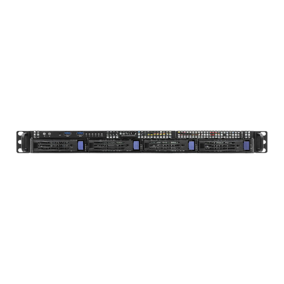
5
Front Panel
1
2
No.
Description
1
Control Panel Buttons and LEDs
2
2 x USB 3.2 Gen1 Ports
3
4 x 3.5" Hot-Swap HDD Trays
4
1 x Slim ODD Carrier (Optional)
2
1
5
6
7
8
11
12
13
No.
Description
8
HDD Backplane Board (BPB)
9
Front Panel Board (FPB)
10
2.5" SATA HDD
11
2.5" SATA HDD
2.5" SATA HDD or Slim Optical Disc
12
Drive (ODD) (optional)
13
4 x 3.5" SATA HDDs (Hot-swapable)
4
3
1
Replace Server Board
Carefully unplug all cables and release
1
thumbscrews on the ser ver board to
remove them from the barebone.
Align the replaced server board with the
2
mounting holes
A f f i x t he screws clock w ise into t he
3
mounting holes in all of the corners of
the server board.
Do not over-tighten the screws
Control Panel
3
4
2
3
1
NMI
RST
ID
No.
Description
1
ID Button and LED
2
Power Button and LED
3
NMI (Nonmaskable Interrupt) Button
4
System Reset Button
5
LAN1, LAN2, LAN3, LAN4 Activity LED
6
HDD Status LED
7
System Status LED
I/O Panel
4
2
4
1
3
No.
Description
1
VGA Port (VGA)
2
Serial Port (COM1)
3
USB 3.2 Gen1 Ports (USB3_1_2)
4
LAN RJ-45 Port (IPMI_LAN)
5
1G LAN RJ-45 Port (LAN1)
6
Rear Panel
1
2
No.
Description
1
2 x Power Supply Units (PSU)
2
Rear Vent
3
I/O Shield (depends on the specification of the server board)
4
PCI Express Slot (for the riser card)
www.asrockrack.com
5
6
7
SYS
L3
L4
L1
L2
6
5
7
8
No.
Description
6
1G LAN RJ-45 Port (LAN2)
7
10G LAN RJ-45 Port (LAN3)
8
10G LAN RJ-45 Port (LAN4)
9
UID Switch (UID1)
3
4
9
Advertisement

Related Manuals for ASROCK Rack 1U4LW-C262/2L2T RPSU


Summary of Contents for ASROCK Rack 1U4LW-C262/2L2T RPSU
- Page 1 1U4LW-C262/2L2T RPSU www.asrockrack.com Replace Server Board The User's Manual is available for download from the ASRock Rack's official website at http:// www.asrockrack.com. Carefully unplug all cables and release Take note of the following precautions before installing the components or change any settings.
- Page 2 Quick Installation Guide 1U4LW-C262/2L2T RPSU www.asrockrack.com Remove and Install Top Cover Remove HDD Tray and Install Hard Drive Removing the Server Top Covers Installing the Server Top Covers Installing a 3.5” Hard Drive to the Hard Drive Tray Front Panel-Installing the HDD assembly 1.
Need help?
Do you have a question about the 1U4LW-C262/2L2T RPSU and is the answer not in the manual?
Questions and answers