Table of Contents
Advertisement
Quick Links
Advertisement
Table of Contents

Subscribe to Our Youtube Channel
Related Manuals for Danfoss EC-LCL1200B-350


Summary of Contents for Danfoss EC-LCL1200B-350
- Page 1 User Guide Heavy duty filter EC-LCL1200B-350 www.danfoss.com...
- Page 2 User Guide EC-LCL1200B-350 Revision history Table of revisions Date Changed September 2024 First edition 0101 © Danfoss | September 2024 BC500439527544en-000101...
-
Page 3: Table Of Contents
High voltage connections..............................44 Low voltage connections...............................44 Operation Operation conditions..................................48 Condition monitoring during operation..........................48 Maintenance Regular maintenance................................... 49 Cooling system maintenance..............................50 Cleaning......................................50 Dismounting and disposal of the electric device Troubleshooting Aftersales © Danfoss | September 2024 BC500439527544en-000101 | 3... - Page 4 User Guide EC-LCL1200B-350 Contents Service policy....................................56 © Danfoss | September 2024 BC500439527544en-000101...
-
Page 5: General Information
D8, DIN 125, zinked Conformity according to standards The electric device has been designed in accordance with the essential parts of the following directives and to meet the requirements of the standards: © Danfoss | September 2024 BC500439527544en-000101 | 5... -
Page 6: Warranty
Applicable part: Category C3 conductive EMC limits (DUT I > 100 A) Warranty Danfoss offers warranty against defects in workmanship and materials for its products for a period of twelve (12) months from commissioning or eighteen months (18) from delivery (Incoterms-EXW), whichever occurs first. -
Page 7: Responsibility Of The Manufacturer
Rated ambient temperature °C Resistance Ω Responsibility of the manufacturer Danfoss is responsible for the safety, reliability and performance of the electric device only if: • Handling, mounting, installation, operation and maintenance are carried out by qualified and authorized service personnel. •... -
Page 8: Safety Information
It indicates a hot device that could cause burns to a person. The symbol also indicates that the device should be placed and installed so that contact with its potentially hot surface is not possible. © Danfoss | September 2024 BC500439527544en-000101... -
Page 9: Personal Protective Equipment
Use cut resistant gloves when you handle and maintain the electric device. There is a risk of cut injuries. Use protective footwear when you lift or move the electric device! Foot injuries could be caused if lifting system or lifting brackets fail. © Danfoss | September 2024 BC500439527544en-000101 | 9... -
Page 10: Safety Features
EMC Directive 2014/30/EU. Installation safety Only trained and qualified personnel familiar with the relevant safety requirements can install the electric device. If the electric device is installed incorrectly it may lead to safety hazard. © 10 | Danfoss | September 2024 BC500439527544en-000101... - Page 11 Do not attempt to repair the electric device. In the case of suspected fault or malfunction, contact Danfoss or Danfoss authorized service center for further assistance. When you install the electric device, make sure that the cooling system and the used coolant meet the specifications of the manufacturer.
-
Page 12: Operation Safety
Do not use the electric device without correctly dimensioned and operating cooling system. Maximum operation temperature must not be exceeded to avoid permanent damage to the electrical device. The requirements of this user guide and other related instructions and standards must be followed. © 12 | Danfoss | September 2024 BC500439527544en-000101... - Page 13 The electric device can only be used in the applications it is intended for. The rated nominal values and operational conditions are shown in the rating plate. © Danfoss | September 2024 BC500439527544en-000101 | 13...
-
Page 14: Product Overview
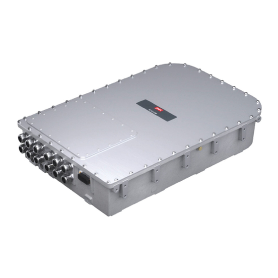
874 mm 178 mm Main components L1 connection M32 x 1,5 threads or cable gland (Optional) L2 connection M32 x 1,5 threads or cable gland (Optional) Coolant inlet/outlet G3/4; DEEP 18,5 mm © 14 | Danfoss | September 2024 BC500439527544en-000101... -
Page 15: Intended Use Of The Electric Device
Using the electric device, making adjustments and maintenance without first reading the user guide. • Exceeding the designed limits during the operation. • Using non-original service parts of wrong material causing corrosion problems and mechanical failures in time. © Danfoss | September 2024 BC500439527544en-000101 | 15... -
Page 16: System Introduction
• Storing the electric device without proper support that prevents overturning and falling. For product specific and up to date information see product data sheets at https://www.danfoss.com/. System introduction Danfoss provides electric drivetrains for applications in heavy mobile work machines, marine vessels and transportation vehicles. -
Page 17: Cooling
The rating plate contains device rating and identification details. The figure below shows an example of a rating plate. For exact information, see the product-specific data sheet at https:// or the rating plate on the electric device. www.danfoss.com/ © Danfoss | September 2024 BC500439527544en-000101 | 17... -
Page 18: Tightening Torques
For correct and safe operation, it is essential to use specified tightening torques for the electric device screws. Tightening torques (screw preloads) used in the electric device are shown in the Table below. © 18 | Danfoss | September 2024 BC500439527544en-000101... - Page 19 Grounding cable mounting screws, M8 12 Nm Cable gland (tighten from the frame of the gland) 15 Nm Coolant connection Tightening torque according to the cooling connector manufacturer specification. Maximum tightening torque 50 Nm © Danfoss | September 2024 BC500439527544en-000101 | 19...
-
Page 20: Transportation And Storage
Inspect the electric device and the package immediately upon arrival. Ensure that the rating plate data in the cover letter complies with the purchase order. All external damage in the package or in the electric device must be photographed and reported to Danfoss immediately. Lifting Use correct, adequately dimensioned lifting devices and inspect them before lifting. - Page 21 See the rating plate and data sheets for weight information. Lift the electric device using the correct lifting lugs/eyes only. See the lifting Figures in this Chapter. Do not go under a lifted load. Correct lifting and incorrect lifting © Danfoss | September 2024 BC500439527544en-000101 | 21...
- Page 22 User Guide EC-LCL1200B-350 Transportation and storage Vertical lifting, front end • M10 lifting eye (max. 16 mm deep), 2 pcs (not included in the delivery) Vertical lifting, back end © 22 | Danfoss | September 2024 BC500439527544en-000101...
-
Page 23: Handling
Always store the electric device indoors. The storage temperature should preferably be above -20°C and the relative humidity less than 60 %. Storage conditions must be dry and dust free. Make sure that the cabling and cooling connections are plugged and sealed before storage. © Danfoss | September 2024 BC500439527544en-000101 | 23... - Page 24 User Guide EC-LCL1200B-350 Transportation and storage The electric device must not be subjected to any external vibrations during storage to avoid possible hidden structural damages. © 24 | Danfoss | September 2024 BC500439527544en-000101...
-
Page 25: Installation
The reference value 100 MΩ has to be exceeded at reference ambient temperature +25°C (measured with 500 V / 1 min insulation resistance test). Contact Danfoss Editron service if the reference value is not exceeded. Measuring the insulation resistance Insulation resistance testers generate lethal voltages. - Page 26 The insulation resistance is measured between terminals and the converter enclosure. When measuring the main circuit, the auxiliary circuits are grounded. When measuring the auxiliary circuits, the main circuit is grounded. The following tables show test conditions and pass criteria for the EC-LCL1200B-350 heavy duty filter. Main circuit Test voltage...
-
Page 27: Mechanical Installation
The electric device must be mounted in a way that no other object or structure, which can cause compression, pull, torsion, rotation etc., touches the enclosure of the electric device. In addition, the electric device should not be used to support any other structure of the system. © Danfoss | September 2024 BC500439527544en-000101 | 27... - Page 28 Breather plug Make sure that the breather plugs (2 pcs) are clean and the selected installation place and mounting direction do not allow water, dust or dirt to block them. © 28 | Danfoss | September 2024 BC500439527544en-000101...
-
Page 29: Installation Procedure
X1-connector can break. See the Figure below for more information. Always check the compatibility of the X1-connector and the counterpart. Never alter the connector in any way. Preparations © Danfoss | September 2024 BC500439527544en-000101 | 29... - Page 30 8. Dismount the connection box lid (item 1 in the figure below). 9. Connect the power cabling. Refer to Chapter Electrical connections on page 32. 10. Install the connection box lid. 11. Mount the safety plate. © 30 | Danfoss | September 2024 BC500439527544en-000101...
-
Page 31: Cooling Connections
When selecting cooling liquid nipples, choose nipples that can resist galvanic corrosion. To prevent damage to the cooling connectors, refer to the documentation of the manufacturer for the correct tightening torque of the cooling liquid nipples. © Danfoss | September 2024 BC500439527544en-000101 | 31... -
Page 32: Recommended Coolants
Before you start the electrical installation, make sure that the environment is dry and free from conductive dust particles. Minimum cable temperature withstand is +95°C. © 32 | Danfoss | September 2024 BC500439527544en-000101... -
Page 33: Grounding
Miniature Circuit Breaker (MCB). Put correctly rated fuses or MCB in the mains supply of the electrical device: obey the local legislation and recommendations. © Danfoss | September 2024 BC500439527544en-000101 | 33... - Page 34 Grounding connection M8 (12 mm deep). Refer to Main dimension drawing if necessary. Safety grounding points and protective earth conductor Touch current in the protective earth conductor exceeds 3,5 mA AC and 10 mA DC. © 34 | Danfoss | September 2024 BC500439527544en-000101...
-
Page 35: Cable Gland Assembly And Power Line Connection
All power connections must be secured with cable lugs and cable glands. EMC- shielded cable glands are used in all Danfoss products for the power connections. Make sure that the low voltage cable (control signal cable) shield is also grounded from the both ends. - Page 36 Cable harness connection with the cable lug and the cable gland (for illustration only) It is recommended to use screw size M8 x 16 and a washer combination of wave and regular washers. © 36 | Danfoss | September 2024 BC500439527544en-000101...
- Page 37 (length B is from 10 to 15 mm) off the cable as shown in the figure. Distance A depends of the length of the used cable lug. Measure with the cable lug that is used and cut to suitable length. © Danfoss | September 2024 BC500439527544en-000101 | 37...
- Page 38 4. Insert the cable to the cable gland with slight turning motion. This helps the cable go through the spring inside the cable gland. Push the cable gland against the sheath of the cable as shown in Figure below. © 38 | Danfoss | September 2024 BC500439527544en-000101...
- Page 39 Cut the braid screen 6. Cut a piece of length D of the inner sheath shown in Figure below. The length D must be equal to the length of the cable lug body. © Danfoss | September 2024 BC500439527544en-000101 | 39...
- Page 40 8. Cut piece of shrink tube and shrink it over the cable lug and braid screen as shown in Figure below. This is done to keep the braid screen in place and for extra insulation. © 40 | Danfoss | September 2024 BC500439527544en-000101...
- Page 41 12. Repeat the procedure to the other cables and connections. 13. Close the power terminal cover and install the connector shield. 14. Make sure that the power cable shields are grounded properly. © Danfoss | September 2024 BC500439527544en-000101 | 41...
- Page 42 Cable lug Druseidt with narrow http://www.druseidt.de flange 03906 Cable gland http://www.pflitsch.de Pflitsch blueglobe TRI bg 225ms tri Screw DIN 912 M8x20 Washer DIN 2093, 8.2 x 16 x 0.9 Washer DIN 125 D8 © 42 | Danfoss | September 2024 BC500439527544en-000101...
-
Page 43: Cabling And Wiring
Use only EMI shielded power cables to make sure the correct operation of the electric device and to minimize the radiated emissions. Cable shields must be connected to the electric device ground at both ends of the cable. All Danfoss products use EMI shielded cable glands for power connections. © Danfoss | September 2024... -
Page 44: High Voltage Connections
POWER_ON (see Figure Disconnecting the power supply in this section). A safe value for t is 5 seconds. See the correct signal connections and product specific pin-layout from product data sheets at http://www.danfoss.com. © 44 | Danfoss | September 2024 BC500439527544en-000101... - Page 45 Detailed and up to date information can be found at the manufacturer's website. Connector assembly should be done according to the connector manufacturer's instructions (for example contact crimping). For IP6K9K, the signal connector requires the use of backshell. See connector manufacturer's website for further details. © Danfoss | September 2024 BC500439527544en-000101 | 45...
- Page 46 High voltage interlock loop can be used to detect the removal of the signal connectors on EC- C1200-450 and EC-LCL1200B units by using a Controller or PLC to feed a current or PWM signal through the units and monitoring HVIL output. © 46 | Danfoss | September 2024 BC500439527544en-000101...
- Page 47 Sufficient time should elapse between bringing the POWER_ON voltage down and bringing VIN_P down. Signals for monitoring, diagnostics and set-up Monitoring, diagnostics and setting up of the electric device takes place through the converter. For more information, see User Guide EC-C Software. © Danfoss | September 2024 BC500439527544en-000101 | 47...
-
Page 48: Operation
32. • Maximum enclosure temperature +90°C (in worst conditions). If the operation limits are exceeded and the electric device is damaged, please contact local Danfoss representative. Condition monitoring during operation Risk of permanent damage to the electric device. Use the electric device only if the technical guidelines and ambient conditions given in this user guide and in the data sheet are met. -
Page 49: Maintenance
Regular maintenance Do not disassemble the electric device. You can do only procedures described in this user guide. For further information contact Danfoss representative. Only trained and qualified personnel that are familiar with the relevant safety requirements can do any maintenance to the electric device. -
Page 50: Cooling System Maintenance
Weekly Monthly Yearly General Operation Abnormal phenomenon, for example noise or construction heating. If clearly increased, contact Danfoss representative. Mounting Tightness of the screws. Tighten to proper value if necessary. Applies to screws that are presented in this user guide. See Chapter Tightening torques on page 18. - Page 51 Risk of electric shock if the electric device is cleaned against instructions allowing water to go in to the electric device. Keep the electric device clean. For cleaning, use non-abrasive and non-corrosive cleaning products. Make sure that the detergent can be used for aluminum. © Danfoss | September 2024 BC500439527544en-000101 | 51...
-
Page 52: Dismounting And Disposal Of The Electric Device
11. Lift of the electric device according to Chapter on page 20. Lifting Disposal of the electric device Dispose of the electric device and any of its parts by appropriate means in accordance with local laws and regulations. © 52 | Danfoss | September 2024 BC500439527544en-000101... - Page 53 User Guide EC-LCL1200B-350 Dismounting and disposal of the electric device Electric device must not be opened (excluding the connection box lid). Any attempt causes loss of warranty. © Danfoss | September 2024 BC500439527544en-000101 | 53...
-
Page 54: Troubleshooting
Do not try to repair the electric device. In the case of suspected fault or malfunction, contact Danfoss or authorized service centre for further assistance. For the reason of general safety and correct operative actions, read the instructions carefully before you start any analyses or work with the electric device. - Page 55 Poor control signal Inspect the X1-connector mounting and individual wire contacts (low voltage) connection. Ensure correct signal cabling (shielding, twisted pair). See section Electrical installation for more information. © Danfoss | September 2024 BC500439527544en-000101 | 55...
- Page 56 User Guide EC-LCL1200B-350 Aftersales Service policy For further information, go to https://danfosseditron.zendesk.com/hc/en-gb or send email to editron.service@danfoss.com. © 56 | Danfoss | September 2024 BC500439527544en-000101...
- Page 57 Phone: +86 21 2080 6201 Danfoss can accept no responsibility for possible errors in catalogues, brochures and other printed material. Danfoss reserves the right to alter its products without notice. This also applies to products already on order provided that such alterations can be made without subsequent changes being necessary in specifications already agreed.
Need help?
Do you have a question about the EC-LCL1200B-350 and is the answer not in the manual?
Questions and answers