Table of Contents
Advertisement
Quick Links
Advertisement
Table of Contents

Related Manuals for EK-Quantum Power2 Kit P360 Series


Summary of Contents for EK-Quantum Power2 Kit P360 Series
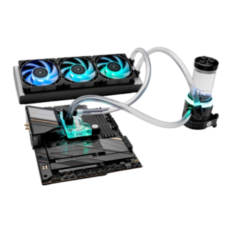
- Page 1 EK-Quantum Power Kit P360 Series LIQUID COOLING KIT INSTALLATION MANUAL...
-
Page 2: Method
Please note the installation of the product is intended to be undertaken by an adequately trained and experienced person. You are installing the product at your own risk. If you are not properly trained or experienced or feel unsure about the installation procedure, please refrain from installing the product yourself and contact our tech support for assistance. -
Page 3: Table Of Contents
TABLE OF CONTENT BOX CONTENTS TROUBLESHOOTING REQUIRED TOOLS CLEANING GUIDE PREVENTIVE STEPS QUICK INSTALLATION GUIDE SUPPORT AND SERVICE RADIATOR SPACE REQUIREMENTS SOCIAL MEDIA INSTALLATION TIPS FOR NOVICES LIQUID COOLING SYSTEM GENERAL INFORMATION ON CPU WATER BLOCK COMPATIBILITY INTEL LGA 1700 INTEL LGA 1700 CPU MOUNTING MECHANISM AMD AM5 AMD AM5 CPU MOUNTING MECHANISM... -
Page 4: Box Contents
BOX CONTENTS Pump-Reservoir Unit (1x) CPU Water Block EK- Quantum Surface EK-Loop Fan FTP (3x) (Intel® / AMD®) (1x) Radiator (1x) EK-RES X3 - Holder 60 mm (1x) EK-Torque STC Fittings (6x) EK-Torque angled Fittings (2x) EK-CryoFuel Clear (concentrate 100 mL) (1x) Tube (1x) Fan Cable Y-splitter (1x) EK-Loop Foldable Filling... -
Page 5: Required Tools
EK-Loop Soft Tube Cutter (1x) EK-CryoFuel Dye Pack (1x) EK-ATX Bridging Plug EK-Loop Uni Pump (24 pin) (1x) Reservoir Bracket (1x) REQUIRED TOOLS Phillips-head Screwdriver Mixing Bottle 1L Bottle of distilled Water Scissors - 5 -... -
Page 6: Radiator Space Requirements
RADIATOR SPACE REQUIREMENTS 405 mm 37 mm 33 mm 105 mm 17 mm 23 mm 15 mm 22 mm 22 mm ф23 mm - 6 -... -
Page 7: Installation Tips For Novices
INSTALLATION TIPS FOR NOVICES 1. To lower the shipping cost, we have decided to enclose the coolant 5. If you spot any leaks, turn off the power immediately. concentrate only. Therefore, you need to provide 1 liter (1L) of 6. Optimize tube length to prevent excessive bending and kinking of distilled water. -
Page 8: General Information On Cpu Water Block Compatibility
GENERAL INFORMATION ON CPU WATER BLOCK COMPATIBILITY INTEL LGA 1700 This CPU liquid cooling unit is pre-assembled for use with modern 94.5 mm 15.5 mm Intel desktop socket-type motherboards. By default (out of the box) 78 mm this water block supports the Intel LGA 1700 socket. INTEL LGA 1700 CPU MOUNTING MECHANISM Allen Key 2 mm (1 pc) -
Page 9: Amd Am5
AMD AM5 89 mm This CPU liquid cooling unit is pre-assembled for use with modern 12.5 mm AMD desktop socket-type motherboards. By default (out of the box) this water block supports the AMD AM5 socket. AMD AM5 CPU MOUNTING MECHANISM Allen Key 2 mm (1 pc) Allen Key 2.5 mm (1 pc) Thermal grease (1 pc) -
Page 10: Installing The Cpu Water Block
INSTALLING THE CPU WATER BLOCK INTEL LGA 1700 STEP 1 Non-abrasive Cloth If already installed, please remove the motherboard from your computer and place it on an even surface. STEP 2 Install the CPU and clean the IHS surface using a non-abrasive cloth or Q-tip as shown in the illustration. - Page 11 STEP 4 Unscrew the pre-installed backplate from the backside of the CPU using an Allen Key 2.5 mm and save it for the later steps. STEP 4 STEP 5 Before placing the water block, it is mandatory to remove the protective foil from the backside.
- Page 12 STEP 6 Position the CPU Water Block onto the Motherboard. Make sure to align the holes (as shown in the picture). Make sure to double-check the layer of the Thermal Grease before placing the water block onto the motherboard. STEP 6 STEP 7 TOP OF THE After placing the water block, the stored backplate must be...
-
Page 13: Amd Am5
STEP 8 : With EK-Velocity series water blocks, it is mandatory to use the bottom port as the INLET. Mixing the ports may result in poor thermal performance of the water block. Tighten the fittings in a clockwise OUTLET direction until the gasket underneath is compressed. PORT After installing the CPU water block, the motherboard can be installed into the PC Chassis. - Page 14 STEP 3 NON-ABRASIVE CLOTH Install the CPU and clean the IHS surface using a non-abrasive cloth or Q-tip as shown in the illustration. STEP 3 STEP 4 Apply the enclosed thermal grease (thermal compound) on the CPU heat spreader – IHS – as shown in the image. The layer of the thermal compound must be thin and even in thickness over the entire surface of the IHS.
- Page 15 STEP 5 Before placing the water block, it is mandatory to remove the protective foil from the backside. PROTECTIVE STICKER STEP 5 STEP 6 Position the CPU Water Block onto the Motherboard. Make sure to align the holes (as shown in the picture). Before placing the water block, it is mandatory to remove the protective foil from the backside.
- Page 16 STEP 7 Secure the water block from the backside of the motherboard using the included Tx7 L-Shaped wrench. Tighten the mounting screws in an anti-clockwise direction. Start fastening the screws in a cross pattern. Do not tighten fully until all of the screws are partially screwed in.
-
Page 17: Installing The Radiator And Fans
INSTALLING THE RADIATOR AND FANS Before positioning the fans on the radiator, decide if you want them to serve as the hot air exhaust (Method 1 - when fans are placed on M4 x 30 PHILLIPS HEAD SCREW the exhaust) or to receive the coldest air possible (Method 2 - when they’re placed on the air inlet). - Page 18 STEP 3 Prepare your suitably-sized PC chassis for the installation of the radiator unit. The position of the unit in the chassis depends on its size, fan mounting holes, and the hardware that is installed. You must make sure the unit fits into the case. Usually, cases already have standard pre-drilled fan-mounting holes, and you should look for those with a spacing of 105mm (for standard 120mm computer cooling fans) or 125mm (for 140mm cooling fans).
- Page 19 Make sure to close the remaining ports. Tighten the fitting barbs in the clockwise direction. The installation of the radiator and fans is now complete. OPTIONAL: EK-Quantum Power Kit also comes with two pieces of EK-Torque 90˚ Angled Fittings, which can be installed on the Pump-Reservoir Combo unit, CPU unit, or Radiator.
- Page 20 STEP 2 Connect the Fan-s in series with the “daisy chain”. Make sure to turn the connectors correctly. MALE CONNECTOR FEMALE CONNECTOR STEP 2 STEP 3 Align the holes of the radiator and fans with the ones in the PC M4 x 30PHILLIPS HEAD SCREW chassis.
- Page 21 The installation of the radiator and its cooling fans is now complete. OPTIONAL: EK-Quantum Power Kit also comes with two pieces of EK-Torque 90˚ Angled Fittings, which can be installed on the Pump-Reservoir Combo unit, CPU/GPU unit, or Radiator.
-
Page 22: Installing The Pump-Reservoir Combo Unit
INSTALLING THE PUMP-RESERVOIR COMBO UNIT MOUNTING MECHANISM RESERVOIR TOP (3 PORTS) Tube HD 12/16 EK-PLUG G1/4 Acetal OR 16,1 x 1,6 (41,00 mm) (1 pc) (1 pc) (1 pc) 104MM/4.09’’ RESERVOIR TUBE Allen Key 2 mm Allen Key 2.5 mm M4 PVC Washer (1 pc) (1 pc) - Page 23 STEP 1 The EK-Quantum Power Kit comes with a combined pump and reservoir unit with a pre-installed antivibration holder. PUMP-RESERVOIR COMBO UNIT Take the unit and place it on the EK-Loop Uni Pump Reservoir Bracket, as shown in the picture.
- Page 24 FITTINGS FITTING The installation of the pump-reservoir unit is now complete. BARB OPTIONAL: EK-Quantum Power Kit also comes with two pieces of EK-Torque 90˚ Angled Fittings, which can be installed on the FITTING Pump-Reservoir Combo unit, CPU unit, or Radiator.
-
Page 25: Connecting The Tubing
CONNECTING THE TUBING If you are adding another unit to your water-cooling loop, please check the chapter System Expansion Possibilities. COLD AIR STEP 1 CPU WATER In order to successfully route your tubing, we recommend you check BLOCK the liquid cooling scheme. RADIATOR WITH FANS HOT AIR... - Page 26 STEP 3 If you assembled the components according to this installation manual, all the compression fittings should have already been installed. FITTING BARB To fit the tubing onto the compression fittings, you will have to remove fitting rings by rotating them in a counter-clockwise direction.
-
Page 27: Electrical Installations
STEP 5 Slide the fitting ring toward the fitting barb and tighten it in a clockwise direction as far as it goes. Repeat the procedure on all fittings to connect your liquid cooling loop. STEP 5 ELECTRICAL INSTALLATIONS CONNECTING THE PUMP-RESERVOIR UNIT The EK-D5 PWM pump has two connectors.. -
Page 28: Connecting The Fans
CONNECTING THE FANS MALE CONNECTOR STEP 1 From the fan box, take the extension cable. Connect the female connector from the extension cable to the male connector from the fan. *Make sure all fans are properly connected! FEMALE CONNECTOR Make sure to turn the Female connector correctly. STEP 1 - 28 -... -
Page 29: Recommended Filling And Leak Testing Procedure
STEP 2 Connect the 4-pin fan connector from the extension cable directly FAN CONNECTOR to the CPU fan header on the motherboard. We recommend using the CPU fan header. On the majority of motherboards, these headers usually offer the best PWM regulation. STEP 2 RECOMMENDED FILLING AND LEAK TESTING PROCEDURE... -
Page 30: Connecting The Fans, Pump And Cpu D-Rgb Lights
CONNECTING THE FANS, PUMP AND CPU D-RGB LIGHTS STEP 1 Connect the 3-pin D-RGB LED connector from the pump-reservoir unit, water block, and fans to the D-RGB header on the motherboard. The lights will work if the pin layout on the header is as follows: +5V, D-RGB CONNECTOR Data, Empty, Ground. -
Page 31: Filling The System For The First Time
FILLING THE SYSTEM FOR THE FIRST TIME STEP 1 Preparing the Cooling Liquid. The coolant comes in the concentrated form. To prepare the cooling liquid, you must take 100mL of clear coolant concentrate (comes DISTILLED enclosed with the Kit) and mix it with 900mL of distilled water. WATER Make sure you mix it properly before pouring it into your water cooling loop. - Page 32 STEP 4 When you turn on the power supply, the coolant should be pushed from the reservoir toward other water cooling components. Therefore, you have to fill the coolant continuously while the pump is running. Alternatively, you can cycle the power supply by turning it ON and OFF every few seconds to speed up the air bleeding process.
-
Page 33: Draining The Loop
DRAINING THE LOOP STEP 1 Before disassembling the water cooling loop, it is mandatory to turn off your computer and pull the power cord from the socket. Prepare some paper towels and stack them over the hardware. Unscrew the four (4) M4 nuts securing the EK-Loop Uni Pump Reservoir Bracket to the PC chassis. -
Page 34: System Expansion Possibilities
SYSTEM EXPANSION POSSIBILITIES The best part of having a custom water-cooling loop is that the system can be expanded, and its cooling capacity extended almost without limitations. For maximum performance, the rule of thumb is to use at least one 120mm radiator (section) per each water- cooled component plus one additional radiator. - Page 35 STEP 2 Measure the length of the tube that will connect the CPU to the GPU water block, and the GPU water block to the pump-reservoir unit. You can use the EK-Loop Soft Tube Cutter or a pair of scissors to cut the tube. You may also need additional tubing to connect the water block.
-
Page 36: Maintenance Tips
MAINTENANCE TIPS In order to obtain the best performance across the entire lifespan of the product, it is crucial to follow these maintenance tips. 1. DUST REMOVAL It is mandatory to clean the dust every 2-3 months. EK recommends using a vacuum cleaner or compressed air to blow the dust away. -
Page 37: Troubleshooting
TROUBLESHOOTING Exceedingly high CPU temperatures are usually the symptom of a case you have the water block with a translucent acrylic top, this malfunctioning liquid cooling loop, assuming the contact between inspection can be done without disassembling the system. the CPU heat spreader and water block itself is adequate, and that the water is appropriately cooled within the radiator. -
Page 38: Cleaning Guide
CLEANING GUIDE Liquid cooling parts can be disassembled for cleaning Cleaning the nickel-plated copper should consist of the following: purposes on an occasional basis. Your warranty will not • rinse the nickel-plated copper under warm water; be void upon disassembly of the water block, but you will •... -
Page 39: Support And Service
SUPPORT AND SERVICE For assistance please contact: http://support.ekwb.com/ EKWB d.o.o. Pod lipami 18 1218 Komenda Slovenia - EU SOCIAL MEDIA EKWaterBlocks @EKWaterBlocks ekwaterblocks EKWBofficial ekwaterblocks...
Need help?
Do you have a question about the Power2 Kit P360 Series and is the answer not in the manual?
Questions and answers