Table of Contents
Advertisement
Quick Links
Contents
1. Introduction
2. Setup
3. Wiring
4. Initial Connection to ProtoNode
5. Setup Web Server Security
6. Setup ProtoNode
7. Setup Energy Management
System Network
8. Troubleshooting
9. Additional Information
10. ProtoNode Information
11. Installation Details
12. LonWorks Points List
Appendix
A. "A" Bank DIP Switch Settings
B. Grid Field Server Manager Setup
Universal Gateway
LonWorks ProtoNode
Instruction Manual
Application
The Universal Gateway (LonWorks ProtoNode) provides
5
monitoring, remote setpoint, firing rate and burner on/off control
7
to the Energy Management Systems/ Building Automation
System/ Building Management System (EMS). The Universal
11
Gateway ProtoNode is compatible with the following brands and
models:
25
Burnham Commercial Models: Products using Sage Boiler
Control (SBC™)
28
Bryan Boilers Models: BFIT, FreeFlex, boilers using following
32
control components: RWF40, RWF55, RM7800, LMV36,
LMV52, PD765, LMV2_3, YB110
37
Thermal Solutions Models: APEX, AMP, Evolution, Arctic,
Conductor
40
U.S. Boiler Company Models: Alpine, ASPEN, ALTA, Citadel
45
Velocity Boiler Works Models: Phantom-X, Raptor, Phantom
II, Phantom-XL
50
There are two Universal Gateway options:
52
ProtoAir: Provides BACnet MS/TP, BACnet/IP, N2, Modbus
TCP communications, refer to "Universal Gateway ProtoAir"
55
Instruction Manual.
LonWorks ProtoNode: Provides LonWorks communication.
Intent
80
This document provides the necessary information to facilitate
Gateway installation. This Instruction Manual includes practical,
83
installation and setup detailed information. The intended users
are contractors and factory support personnel.
FPC-N35-0817
LonWorks ProtoNodes
Part Number: 106417-05
Rev A, 7/24
Advertisement
Table of Contents
Troubleshooting

Related Manuals for FieldServer LonWorks ProtoNode


Summary of Contents for FieldServer LonWorks ProtoNode
- Page 1 Universal Gateway LonWorks ProtoNode Instruction Manual Contents Application The Universal Gateway (LonWorks ProtoNode) provides 1. Introduction monitoring, remote setpoint, firing rate and burner on/off control 2. Setup to the Energy Management Systems/ Building Automation System/ Building Management System (EMS). The Universal 3.
- Page 2 The following term is used throughout this manual to bring attention to special instructions: NOTICE: Indicates special instructions on installation, operation, or service which are important but not related to personal injury hazards. NOTICE: If Building Automation System input fails, some models and controls will revert to local start command, setpoint, and firing rate.
-
Page 3: Table Of Contents
4.2 Use the ProtoNode Web Configurator to setup the Gateway ................... 25 Changing the Subnet of the Connected PC ....................... 25 4.2.1 Changing the IP Address of the ProtoNode with FieldServer Toolbox ..............26 4.2.2 4.3 Connecting to the ProtoNode Web Configurator ....................28 5 Setup Web Server Security .................... - Page 4 Appendix A. “A” Bank DIP Switch Settings ................81 Appendix B. Grid FieldServer Manager Setup ................84 Appendix B.1. Choose Whether to Integrate the FieldServer Manager ................84 Appendix B.2. User Setup ............................85 Appendix B.3. Registration Process ..........................87 Appendix B.4.
-
Page 5: Introduction
INTRODUCTION Universal Gateway (ProtoNode) is an external, high performance Energy Management System (EMS) multi-protocol gateway that uses the FieldServer ProtoNode Technology. The ProtoNode can support multiple boilers/water heaters. It has been pre-programmed to communicate between boiler devices listed in Table 1-1 and LonWorks®... -
Page 6: Universal Gateway Available Configurations
Universal Gateway Available Configurations The ProtoNode is shipped with the below listed configurations pre-configured and loaded. There is no need to download any configuration. The user simply selects the configuration from a list or Auto- Discovers the configuration. Table 1-1: Universal Gateway Available Configurations BACnet, N2 Type Available Profiles... -
Page 7: Setup
SETUP Each ProtoNode has a unique part number located on the underside of the unit. This number should be recorded, as it may be required for technical support. The number is shown below: Table 2-1: ProtoNode Part Number Model Part Number ProtoNode LER - LonWorks FPC-N35-0817 Boiler Setup... -
Page 8: Rwf40, Lmv52, Rm7800, Lmv36, Pd765, Rwf55, Lmv2_3 Or Yb110
2.1.4 RWF40, LMV52, RM7800, LMV36, PD765, RWF55, LMV2_3 or YB110 Refer to the Boiler’s instruction manual for password and menu navigation instructions to make the following settings: Table 2-3: RWF40, LMV52, RM7800, LMV36, PD765, RWF55, LMV2_3 or YB110 Com. Settings Model Port Setting Selection... -
Page 9: Protonode Setup
ProtoNode Setup A-Bank B-Bank S-Bank Figure 2-1: ProtoNode showing DIP switch “Banks” on bottom 2.2.1 Select EMS Protocol Set Dipswitches to match Protocol of EMS. Remove ProtoNode cover and check protocol dip switch settings: • The “S0 – S2” bank of DIP switches on the ProtoNode LER LonWorks are disabled. 2.2.2 Enable Auto-Discovery Table 2-5 describes “S3”... -
Page 10: Commission The Protonode For Lonworks
Table 2-5: ProtoNode Auto-Discovery Settings LonWorks ProtoNode S3 DIP Switch Auto-Discovery Mode Auto-Discovery ON – Build New Configuration Auto-Discover OFF – Load Current Configuration NOTICE: Initial Auto Discovery Cycle All boilers MUST be POWERED and CONNECTED to the ProtoNode before cycling power to the ProtoNode. The ProtoNode will auto discover only connected boilers. -
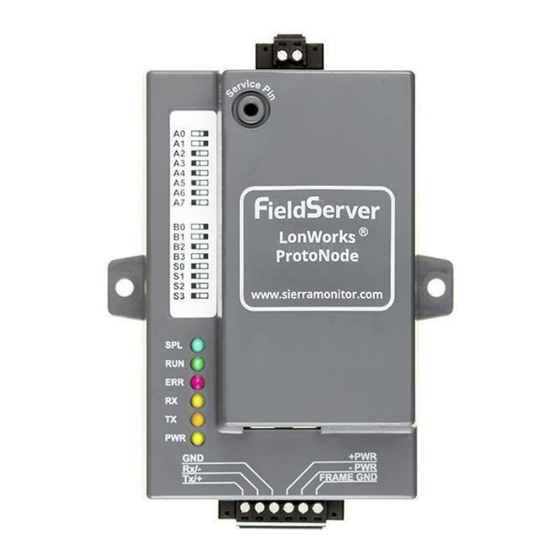
Page 11: Wiring
WIRING ProtoNode Overview Figure 3-1: ProtoNode LonWorks Page 11 of 97 PN: 106417-05... -
Page 12: Wiring To The Protonode 6 Pin Connector
Wiring to the ProtoNode 6 Pin Connector • Pins 1 through 3 are for Modbus RS-485 devices. The RS-485 GND (Pin 3) is not typically connected. • Pins 4 through 6 are for power. Table 3-1: ProtoNode Pin Assignments Device Pins ProtoNode Pin # Pin assignment Pin RS-485 +... -
Page 13: End Of Line Termination Switch For The Modbus Rs-485 Device Network
Figure 3-2: Modbus RS-485 Biasing Switch on the ProtoNode 3.2.2 End of Line Termination Switch for the Modbus RS -485 Device Network • The ProtoNode has an End Of Line (EOL) blue jumper. The default setting for this Blue EOL switch is OFF with the jumper straddling the pins closest to the inside of the board of the ProtoNode. -
Page 14: Thermal Solutions Boiler Control (Tsbc) And Sage Boiler Control (Sbc)
Thermal Solutions Boiler Control (TSBC) and Sage Boiler Control (SBC) • The Modbus communication connects to the same RJ11 port that is used by the boiler-to-boiler communication. • Connect one end of the RJ11 cable to the TSBC and cut off the other end of the cable to access the individual wires of the RJ11 cable. - Page 15 Local /Remote Local /Remote (Typical for each boiler) Bacnet or Contact Contact Lonworks (OPTIONAL) (OPTIONAL) Universal Gateway 2 port RJ11 2 port RJ11 Splitter Splitter (Not Included) (Not Included) Note: Connect wires to RJ11 RJ11 ProtoNode as shown on previous page. TSBC TSBC Control System...
-
Page 16: Apex, Alpine, Aspen, Phantom-X Or Raptor With Panasonic Display
Apex, Alpine, ASPEN, Phantom-X or Raptor with Panasonic Display RS485 GND + PWR RS485 - - PWR ProtoNode RS485 + FRAME GND Apex with Panasonic Display Panasonic GT02 Display Type A RJ45 Wiring Notes 1 – Wire to Brown 2 – Wire to White/Brown ENVIRACOM 3 –... - Page 17 Firing Rate Boiler Firing Rate Boiler BACnet or 4-20mAdc Enable/Disable 4-20mAdc Enable/Disable (Typical for each boiler) Lonworks Demand Contact Demand Contact Apex Boiler Apex Boiler (Typical) (Typical) T-STAT OR EMS CONTACT T-STAT OR EMS CONTACT T-STAT OR EMS CONTACT T-STAT OR EMS CONTACT DHW TEMP SWITCH DHW TEMP SWITCH DHW TEMP SWITCH...
-
Page 18: Apex & Amp/Bfit/Citadel/Phantom-Xl 400-1000L With Concert Display
Apex & AMP/BFIT/Citadel/Phantom-XL 400-1000L with Concert Display Low Voltage Connections RS485 GND RS485 GND + PWR + PWR RS485 - Header RS485 - - PWR - PWR Demand ProtoNode ProtoNode Sensor RS485 + RS485 + FRAME GND FRAME GND Auto Reset External Sensor Limit... -
Page 19: Older Arctic Or Freeflex 1000 With Concert Display
Older Arctic or FreeFlex 1000 with Concert Display Figure 3-12: Older Arctic/FreeFlex 1000 with Concert Modbus RS485 Wiring NOTICE: 1. Arctic/FreeFlex with Concert Display can do both Lead Lag (Sequencer) and EMS communication at the same time. For Arctic/FreeFlex Boilers not equipped with PCBs refer to 4109 profile (Apex, Alpine or ASPEN) wiring. 3. -
Page 20: Arctic, Amp, Freeflex, Bfit & Citadel With Concert Display
Arctic, AMP, FreeFlex, BFIT & Citadel with Concert Display Figure 3-13: Arctic, AMP, FreeFlex, BFIT & Citadel with Concert Modbus RS485 Wiring NOTICE: AMP/BFIT 1. Arctic/FreeFlex, 1000-4000, & Citadel 1250-1500 with Concert Displays can do both Lead Lag (Sequencer) and EMS communication at the same time. 2. -
Page 21: Rwf40 Or Rwf55
RWF40 or RWF55 RWF40 Wiring RWF55 Wiring Figure 3-14: RWF40 and RWF55 Modbus RS485 Wiring NOTICE: • Connect terminal CA (RWF40) or R+ (RWF55) to Pin 1 (RS-485+) on the ProtoNode. • Connect terminal CB (RWF40) or R- (RWF55) to Pin 2 (RS-485-) on the ProtoNode. •... -
Page 22: Rm7800 Series
RM7800 Series Figure 3-15: RM7800 Modbus RS485 Wiring NOTICE: • Connect terminal A (RS-485+) to Pin 1 (RS-485+) on the ProtoNode. • Connect terminal CB RxD / TxD- (RS-485-) to Pin 2 (RS-485-) on the ProtoNode. • CG Ground terminal does not need to be grounded to the RS-485 Ground port of ProtoNode. Page 22 of 97 PN: 106417-05... -
Page 23: Alta, Altac, Phantom Ii, Phantom Combi Ii Control
ALTA, ALTAC, Phantom II, Phantom Combi II Control 3.10 Figure 3-16: ALTA, ALTAC, Phantom II, Phantom Combi II Control Modbus RS485 Wiring The control system has a full featured ability to interface with an Energy Management System (EMS). The control system allows remote control and monitoring via RS485 Modbus or through direct wiring. The EMS connection is separate from the Boiler-to-Boiler communication network and may be used simultaneously. -
Page 24: Conductor Wiring
Conductor Wiring 3.11 + PWR Rx / - - PWR ProtoNode Frame GND Tx / + CN19 RS485-1 PCB-10 Figure 3-17: RM7800 Modbus RS485 Wiring NOTICE: Conductor-to-ProtoNode wiring is a separate Modbus network from Conductor-to-Boiler wiring. The ProtoNode should only be wired to Conductor and EMS. 3.12 ProtoNode LonWorks Wiring •... -
Page 25: Initial Connection To Protonode
Figure 4-1: ProtoNode Ethernet Port There are two methods to access the ProtoNode via Ethernet connection, either by changing the subnet of the connected PC (Section 4.2.1) or using the FieldServer Toolbox to change the IP Address of the ProtoNode (Section 4.2.2). -
Page 26: Changing The Ip Address Of The Protonode With Fieldserver Toolbox
• Click twice 4.2.2 Changing the IP Address of the ProtoNode with FieldServer Toolbox • Ensure that FieldServer Toolbox is loaded onto the local PC. Otherwise, download the FieldServer-Toolbox.zip via the Sierra Monitor website’s Software Downloads. • Extract the executable file and complete the installation. - Page 27 • Select Network Settings in the Configure Device window. • Modify the IP Address (N1 IP Address field) of the gateway Ethernet port. o The following fields may also be changed as needed: Netmask (N1 Netmask field), DHCP Client State (N1 DHCP Client State field), IP Gateway (Default Gateway field) and DNS 1 & 2 (Domain Name Server fields) NOTICE: If the gateway is connected to a router, the Default Gateway field of the gateway should be set to the IP Address of the connected router.
-
Page 28: Connecting To The Protonode Web Configurator
Connecting to the ProtoNode Web Configurator After setting a local PC on the same subnet as the ProtoNode (Section 4.1), open a PC web browser, and enter the IP address of the ProtoNode (default: 192.168.1.24) NOTICE: If the IP Address of the ProtoNode was changed, the assigned IP Address can be discovered using the FS Toolbox utility. -
Page 29: Setup Web Server Security
SETUP WEB SERVER SECURITY Login to the FieldServer The first time the FieldServer GUI is opened in a browser, the IP Address for the gateway will appear as untrusted. This will cause the following pop-up windows to appear. • When the Web Server Security Unconfigured window appears, read the text and choose whether to move forward with HTTPS or HTTP. - Page 30 When the login screen appears, put in the Username (default is “admin”) and the Password (found on the label of the FieldServer). NOTICE: There is also a QR code in the top right corner of the FieldServer label that shows the default unique password when scanned.
-
Page 31: Select The Security Mode
Select the Security Mode On the first login to the FieldServer, the following screen will appear that allows the user to select which mode the FieldServer should use. Figure 5-5: Web Security Selection Page NOTICE: Cookies are used for authentication. -
Page 32: Https With Own Trusted Tls Certificate
Passphrase. • Click Save. • A “Redirecting” message will appear. After a short time, the FieldServer GUI will open. HTTPS with Default Untrusted Self-Signed TLS Certificate or HTTP with Built -in Payload Encryption •... -
Page 33: Setup Protonode
Then click the Profiles Configuration button to go to the Web Configurator page. Figure 6-2: ProtoNode Web Configurator configuration page NOTICE: For Web App instructions to the System View, Data Log Viewer, Event Logger and MSA Grid – FieldServer Manager Start-up Virtual Points functions, see the Guide. -
Page 34: Set Configuration Parameters
Set Configuration Parameters • Ensure that all parameters are entered for successful operation of the gateway. Find the legal value options for each parameter under the Parameter Description in parentheses. • Set Baud rate to match connected device: Table 6-1: ProtoNode Configuration Modbus Parameters Sola, 4109, TSBC, Port Setting Other Devices... -
Page 35: Verify Device Communications
• To add an active profile to support a device, click the Add button under the Active Profiles heading. This will present a drop-down menu underneath the Current profile column. • Once the Profile for the device has been selected from the drop-down list, set Node-ID (Modbus address) for any device attached to ProtoNode. -
Page 36: Commissioning Lonworks Protonode
Commissioning LonWorks ProtoNode Commissioning may only be performed by the LonWorks administrator. To commission the ProtoNode LER LonWorks port, insert a small screwdriver in the commissioning hole on the face of the LER’s enclosure to access the Service Pin. See the illustration on the ProtoNode LER as to which way to toggle the screwdriver during commissioning. - Page 37 • For Windows 7: Go to > > > > Right-click on Local Area Connection > Properties Highlight > • Select: Use the following IP address • Click twice • Open a web browser and go to the following address: IP address of ProtoCessor/fserver.xif •...
-
Page 38: Setup Energy Management System Network
SETUP ENERGY MANAGEMENT SYSTEM NETWORK Navigate to the Network Settings • From the Web App landing page, click the Settings tab on the left side of the screen. Figure 7-1: ProtoNode Web Configurator Landing Page • Click the Network tab that appears to open the Network Settings page. Figure 7-2: Settings Menu •... -
Page 39: Routing Settings
Routing Settings The Routing settings make it possible to set up the IP routing rules for the FieldServer’s internet and network connections. • Click the Add Rule button to add a new row and set a new Destination Network, Netmask and Gateway IP Address as needed. - Page 40 Figure 7-5: Ethernet Page Page 40 of 97 PN: 106417-05...
-
Page 41: Troubleshooting
TROUBLESHOOTING Lost or Incorrect IP Address • Ensure that FieldServer Toolbox is loaded onto the local PC. Otherwise, download the FieldServer-Toolbox.zip via the MSA Safety website. • Extract the executable file and complete the installation. Figure 8-1: ProtoNode Ethernet Port •... -
Page 42: Viewing Diagnostic Information
Viewing Diagnostic Information • Type the IP Address of the FieldServer into the web browser or use the FieldServer Toolbox to connect to the FieldServer. • Click on Diagnostics and Debugging Button, then click on view, and then on connections. -
Page 43: Led Functions
Verify IP Address setting. NOTICE: If the problem still exists, a Diagnostic Capture needs to be taken and sent to support. (Section 8.6 Take Diagnostic Capture with FieldServer Utilities) LED Functions Please see the diagram below for ProtoNode LER LonWorks LED Locations. -
Page 44: No Communication" Troubleshooting Trees
“No Communication” Troubleshooting Trees 8.5.1 General Troubleshooting Whenever a setting is changed (i.e. dipswitches or communication) power should be cycled to the ProtoNode to allow for settings to take effect. 1. Is power connected to boilers and ProtoNode? • Green PWR LED solid on ProtoNode •... -
Page 45: Take Diagnostic Capture With Fieldserver Utilities
• Access the FieldServer Diagnostics page via one of the following methods: ◦ Open the FieldServer FS-GUI page and click on Diagnostics in the Navigation panel ◦ Open the FieldServer Toolbox software and click the diagnose icon of the desired device Figure 8-5: Diagnostic Capture Page •... -
Page 46: Additional Information
To load a new version of the firmware, follow these instructions: 1. Extract and save the new file onto the local PC. 2. Open a web browser and type the IP Address of the FieldServer in the address bar. ◦ Default IP Address is 192.168.1.24 ◦... -
Page 47: Edit The Certificate Loaded Onto The Fieldserver
5.3 HTTPS with Own Trusted TLS Certificate • Click the Save button. Edit the Certificate Loaded onto the FieldServer NOTICE: A loaded certificate will only be available if the security mode was previously setup as HTTPS with own trusted TLS certificate. -
Page 48: Change Fieldserver Password
If changes to the network settings are made, remember to click the Save button. Then power cycle the FieldServer by clicking on the Confirm button in the window and click on the bolded “Restart” text in the yellow pop-up box that appears in the upper right corner of the screen. -
Page 49: System Status Button
Figure 9-4: ProtoNode Lost Connection Page System Status Button The System Status Button can be found on any page of the web apps. This shows the level of alert/functionality for the customer device. This is an aggregate of the Web App page’s resource usage upon the local PC or mobile device, connectivity and device alert level. - Page 50 Figure 9-6: ProtoNode Status NOTICE: If it was selected to opt out of the FieldServer Manager, the Grid FieldServer Manager status will not appear in the System Status window. This means the status will show as green even if the gateway is not connected to the FieldServer Manager.
-
Page 51: Protonode Information
The interconnecting power connector and power cable shall: ◦ Comply with local electrical code ◦ Be suited to the expected operating temperature range ◦ Meet the current and voltage rating for the FieldServer • Furthermore, the interconnecting power cable shall: ◦... -
Page 52: Ordering Information
I&O) Universal Gateway Wiring Harness Kit (Includes device installed with AMP/BFIT 1000-4000 PN: 106433-02 PN: 112316-01 CTD 1250-1500 ARC/FF 1500-6000 wiring harness and I&O) 10.4 ProtoNode Detailed View Figure 10-1: LonWorks ProtoNode Detailed View Page 52 of 97 PN: 106417-05... -
Page 53: Installation Details
11 INSTALLATION DETAILS 11.1 Universal Gateway Wiring Harness Kit (PN: 1 06433-02) This kit is intended for use with the following boilers: AMP/BFIT 1000-4000, CTD 1250 & 1500, Arctic/FreeFlex 1500-6000. • Use the provided ½” long self-drilling screws (PN: 80860743) to mount the ProtoNode inside of the boiler next to PCB-06. -
Page 54: Universal Gateway Enclosure Kit (Pn: 112736-02)
Figure 11-2: ProtoNode Mounting Location for Arctic/FreeFlex 1500-6000 11.2 Universal Gateway Enclosure Kit (PN: 112736 -02) This kit is intended for use with all other boilers and controls not included in the Universal Gateway Kit with Wiring Harness. • Includes the ProtoNode mounted within a 14"x10"x7" plastic enclosure (see Figure 11-3), as well as mounting brackets to mount the enclosure to a wall. - Page 55 Figure 11-3: ProtoNode Kit with Plastic Enclosure Page 55 of 97 PN: 106417-05...
-
Page 56: Lonworks Points List
12 LONWORKS POINTS LIST 12.1 Thermal Solutions Boiler Control (TSBC) & Sage Boiler Control (SBC) Table 12-1: TSBC/SBC LonWorks Points List Modbus Point Name Lon Name Lon SNVT Notes Register Outdoor Air Reset Enable/Disable 00001 nvoOAResEnDs_XXX SNVT_switch Domestic Hot Water Priority 00002 nvoDmHtWtPri_XXX SNVT_switch... - Page 57 Annunciator Remote Temp Fail 00043 nvoAnRemTpFl_XXX SNVT_switch Annunciator Remote In Fail 00044 nvoAnRemInFl_XXX SNVT_switch Annunciator Comm Fail nvoAnComFl_XXX SNVT_switch 00045 Annunciator Low Inlet Temp 00046 nvoAnLoInlTp_XXX SNVT_switch Annunciator Memory Failure 00047 nvoAnnMemFl_XXX SNVT_switch Boiler Outlet Water Temp nvoBlOtlWtTp_XXX SNVT_temp_p 40001 Boiler Inlet Water Temp nvoBlInlWtTp_XXX SNVT_temp_p...
-
Page 58: Older Apex, Alpine/Phantom-X And Aspen/Raptor (4109 Profile)
12.2 Older Apex, Alpine/Phantom-X and ASPEN/Raptor (4109 profile) Table 12-2: Older Apex, Alpine/Phantom-X and ASPEN/Raptor LonWorks N2 Points List Modbus Point Name Description Lon Name Lon SNVT Register Burner On Off (See Note 1) Enable / disable burner. nvi/nvoBrnrOnOff_XXX SNVT_switch 400,203 1 = on 0 = off... - Page 59 Active LL Setpoint -40 F (-40°C) to 266 F (130°C) nvoAct_LL_SP_XXX SNVT_temp_p Setpoint determined by LL 410,018 setpoint source (register 162). nvoSupSensor_XXX SNVT_temp_p Supply Sensor 410,007 -40 F (-40°C) to 266 F (130°C) Return Sensor -40 F (-40°C) to 266 F (130°C) nvoRetSensor_XXX SNVT_temp_p 410,011...
- Page 60 Delta T inlet/outlet high Return temp higher than supply Supply temp has risen too quickly Fan speed not proved 24VAC voltage low/high Hardware Fault Ignition Failure Burner Cycle Count 400,128- nvi/nvoBrnCycCnt_XXX SNVT_count_f 0-999,999 (U32) 400,129 Burner Run Time 400,130- nvi/nvoBrnRunTim_XXX SNVT_time_hour Hours (U32) 400,131...
-
Page 61: Apex, Amp/Bfit/Citadel/Phantom-Xl, Alpine/Phantom-X, Arctic/Freeflex, Sola (4716 Profile)
12.3 APEX, AMP/BFIT/Citadel/Phantom-XL, Alpine/Phantom-X, Arctic/FreeFlex, Sola (4716 Profile) Table 12-3: APEX, AMP/BFIT/Citadel/Phantom-XL, Alpine/Phantom-X, Arctic/Freeflex, Sola LonWorks Points List Modbus Point Name Description Lon Name Lon SNVT Register Enable / disable burner. 400,203 Burner On Off nvi/nvoBrnrOnOff_XXX SNVT_switch 1 = on, 0 = off 0 = Unknown 1 = No source demand 2 = Central heat... - Page 62 mA value for S2 (J8-6) parameter 4-20 mA Rem Control selectable as (remote set point) & 400,015 nvoRemCtrlIn_XXX SNVT_count_f Input (remote modulation) Speed of the combustion air 400,009 Fan Speed nvoFan_Speed_XXX SNVT_count_f blower in rpm 0.01V or 0.01μA precision (0.00- 400,010 Flame Signal nvoFlmSig_XXX...
- Page 63 System Pum Cycle 400,132- 0-999,999 (U32) nvi/nvoSysPmCyCt_XXX SNVT_count_f Count 400,133 DHW Pump Cycle 400,134- 0-999,999 (U32) nvi/nvoDHWPmCyCt_XXX SNVT_count_f Count 400,135 Boiler Pump Cycle 400,138- 0-999,999 (U32) nvi/nvoBlrPmCyCt_XXX SNVT_count_f Count 400,139 CH Modbus STAT 0 = no demand 1 = demand When this register is not written 400,577 CH Modbus Stat...
- Page 64 from the Energy Management System (EMS). If the EMS does not write to the following register within the “Modbus Command timeout” seconds the following inputs are considered invalid: CH Modbus Stat, CH Modbus Setpoint, CH Sequencer Modbus Setpoint CH Modbus Rate range 30 –...
-
Page 65: Siemens Rwf40
Status Description On from local Mix demand On from Lead Lag Mix demand On from local Central Heat service On from Lead Lag Central Heat service On from local DHW service On from Lead Lag DHW service On from local Mix service On from Lead Lag Mix service On from Lead Lag auxiliary pump X On from Lead Lag auxiliary pump Y... -
Page 66: Honeywell Rm7800
nvoActAngPos_XXX SNVT_count_inc_f Actual Angular Positioning nvoBrnrAlm_XXX SNVT_count_inc_f Burner Alarm nvi/nvoREM_XXX SNVT_count_inc_f Activation Remote Operation nvi/nvorOFF_XXX SNVT_count_inc_f Controller Off In Remote Setpoint nvi/nvorHYS1_XXX SNVT_count_inc_f Switch-On Threshold Remote nvi/nvorHYS2_XXX SNVT_count_inc_f Switch-Off Threshold Down Remote nvi/nvorHYS3_XXX SNVT_count_inc_f Switch-Off Threshold Up Remote nvi/nvoSPr_XXX SNVT_count_inc_f Setpoint Remote nvi/nvoRK1_XXX SNVT_count_inc_f... -
Page 67: Siemens Lmv52
nvoLoOilTmp_XXX SNVT_switch Low Oil Temperature * nvoGasSelSw_XXX SNVT_switch Gas Select Switch * nvoHiGasPrs_XXX SNVT_switch High Gas Pressure * nvoLoGasPrs_XXX SNVT_switch Low Gas Pressure * nvoAirFLoSw_XXX SNVT_switch Air Flow Switch * nvoAuxIntlk4_XXX SNVT_switch Auxiliary Interlock 4 * nvoAuxIntlk5_XXX SNVT_switch Auxiliary Interlock 5 * 12.7 Siemens LMV52 Table 12-8: Siemens LMV52 LonWorks Points List Point Name... -
Page 68: Siemens Lmv36
12.8 Siemens LMV36 Table 12-9: Siemens LMV36 LonWorks Points List Point Name Lon Name Lon SNVT nvoComStatus_XXX SNVT_switch Com Status nvoFlameSig_XXX SNVT_lev_percent Flame Signal nvoLckotErCd_XXX SNVT_count_f Lockout Error Code nvoLckotDgCd_XXX SNVT_count_f Lockout Diagnostic Code nvi/nvoCtrlMode_XXX SNVT_switch Control Mode nvi/nvoOp_Mode_XXX SNVT_count_f Operating Mode nvi/nvoFuelRate_XXX SNVT_count_f... -
Page 69: Siemens Lmv2_3
nvi/nvo420Outpt2_XXX SNVT_count_f 4-20mA Out–Output 2 4-20mA Out–Data in mA or Data in nvi/nvo420DtmABt_XXX SNVT_count_f 12.10 Siemens LMV2_3 Table 12-11: Siemens LMV2_3 LonWorks Points List Point Name Lon Name Lon SNVT nvoComStatus_XXX SNVT_switch Com Status nvoBrnCtrlPh_XXX SNVT_count_inc_f Burner control phase nvoPosCrFlAc_XXX SNVT_count_inc_f Pos of current fuel actuator nvoPosAirAct_XXX... - Page 70 nvoOpMdBnFl1_XXX SNVT_count_inc_f Operation mode of burner fuel 1 nvoHstErrCd_XXX SNVT_count_inc_f Error History Current Error nvoHstDiagCd_XXX SNVT_count_inc_f Error History Diagnostic Code nvoHstErrCls_XXX SNVT_count_inc_f Error History Error Class nvoHstErrPh_XXX SNVT_count_inc_f Error History Error Phase nvoHstTypFl_XXX SNVT_count_inc_f Error History Type of Fuel nvoHstOut_XXX SNVT_count_inc_f Error History Output nvoHstStCnTo_XXX...
-
Page 71: Fireye Yb110
12.11 Fireye YB110 Table 12-12: Fireye YB110 LonWorks Points List Point Name Lon Name Lon SNVT nvoComStatus_XXX SNVT_switch Com Status nvoSafetyRel_XXX SNVT_switch Safety_Relay nvoMainVlvIn_XXX SNVT_switch Main_Valve_In nvoDelVlvIn_XXX SNVT_switch Delayed_Valve_In nvoPltVlvIn_XXX SNVT_switch Pilot_Valve_In nvoIgnIn_XXX SNVT_switch Ignition_In nvoBlwrIn_XXX SNVT_switch Blower_In nvoOpCntrl_XXX SNVT_switch Op_Cntrl nvoRunIntlck_XXX SNVT_switch... - Page 72 nvoLkot2BrCy_XXX SNVT_count_f Lockout2_BnrCycs nvoLkot3Msg_XXX SNVT_count_f Lockout3_Msg nvoLkot3Mod_XXX SNVT_count_f Lockout3_Module nvoLkot3BrHr_XXX SNVT_time_hour Lockout3_BnrHrs nvoLkot3BrCy_XXX SNVT_count_f Lockout3_BnrCycs nvoLkot4Msg_XXX SNVT_count_f Lockout4_Msg nvoLkot4Mod_XXX SNVT_count_f Lockout4_Module nvoLkot4BrHr_XXX SNVT_time_hour Lockout4_BnrHrs nvoLkot4BrCy_XXX SNVT_count_f Lockout4_BnrCycs nvoLkot5Msg_XXX SNVT_count_f Lockout5_Msg nvoLkot5Mod_XXX SNVT_count_f Lockout5_Module nvoLkot5BrHr_XXX SNVT_time_hour Lockout5_BnrHrs nvoLkot5BrCy_XXX SNVT_count_f Lockout5_BnrCycs nvoLkot6Msg_XXX SNVT_count_f Lockout6_Msg nvoLkot6Mod_XXX...
-
Page 73: Alta/Phantom Ii Control
nvoAux5_XXX SNVT_switch Aux_5 nvoAux6_XXX SNVT_switch Aux_6 nvoAux7_XXX SNVT_switch Aux_7 nvoAirFLo_XXX SNVT_switch Air_Flow 12.12 Alta/Phantom II Control Table 12-13: Alta/Phantom II Control LonWorks Points List Modbus Point Name Description Lon Name Lon SNVT Register Central Heat Enable/Disable 0 = Disable 1 = Enable This register enables single Central Heat nvi/nvoCntHtEnbl_XXX... - Page 74 switches to local mode if the EMS fails to write value every 30 seconds. When disabled EMS only needs to write a valid number after power up. The default setting is disabled. nvoActSP_XXX SNVT_count_f Active Setpoint -40°F (-40°C) to 320°F (160°C) 400014 Active Sequencer nvoActSqMsSP_XXX...
- Page 75 number after power up. The default is disabled. Speed of the combustion air nvoFnSpdDem_XXX SNVT_count_f Fan Speed Demanded 400103 blower in rpm Speed of the combustion air nvoFnSpdFdbk_XXX SNVT_count_f Fan Speed Feedback 400104 blower in rpm SNVT_lev_percen nvoFlmSig_XXX Flame Signal 400101 0-100% 1 Self Check...
- Page 76 Table 12-14: Alta/Phantom II Lockout / Hold List Code Description Anti short cycle Boiler Safety Limit Open Supply High Limit Low Boiler Water Flow Stack High Limit Return temp higher than supply Return Sensor Fault Supply Sensor Fault DHW Sensor Fault Flue Sensor Fault Outdoor Air Sensor Fault Header Sensor Fault...
-
Page 77: Conductor Sequencing Panel
12.13 Conductor Sequencing Panel Table 12-15: Conductor Sequencing Panel LonWorks Points List Point Name Lon Name Lon SNVT Type Plant_load nvoPlant_Ld_XXX SNVT_count_f EMS_Enable nvi/nvoEMS_Enbl_XXX SNVT_switch EMS_Setpoint nvi/nvoEMS_SP_XXX SNVT_temp_p Firing_Rate nvoFir_Rate_XXX SNVT_lev_percent Active_Setpoint nvoAct_SP_XXX SNVT_temp_p Master_SP_Source nvoMstrSPSrc_XXX SNVT_count_f Status nvoStatus_XXX SNVT_count_f Priority nvoPriority_XXX SNVT_count_f... - Page 78 ALR_LeadBLR1Fault nvoALRLdB1Fl_XXX SNVT_switch ALR_BLR1StartFault nvoALRB1StFl_XXX SNVT_switch ALR_BLR1Lockout nvoALRB1Lkot_XXX SNVT_switch ALR_BLR1lost nvoALRB1lost_XXX SNVT_switch ALR_BLR1Mod_Source nvoALRB1MdSr_XXX SNVT_switch ALR_BLR1DMD_Source nvoALRB1DmSr_XXX SNVT_switch ALR_S78001Lost nvoALR1Lost_XXX SNVT_switch BLR2_Supply nvoB2_Sup_XXX SNVT_temp_p BLR2_Return nvoB2_Ret_XXX SNVT_temp_p BLR2_Stack nvoB2_Stk_XXX SNVT_temp_p BLR2_CH_Mod_Rate nvoB2_CHMdRt_XXX SNVT_lev_percent BLR2_Rate_Commanded nvoB2_RteCmd_XXX SNVT_lev_percent BLR2_CH_Mod_Stat nvoB2_CHMdSt_XXX SNVT_switch BLR2_General_Alarm nvoB2_GenAlm_XXX SNVT_switch BLR2_Boiler_Pump...
- Page 79 BLR4_System_Pump nvoB4_SysPmp_XXX SNVT_switch BLR4_Pump_Status nvoB4_PmpSta_XXX SNVT_switch BLR4_Flame nvoB4_Flame_XXX SNVT_switch BLR4_State nvoB4_State_XXX SNVT_count_f BLR4_Ann_Lockout nvoB4_AnnLck_XXX SNVT_count_f BLR4_Ann_Hold nvoB4_AnnHld_XXX SNVT_count_f ALR_BLR4SupplyHigh nvoALRB4SpHi_XXX SNVT_switch ALR_LeadBLR4Fault nvoALRLdB4Fl_XXX SNVT_switch ALR_BLR4StartFault nvoALRB4StFl_XXX SNVT_switch ALR_BLR4Lockout nvoALRB4Lkot_XXX SNVT_switch ALR_BLR4lost nvoALRB4lost_XXX SNVT_switch ALR_BLR4Mod_Source nvoALRB4MdSr_XXX SNVT_switch ALR_BLR4DMD_Source nvoALRB4DmSr_XXX SNVT_switch ALR_S78004Lost nvoALR4Lost_XXX SNVT_switch BLR5_Supply...
- Page 80 BLR7_Stack nvoB7_Stk_XXX SNVT_temp_p BLR7_CH_Mod_Rate nvoB7_CHMdRt_XXX SNVT_lev_percent BLR7_Rate_Commanded nvoB7_RteCmd_XXX SNVT_lev_percent BLR7_CH_Mod_Stat nvoB7_CHMdSt_XXX SNVT_switch BLR7_General_Alarm nvoB7_GenAlm_XXX SNVT_switch BLR7_Boiler_Pump nvoB7_BlrPmp_XXX SNVT_switch BLR7_System_Pump nvoB7_SysPmp_XXX SNVT_switch BLR7_Pump_Status nvoB7_PmpSta_XXX SNVT_switch BLR7_Flame nvoB7_Flame_XXX SNVT_switch BLR7_State nvoB7_State_XXX SNVT_count_f BLR7_Ann_Lockout nvoB7_AnnLck_XXX SNVT_count_f BLR7_Ann_Hold nvoB7_AnnHld_XXX SNVT_count_f ALR_BLR7SupplyHigh nvoALRB7SpHi_XXX SNVT_switch ALR_LeadBLR7Fault nvoALRLdB7Fl_XXX SNVT_switch ALR_BLR7StartFault...
-
Page 81: Appendix A. "A" Bank Dip Switch Settings
“A” Bank DIP Switch Settings Appendix A. Address Address Page 81 of 97 PN: 106417-05... - Page 82 Address Address Page 82 of 97 PN: 106417-05...
- Page 83 Address Address Page 83 of 97 PN: 106417-05...
-
Page 84: Appendix B. Grid Fieldserver Manager Setup
Appendix B. Appendix B.1. Choose Whether to Integrate the FieldServer Manager When first logging onto the ProtoNode, the Web App will open on the FieldServer Manager page. NOTICE: If a warning message appears instead, go to Section 9.5 FieldServer Manager Connection Warning Message to resolve the connection issue. -
Page 85: Appendix B.2. User Setup
◦ For FieldServer Manager setup, continue with instructions in the following sections ◦ To opt out of the FieldServer Manager, click on a tab other than the Grid FieldServer Manger tab, click the checkbox next to “Opt out of Grid FieldServer Manager Registration” in the Warning window that appears and click the Exit Registration button ◦... - Page 86 Figure Appendix B-3: Grid Welcome Page NOTICE: If email received, check spam/junk folder email from notification@fieldpop.io. Contact the manufacturer’s support team if no email is found. • Click the “Complete Registration” button and fill in user details accordingly. Page 86 of 97 PN: 106417-05...
-
Page 87: Appendix B.3. Registration Process
• Record the email account used and password for future use. Appendix B.3. Registration Process Once the FieldServer Manager user credentials have been generated, the ProtoNode can be registered onto the server. • Click the FieldServer Manager tab. NOTICE: If a warning message appears instead, go to Section 9.5 FieldServer Manager... - Page 88 Click Get Started to view the FieldServer Manager registration page. • To register, fill in the user details, site details, gateway details and FieldServer Manager account credentials. ◦ Enter user details and click Next Figure Appendix B-6: Grid Account Setup Page ◦...
- Page 89 Figure Appendix B-7: Grid Site Setup Page 89 of 97 PN: 106417-05...
- Page 90 ◦ Enter Name and Description (required) then click Next Figure Appendix B-8: Grid FieldServer Details Page ◦ Click the “Create an Grid FieldServer Manager account” button and enter a valid email to send a “Welcome to MSA Grid – FieldServer Manager” invite to the email address entered...
-
Page 91: Appendix B.4. Login To The Fieldserver Manager
ProtoNode. Figure Appendix B-10: Grid Registration Summary NOTICE: Update these details at any time by going to the FieldServer Manager tab and clicking the Update FieldServer Details button. Appendix B.4. - Page 92 Figure Appendix B-11: Grid Sign In Page NOTICE: If the login password is lost, see the MSA Grid - FieldServer Manager Start-up Guide recovery instructions. NOTICE: For additional FieldServer Manager instructions see the MSA Grid - FieldServer Manager Start-up Guide.
-
Page 93: Appendix B.5. Change User Management Settings
Figure Appendix B-13: Grid User Management Page User Types: Admin – Can modify and view any settings on the FieldServer. Operator – Can modify and view any data in the FieldServer array(s). Viewer – Can only view settings/readings on the FieldServer. -
Page 94: Appendix B.7. Edit Users
Figure Appendix B-14: Grid User Setup Page • Enter the new User fields: Name, Security Group and Password. ◦ User details are hashed and salted NOTICE: The password must meet the minimum complexity requirements. An algorithm automatically checks the password entered and notes the level of strength on the top right of the Password text field. •... -
Page 95: Appendix B.8. Delete Users
Figure Appendix B-15: Grid User Summary Page • Once the User Edit window opens, change the User Security Group and Password as needed. Figure Appendix B-16: Grid User Setup Page • Click Confirm. • Once the Success message appears, click OK. Appendix B.8. - Page 96 Figure Appendix B-17: Grid User Deletion Page • When the warning message appears, click Confirm. Figure Appendix B-18: Grid User Deletion Warning Page Page 96 of 97 PN: 106417-05...
- Page 97 Seller Limited Warranty Seller warrants its products to be free from defects in workmanship or material under normal use and service workmanship for a period of 12 months after the date of start-up or 18 months after the date of shipment, whichever shall be less. Seller will repair or replace any equipment found to be defective during the warranty period.
Need help?
Do you have a question about the LonWorks ProtoNode and is the answer not in the manual?
Questions and answers