EOS EmoStyle Hi Installation And Operation Manual
Sauna control unit
Hide thumbs
Also See for EmoStyle Hi:
- Installation and operation manual (44 pages) ,
- Installation and operation manual (50 pages)

Related Manuals for EOS EmoStyle Hi


Summary of Contents for EOS EmoStyle Hi
- Page 1 EOS EmoStyle Hi sauna control unit Installation and operation manual Made in Germany Firmware V4.07 IPx4 Print No. 29024816 en / 30.24 Technical changes reserved...
-
Page 2: Table Of Contents
Inhalt General safety precautions........................4 Identification ..............................9 Scope of delivery ............................11 Technical Data ............................13 Installation main relay box........................15 Installation control panel ........................22 Sensor installation ............................ 29 Bench sensor installation........................32 Humidity sensor installation ......................... 33 10. - Page 3 ƒ Potential free contact (PFC) ......................70 ƒ Updating firmware ..........................72 15. Error messages (Troubleshooting)..................... 75 16. Recycling ..............................77 17. Service address ............................77 18. General terms and conditions of service ..................78...
-
Page 4: General Safety Precautions
General safety instructions 1. General safety instructions Safety levels ► Safety instructions and important operating instructions are classified. Please familiarise yourself with the following terms and symbols: WARNING Warning Indicates a hazardous situation which, if not avoided, could result in death or serious injury. CAUTION Caution Indicates a hazardous situation which, if not avoided, could result in minor or moderate in-... - Page 5 General safety instructions 1.1 Mounting and electrical installation These installation instructions are intended for qualified personnel familiar with the laws and regulations applicable to electrical installations at the installation site. Ob- serve the following general safety instructions during mounting, configuration and commissioning of the product.
- Page 6 General safety instructions Damage to the unit ► Corrosive or heavy saline atmospheres damage the contacts in the control panel, in the relay box and in the sensors. The control panel and sensors should not be installed in a corrosive, condensing or ƒ...
- Page 7 General safety instructions Fire hazard ► Objects placed on the sauna heaters can ignite and cause fire. Do not place objects on the sauna heater. ƒ If you switch on the sauna heater using a pre-set timer or a remote control, use a ƒ...
- Page 8 For an overview of the standards that were observed during design and construction of the sauna heaters, please refer to the individual product‘s technical data sheet that can be downloaded from www.eos-sauna.com. Local regulations also apply to the installation and operation of heating, sauna, and steam room...
-
Page 9: Identification
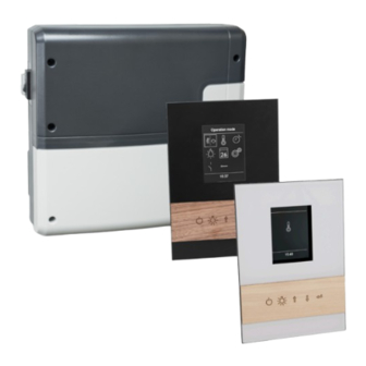
2.3 Identification The EmoStyle Hi control unit consists of a relay box, a control panel, a temperature sensor and the connecting cables, and is used to operate a sauna cabin. Additional modules/devices can be connected to the relay box for total control of a sauna cabin, for example, lighting, fan and additional sensors. - Page 10 Identification 2.5 Intended use In conjunction with a suitable sauna heater, the EmoStyle D and EmoTec H control units are inten- ded to be used only to heat sauna cabins. It is suitable for residentialand commercial sauna cabins. The relay box and control panel are intended only for mounting on the wall. The control unit is not suitable for outdoor use.
-
Page 11: Scope Of Delivery
Scope of delivery 3. Scope of delivery Check the delivery to ensure that all components were delivered and that the unit is in proper working order. Contact your distributor if components are missing or damaged. The unit must not be operated if components are missing or damaged. The following parts are included in the scope of delivery: A. - Page 12 Scope of delivery Accessories (optional) ► Description Item number Bench sensor, beige, with 5 m cable 94 9181 Humidity sensor, beige, with 5 m cable 94 9182 Coloured light control module SBM-FL75 94 5996 Coloured light control module SBM-FL150 94 6007 Sound module SBM-Sound BT 94 5921 Remote start module...
-
Page 13: Technical Data
Technical data 4. Technical data Voltage (power supply) 400 V 3 N ~ 50/60 Hz max. 10 kW resistive load, may be extended with a power Switching capacity extension box (PEB) Fuse 3 x 16 A Ambient temperatures -10° C to +35° C (main block) Ambient temperatures -10°... - Page 14 Technical data Control characteristic Digital two-point control Card reader Micro-SD card slot in control panel Min. 5 W Connection for fan* max.150 W (only fans without starting capacitor). Only use fans suitable for phase leading edge control! Min. 5 W (20 mA) resistive loads - max.
-
Page 15: Installation Main Relay Box
Relay box installation 5. Relay box installation This chapter describes how to install the relay box and the most important components. Cables with the appropriate cross section should be used for the heater, vaporizer (steam genera- tor) or an other heating system, as well the light, fan and other components. All electrical installations and all connecting lines that are installed inside a cabin must be suitable for a use in a sauna / IR cabin (IPx4 class) or in a steam room / hammam (IP 65). - Page 16 Relay box installation Site requirements ► Ambient temperature during operation -10°C to 35°C ƒ Relative air humidity during operation 30% to 75% ƒ Ambient air may not be corrosive or have high salt content ƒ Storage temperature -20°C to +60°C ƒ...
- Page 17 Relay box installation 5.1 Relay box The relay box may be installed only outside the cabin. Recommended installation locations are e.g. outer wall of the cabin, plant room in order to suit the local installation situation. If empty conduits for electrical installations are already present, this dictates the position of the relay box. Observe the following guidelines for the installation.
- Page 18 Relay box installation Installing the relay box ► Necessary steps: 1. Preparing the installation Determine a suitable location. ƒ Route the lines. ƒ 2. Remove the hosing cover Unscrew the 6 screws for both parts of the ƒ housing. Remove both halves of the cover. ƒ...
- Page 19 Relay box installation 4. Open the relay box conduits for the lines. 5. Insert supplied rubber grommets into the openings of the lower part of the housing. 6. Route the connecting cables through the openings. A. Mains cable, cables for heating, light etc. B.
- Page 20 ƒ Light sources with conventional transformers max. 60 VAor 75W in conjunction with the ƒ EOS transformer 946321. NOTICE Material damage by unsuitable lamps or installation place Lighting and the control panel could become damaged if nondimmable light sources are installed.
- Page 21 Relay box installation Requirement to a fan ► Minimal power 5 W ƒ Maximum power 150W ƒ Voltage 230 V 1N AC ƒ Suitable for installation in humid conditions (IP65) ƒ Only fans without starting capacitor ƒ 5.4 Potential free contact (PFC) The relay box features a potential free contact.
-
Page 22: Installation Control Panel
Control panel installation 6. Control panel installation The housing for control panel is available in two versions: for mounting in the wall or for mounting on the wall. Both versions are designed for a mounting location on the outer wall of the cabin. If empty conduits for electrical installations are already present, this dictates the position of the control panel. - Page 23 Control panel installation Extending the control panel‘s control line ► For longer connections, special RJ10/RJ14 connecting cables with lengths of 10 m, 25 m, 50 m and 100 m are available as an option. Alternately, the supplied (as standard) 5-m line can also be extended with an RJ12/RJ12 coupling and an RJ12/RJ12 extension cord.
- Page 24 Control panel installation Mounting the housing ► Das Bedienteil ist mit einem externen Spannungsregler ausgestattet, um die Platine des Bedien- teils nicht mit zusätzlicher Wärmeentwicklung zu belasten. Dieses Bauteil befindet sich einem se- paraten Metallgehäuse und wird mit einer Verbindungsleitung an das Bedienteil angeschlossen. Legen Sie zunächst den Ort für den Spannungsregler fest.
- Page 25 Control panel installation Detach the control panel ► NOTE: do not drop the control panel. The glass plate of the display cannot be replaced. Insert the disassembly tools into the slots on the right-hand edge of the control panel. Demontagewerkzeug nicht an den Ecken oder direkt an der Glasplatte ansetzen.
- Page 26 Control panel installation Pull the routed control cable and the cable to the voltage regulator through the opening in the housing. So that the control panel can be removed again without any problems, do not lay the cables too tightly. Insert the lower part into the prepared wall opening.
- Page 27 Control panel installation Move the clamps outwards as far as possible and tighten the screws clockwise. The housing must sit firmly in the wall opening. ƒ Install the voltage regulator outside the cabin. The cable is about 3 m long. It must not be routed tightly. ƒ...
- Page 28 Control panel installation Plug in the control panel ► Place the control panel directly in front of the lower part. Pay attention to the correct alignment. Carefully press the control panel evenly into the housing until it audibly clicks into place. The control panel must be firmly seated in the housing.
-
Page 29: Sensor Installation
Sensor installation 7. Sensor installation CAUTION Fire hazard from overheating Requirements that apply to installing the main sensor may exist for certain sauna heaters. Before installation, ensure that there are no heater-specific requirements that apply ƒ to installing the sensor. Temperature sensor requirements ►... - Page 30 Sensor installation The main sensor is installed in observance of the following distances from the cabin wall, depen- ding on the cabin size. < 2 x 2 m > 2 x 2 m 19 cm 35 cm Cabin smaller than 2 x2 m Cabin larger than 2 x2 m Installing the temperature sensor ►...
- Page 31 Sensor installation Determine a suitable location for the installation. The main sensor (heater sensor) must be installed on the cabin ceiling above the sauna heater. A second sensor (bench sensor) can be installed above the back bench. Drill a hole in the cabin ceiling for the cable. NOTICE: Do not pull at the plug when routing the control line(s).
-
Page 32: Bench Sensor Installation
Bench sensor installation 8. Bench sensor installation (optional) Bench sensor requirements ► The bench sensor is mounted on the ceiling above the back sauna bench across from the sauna heater. Installation configuration – bench sensor Bench sensor installation ► The installation and connection of the bench sensor is as of the main sensor. See chapter „Sensor“ in installation section. -
Page 33: Humidity Sensor Installation
Humidity sensor installation 9. Humidity sensor installation (optional) Humidity sensor requirements ► The humidity sensor (optional) is installed in the middle of the side wall facing away from the sau- na heater and door, at a height of approx. 150 cm. Mounting place for humidity sensor Installing the humidity sensor ►... -
Page 34: Electrical Installation
Electrical installation Electrical installation This chapter describes how to connect the relay box‘s circuit board lines. For information on setup of the control panel, see chapter Commissioning Recommended installation sequence ► Before commencing installation, ensure that the relay box, the control panel, and the temperature sensor are mounted. -
Page 35: X83; Connection Overview - Hi-Series
Electrical installation Connection overview ► weiß/white grün/green braun/brown... -
Page 36: X83; Main Board Layout - Hi-Series
Electrical installation Terminals ► T 2A T 0.8A M A I N S O V E N V A P. light S1 S1 N FL FN LL LN L1 L2 L3 N W V U N A. Fuse T 2A Potential free contact (PFC) B. -
Page 37: X83; Heater Sensor, Bench Sensor, Humidity Sensor
Electrical installation 10.2 Sensors The temperature/humidity in the sauna cabin is set via the control panel. The set values are che- cked by sensors and controlled by the relay box. The sensors are connected to the RJ10 sensor jacks using RJ10 plugs. Each sensor can be connected to any one of the three jacks. -
Page 38: X83; Connections, Terminals
Electrical installation 10.5 Circuit board connections T 2A T 0.8A A. Humidity sensor (optional, only H-series) B. Bench sensor (optional) C. Heater sensor (main sensor) with STB 10.6 Terminals All lines must be connected to the corresponding terminals. Heat-resistant cables must be used for the light, fan, and vaporiser connections. -
Page 39: X83; High Limiter, Light, Fan, Pfc, Connection Of The Sauna Heater And Vaporizer
ƒ If the installation uses multiple sauna heaters, multiple safety temperature limit- ƒ ers may be required. Observe the separate EOS instructions. 10.8 Light and fan The terminals light and fan must have only one line connection. A fan with 5 W to 150 W may be connected to the fan terminal. The fan may not have a starting capacitor. - Page 40 Electrical installation WARNING Fire hazard from overheating If the connection for the water bath (WB) and water shortage (WM) are swapped, the thermostat is jumpered. The water shortage cannot be detected. The vaporiser overheats. Do not swap the connections for the water bath (WB) and water shortage (WM). ƒ...
-
Page 41: X83; Heating Time Limitation
Electrical installation If installed properly, the vaporiser will switch on and off according to the humidity setting. If the Wb and Wm connections on the vaporiser are swapped, the vaporiser will not switch ƒ off and continue to run uninterrupted. If the line to Wm is disconnected, the Water shortage error message has to appear. -
Page 42: X83; Data Lines
Electrical installation 10.14 Connecting data line WARNING! Ensure that the relay box has no power. Open the housing. Removing the housing cover. ƒ Route the line through the openings ƒ at the base or on the back of the housing. The main relay box must be con- ƒ... -
Page 43: X83; Connecting The Consumer Lines
Electrical installation Recommended sequence: ► Connect the cabin lighting ƒ Connect the fan ƒ Connect the sauna heater ƒ Connect the vaporiser (if necessary) ƒ Connect external device to the PFC if such device is available. ƒ Connect the main connection ƒ... -
Page 44: X83; Closing The Housing
Electrical installation 10.16 Closing the relay box housing The following work must be completed before you close the housing: Connecting data lines ƒ Connecting and configuring consumers. ƒ Programming of the cabin address (chapter Multicabin-Installation). ƒ If the device is connected correctly and switched on, a green LED flashes on the main circuit board after a short start-up period. -
Page 45: Setup (Commissioning)
Setup Setup (commissioning / first switching) In order to commission the control unit, the cabin must be switched on at the control panel. If the display is blank, the relay box might be switched off. A unit switch is located on the left side of the relay box. Attention! Parts of the printed circuit board will still remain energized in the switched off con- dition! Risk of electric shock! Unit switch on relay box... -
Page 46: X83; Overview, Main Elements And Functions
All cabin settings are made at the control panel. All functions must be configured to commission the system. Add-on modules or accessories are detected after the unit is switched on again and their corre- sponding icons appear in the sub-menus. 09:12 Control panel EmoStyle Hi Display Icon buttons Key elements and functions ►... -
Page 47: X83; Initial Setup
Setup Selected icons are displayed inside a white frame. Once the selection is confirmed, the ƒ rame turns green and the display now shows the selected function. When a value is entered, a line appears under the active place value. Confirmed values are ƒ... -
Page 48: X83; Changing The Cabin Id (Address)
Setup 11.3 Changing the cabin address (ID) The main relay box has the factory default digital cabin address (ID) set to “1”. Under normal circumstances you do not need to change this address. If the main relay box or a optional module have been set to another address, they will not be detected by the control panel. -
Page 49: Manual Setting Of The Light Source
Manual setting of the lamp Manual setting of the lamp The control unit is factory set to inductive lighting load. Hence, resistive loads can also be con- trolled. If required, the light output can also be switched manually to capacitive loads. When using incandescent lamps, the lighting load must remain set to inductive load. - Page 50 Manual setting of the lamp Lichtlast auf ohmsche Last einstellen ► 1. If applicable, open the housing of the power unit. 2. Check whether the power unit is disconnected from the power supply. 3. Disconnect the light on the main board. 4.
-
Page 51: Operation
Betriebsart Betriebsart Temperatur Temperatur 20:51 20:51 20:51 20:51 Settings interface for EmoStyle Hi. Settings interface for EmoStyle Hi The symbol for dry or humid mode selection is shown as the (with disabled vaporizer). 1st option. -
Page 52: X83; Symbols (Main Menu)
Operation 13.1 Operation principle Press the button , in order to select a function (icon). Press shortly the ENTER button open this function. Press the buttons to change the value (changed value turns from white to green). Press the ENTER button to save (confirm) the setting and exit, the control panel will then return to the previous (upper) menu. -
Page 53: X83; Graphic User Interface, Checking Climate Condition
Operation 13.2 Graphic user interface (GUI) and the current climate conditions check Thanks to the modern graphic user interface you can quickly access all functions and make ne- cessary settings, as well as make a simple instant query for the current sauna climate condition. The symbols on the start screen may be displayed in different colours, in order to indicate the cur- rent operation status - e.g. -
Page 54: X83; Operation And Settings (Main Functions)
Operation NOTICE: Please pay attention that the shown values for the current temperature (humidity) are measured at the sensor location point. Because of the considerable differences in temperature in different parts of a sauna these values may vary from the values shown by the instruments moun- ted at the sauna wall. - Page 55 Operation confirm and exit. This setting can be also made during rH [%] active heating. Humidity (only EmoStyle H) Select and press the humidity symbol in the main menu. A submenu will open and show the last stored humidity value. Set the desired humidity with the UP/ T [°C] DOWN button.
- Page 56 Operation new setting and to exit the submenu. Please observe that the light dimming will only function if a dimmable transformer or a regular resistive load incandescent bulb has been connected. Make sure to observe the minimum and maximum power load for the connected lamps (see specifications or contact your dealer). Timer Timer Timer (switch-on time pre-selection)
- Page 57 Operation Now set the day, month and year for the desired switching. Then in the new window set the start time (hours and minutes). Then in the new window set the operation type (dry Finnish sauna or humid sauna). Then as the last step set the preferred temperature and humidity (only for humid mode).
- Page 58 Operation 4. to delete the program, set the start time (hour and minutes) to “--“ and shortly press the ENTER button twice to confirm and exit. 5. The display will return to the week overview. NOTICE: With an active week timer you will always see the next earliest switching time displayed flashing in the bottom right corner.
-
Page 59: X83; Symbols (Extended Settings)
Operation HOT - Zusatzfunktionen Mit dem Code 7020 kann mit Ablauf jeder HOT-Aufheizphase über den potentialfreien Ausgang (PFC) ein 3 sek. langer Impuls ausgegeben werden, um z.B. den Hinterwandaufguss „Aquadisp“ zu starten oder um einen Signalgeber, wie z.B. Gong, anzusteuern. Auf das Symbol >3 Sek. -
Page 60: X83; Operation And Settings (Extended Settings)
Operation Sleep mode Child lock Here you can set the interval, after which the Here you can lock the unit with own Pin-code. It control panel goes into sleep mode in order to will be still possible to switch off the heater and save power. - Page 61 This setting defines the period of time after which the control panel will enter the screensaver mode if no button has been operated. In this mode the display brightness will be reduced to the minimum and the display will show the current time (or EOS-Logo et al enlarged) floating across the screen. Press the button or press on the on/off button shortly in order to return to the start screen.
- Page 62 Operation confirm the first zero ( press ), then hold the button pressed for the second zero (first two zeros turn green, the cursor jumps to the third zero). After approx. 40 seconds all four zeros will turn white. Now confirm all four zeros with the ENTER button - upon exiting the unit will be unlocked.
- Page 63 Operation Press the UP/DOWN button to switch between two possible parameters. “Panel Vx.xx“ - ƒ shows the firmware in control panel, “Mod-LS Vx.xx“ - shows the firmware in the main relay unit (x stands for a number). Press on the ENTER button to close this submenu. Service intervals - allows to check the remaining time until the next pending servicing / maintenance of your sauna.
-
Page 64: Service Level Settings
Service & Setup level Service & Setup level Additional important settings and basic functions can be set up and adjusted in a separate area that is protected by a PIN code. In the main menu select the symbol and press the ENTER button for approx. 6 - 7 seconds until a pin code prompt window opens. -
Page 65: X83; Symbols
Service & Setup level 14.1 Symbol description Service / maintenance intervals Temperature adaptation Setting the intervals for service / maintenance. Setting for the temperature offset +/- °C. HOT-time Setting in minutes (5-20 min.) Fan speed settings. Only for dry Finnish operation. Refilling time HOT-auto interval time Switch-off time settings (only for EmoTec H) -
Page 66: X83; Settings
Service & Setup level 14.2 Settings Service intervals Allows to set the intervals for servicing and maintenance. Upon expiry the control panel will re- mind the user for a short time upon every switching about the pending servicing. The end user can check the remaining time to the next servicing in the extended settings menu. - Page 67 Service & Setup level sauna heater to the specific sauna cabin size and layout. ATTENTION! A smaller hysteresis value will lead to considerably increased number of relay swit- chings, which reduces the service life expectation of the control unit! The factory default setting is 5K.
- Page 68 Service & Setup level Please make sure to observe the maximal allowed temperatures as per norm EN 60335-2 part 53. HOT-time In this menu the duration of the HOT-function is set. During this time, the set-point temperature is increased to 115 °C to produce a short-term performance boost. Setting range: 5 to 20 minutes.
- Page 69 Service & Setup level Factory default setting: 0 (only manual deactivation of the ECO mode) ƒ NOTICE: by „0“ setting the ECO mode can be only deactivated manually, but will stop after 18 hours of heating. HOME (remote control via building management systems) The control unit supports the possibility of remote control via building management systems run- ning on KNX or Modbus communication protocols.
-
Page 70: X83; Potential Free Contact (Pfc)
Service & Setup level installation and operation manuals. Weitere Funktionen des PFC These functions can be set by entering the appropriate code, by going to the symbol in the main menu and press the ENTER button for approx. 6-7 seconds and then entering one of the codes from the „PFC codes“... - Page 71 Service & Setup level 7008 PFC closed, when sauna is switched on AND when ECO is active, otherwise open. Application: An external device shall be switched when ECO mode is active. 7009 PFC closes, when the sauna is switched on and opens after the sauna has been switched off or switched in after heating time.
-
Page 72: X83; Updating Firmware
FAT32 file system. You can obtain the update from EOS as follows: Memory card with firmware. ƒ ZIP file with the zipped update files as a download from the EOS homepage. ƒ NOTICE Equipment damage due to a faulty update The device can become unusable if the update is interrupted. - Page 73 Open the context menu (right mouse button) and select Format. The micro SD card must be formatted with the FAT32 file system. Preparing the update ► Download the most recent firmware from the EOS website. eos-sauna.com/service-support/ software Unzip the downloaded ZIP file and move it to the formatted memory card. Dismantling the front panel ►...
- Page 74 Service & Setup level Installing the update ► NOTICE Ensure that the power supply is not interrupted during the update process. Insert the memory card into the card slot on the PCB of the control panel. You must feel the card click into place. Switch the off switch on the relay box to I.
-
Page 75: Error Messages (Troubleshooting)
These are displayed in plain text, so that the error Fehlerbeschreibung identification and troubleshooting is much easier. In addition, the device also alternately displays the contact information to allow faster technical assistance. EOS Saunatechnik GmbH 35759 Driedorf Tel: +49277582-0 info@eos-sauna.de www.eos-sauna.de... - Page 76 ƒ the fault persists, contact the dealer or EOS service. If any other unidentified error messages appear, please contact EOS service. Make sure to supply the serial number, fault details and other relevant information. The model name, item number and serial number are printed on the type plate. The type plate is...
-
Page 77: Recycling
Electronic waste Electronic waste must be disposed of at the designated local collection point for electronic waste. Additional disposal note for commercial users: Further disposal instructions can be found under the link www.eos.sauna.de/recycling Service Address EOS Saunatechnik GmbH Tel: +49 (0)2775 82-514... -
Page 78: General Terms And Conditions Of Service
The manufacturers General Terms and Conditions of Business, The manufacturer shall assume liability in accordance with the which can be found at www.eos-sauna.com/agb, shall apply in currently applicable statutory regulations. The packaging for all addition to the foregoing terms and conditions of service.
Need help?
Do you have a question about the EmoStyle Hi and is the answer not in the manual?
Questions and answers