
Related Manuals for EOS InfraStyle


Summary of Contents for EOS InfraStyle
- Page 1 InfraStyle / InfraStyle i Control unit for infrared cabins Installation Instructions for retailers Made in Germany Druck-Nr.: 2902 5036 Stand: 25/19...
-
Page 2: Documentation
Read instructions Result of a step Table title Title of figure Revision history Date Version Description 23 April 2019 01.00 First version 25/2019 01.10 Installation dimensions for InfraStyle i changed. Installation Instructions - InfraStyle / InfraStyle i... -
Page 3: Table Of Contents
Circuit board assignment................53 5.2.1 Terminals ..................54 5.2.2 Emitter type – jumper JP1 and JP2.........54 5.2.3 Unit address – ADR DIP switch ..........55 5.2.4 Channels – DIP switches IR1 to IR3.........55 Connection diagram ...................57 InfraStyle / InfraStyle i - Installation Instructions... - Page 4 Switching hysteresis for the IR temperature...... 80 Defining the light source manually ............83 Heating period limiter ................85 Troubleshooting ..................87 7 General terms and conditions of service ..........88 8 Disposal ........................91 Installation Instructions - InfraStyle / InfraStyle i...
-
Page 5: General Safety Instructions
Caution Indicates a hazardous situation which, if not avoided, could result in minor or moderate injury. NOTICE Notice Indicates a hazardous situation which, if not avoided, will result in damage to the unit. InfraStyle / InfraStyle i - Installation Instructions... -
Page 6: Mounting And Electrical Installation
60335-2-53 may be used. Install a safety temperature limiter if needed. Observe the manufacturer's safety and installation instructions for infrared emitters and heating foils. Observe the cabin manufacturer’s safety and installation in- structions. Installation Instructions - InfraStyle / InfraStyle i... -
Page 7: Operator Instruction
Spending time in an infrared or sauna cabin can lead to serious health risks or even death for persons with health impairments. Persons with health impairments who spend time in a sauna must consult a doctor before entering an infrared or sauna cab- InfraStyle / InfraStyle i - Installation Instructions... - Page 8 Children and persons who have not received proper instruction must not clean or service the system. Installation Instructions - InfraStyle / InfraStyle i...
-
Page 9: Standards And Regulations
Electromagnetic compatibility – Requirements for household appliances, electric tools and similar apparatus – Part 1: Emission DIN EN 55014-2 Electromagnetic compatibility – Requirements for household appliances, electric tools and similar apparatus – Part 2: Immunity InfraStyle / InfraStyle i - Installation Instructions... -
Page 10: Identification
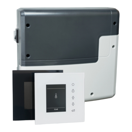
Identification Identification InfraStyle / InfraStyle i consist of a relay box and a control panel and are used to operate the infrared cabin. Unit information 2.1.1 Relay box The nameplate is attached to the underside of the base of the housing. -
Page 11: Infrastyle/Infrastyle I Control Panels
Identification 2.1.2 InfraStyle/InfraStyle i control panels Software version R. 3.50 or higher must be installed in the InfraStyle and InfraStyle i control panels. The nameplate is located on the inside of the front panel next to the circuit board. InfraStyle l schwarz Nussbaum... -
Page 12: Intended Use
The IR module is operated together with the relay box for the sauna cabin. InfraStyle / InfraStyle i is suitable for cabins used in private and commercial settings. The control panel is not suitable for outdoor use. -
Page 13: Description Of The Units
D 5-m connecting cable with RJ14/RJ10 modular plug for with RJ10 plug, housing, circuit board, 2 screws control panel 4x40 mm Relay box – scope of delivery Check the scope of delivery for completeness prior to installation. InfraStyle / InfraStyle i - Installation Instructions... - Page 14 The InfraStyle i control panel is supplied with one housing designed to be mounted in the wall. Installation Instructions - InfraStyle / InfraStyle i...
- Page 15 Infrared receiver for coloured light module and sound mod- 94.6810 SBM-GLT-MOD HOME Modbus module 94.7077 SBM-GLT-KNX HOME KNX module 94.7078 Modular distributor RJ12 for connecting cable for control 2001.5298 panel and sauna bus InfraStyle / InfraStyle i - Installation Instructions...
-
Page 16: Overview Of Relay Box
Position 0: Relay box is completely switched off. Parts of the circuit board are still energised. Position II: Cabin lighting is switched on, relay box is switched off. Position for maintenance and cleaning. Installation Instructions - InfraStyle / InfraStyle i... -
Page 17: Internal View Of Relay Box
Holes can be punched out at the predetermined points where needed. For more information on the circuit board, see 5.2 Circuit board assignment, 53 InfraStyle / InfraStyle i - Installation Instructions... -
Page 18: Control Panels
C Icons for program selection InfraStyle diagram The InfraStyle i control panel must only be mounted on the cabin's interior wall. In addition, a voltage regulator is mounted outside of the cabin. The InfraStyle control panel must only be mounted on the cabin’s exterior wall. -
Page 19: Technical Data
Housing Plastic Control panel dimensions (W x H x InfraStyle: 127 x 130 x 25 mm, mounting depth approx. 20 mm InfraStyle i: 142 x 202 x 42 mm, mounting depth approx. 37 Voltage regulator for InfraStyle i Aluminium housing, approx. 75 x 40 x 30 mm (L/W/H), cable length 3 m... -
Page 20: Installation
Routing data and power supply lines together can lead to elec- tronics malfunctions because, e.g. because the sensor will not be detected. Do not route sensor and sauna bus lines together with power supply lines. Route separate cable conduits. Installation Instructions - InfraStyle / InfraStyle i... - Page 21 Alternately, the supplied (as standard) 5-m line can also be extended with an RJ12/RJ12 coupling and an RJ12/RJ12 extension cord. The extensions and couplings are available as options. See Accessories (optional), 15 InfraStyle / InfraStyle i - Installation Instructions...
-
Page 22: Installation Work Inside The Cabin
The temperature sensor must be installed where expected temperatures are the highest. In an infrared cabin, this is typically at the centre of the cabin ceiling. Installation Instructions - InfraStyle / InfraStyle i... -
Page 23: Installing An Infrared Emitter
The total output may not exceed 3.5 kW. Connection Control Max. load Total output IR-1 Dimmable 1.5 kW Max. 3.5 kW IR-2 Dimmable 1.5 kW IR-3 Switchable 0.5 kW InfraStyle / InfraStyle i - Installation Instructions... -
Page 24: Installing The Temperature Sensor
Drill to drill a hole in the cabin ceiling Screwdriver Taught wire, as needed A Cabin ceiling C RJ10 plug for relay box B Temperature sensor on housing Installation diagram Installation Instructions - InfraStyle / InfraStyle i... - Page 25 C Brown (sensor bus) Connector pins for sensor bus Screw the sensor to the cabin ceiling and close the housing. Connecting the sensor line: IR relay box circuit board, 53 InfraStyle / InfraStyle i - Installation Instructions...
-
Page 26: Installing Cabin Lighting
Do not install lighting in the emitting range of an IR emitter. The lighting must conform to protection class IPX4 (splash- proof) and be resistant to ambient temperatures. Connect only dimmable light sources. Control line connection: Installation, 50 Installation Instructions - InfraStyle / InfraStyle i... -
Page 27: Relay Box
All lines should be routed before installing the relay box. Connections can be established later. Data lines must be routed and connected in such a way that they are not openly accessible. InfraStyle / InfraStyle i - Installation Instructions... - Page 28 Do not route sensor and sauna bus lines together with power supply lines. Route cable conduits separately. Measurements for installation 210 mm Back of relay box Installation diagram Installation Instructions - InfraStyle / InfraStyle i...
- Page 29 They are then passed into the housing from the rear. In both cases, the cabin insulation must be installed in such a way that the temperature in the area in which cables are routed cannot exceed 75°C. InfraStyle / InfraStyle i - Installation Instructions...
-
Page 30: Installing The Relay Box
Unscrew the 6 screws for both parts of the housing. Remove both halves of the cover. If you have already routed all data lines, you can set the DIP switches on the circuit board after you install the relay box. Installation Instructions - InfraStyle / InfraStyle i... - Page 31 B Lines with low voltage, e.g. sensor mains supply line, heat line, S-Bus (sauna bus) Either from below or from the rear. Insert supplied rubber grommets into the openings of the lower part of the housing. InfraStyle / InfraStyle i - Installation Instructions...
- Page 32 Route the connection cables through the openings. A Lines with mains voltage, e.g. B Lines with low voltage, e.g. sensor mains supply line, heat line, S-Bus (sauna bus) Either from below or from the rear. Installation Instructions - InfraStyle / InfraStyle i...
- Page 33 Once you have completed all installation work you can connect the consumers and plug in the lines. 5.4 Connecting data lines, 58 5.5 Connecting and configuring consumers, 60 5.6 Configuring the relay box, 63 InfraStyle / InfraStyle i - Installation Instructions...
-
Page 34: Control Panels
Installation Control panels The housing for the InfraStyle control panel is available in two models: for mounting in the wall or for mounting on the wall. Both models are designed for a mounting location on the outer wall of the cabin. - Page 35 Cabin insulation must be installed in such a way that the temperature in the area in which cables are routed cannot exceed 75°C. The InfraStyle i voltage regulator may not be exposed to elevated tempera- tures. It may not be mounted in the cabin wall.
- Page 36 Installation InfraStyle installation site The InfraStyle control panel is mounted outside of the cabin. The following distances are recommendations: ca. 340 mm 120 mm Dimensions at the mounting location Distance from the cabin door Min. 340 mm on the hinge side...
- Page 37 Installation InfraStyle i installation site The InfraStyle i control panel is mounted inside the cabin, however not near rising hot air or in the direct emitting range of an IR emitter. The cabin wall must be at least 37 mm thick.
-
Page 38: Mounting The Infrastyle
Mounting the housing on the wall, 42 Connecting the S-Bus, 43 Fixing the front panel, 44 InfraStyle with housing for mounting in the wall InfraStyle with housing for mounting on the wall Mounting diagrams... - Page 39 Route the control line from the relay box to the control panel. The smaller RJ10 plug on the connecting cable must be routed to the control panel. InfraStyle / InfraStyle i - Installation Instructions...
- Page 40 Observe the sticker on the housing (oben/up). When fixing the unit to the wall, ensure that the bottom of the unit is aligned properly. The side with the slot for the removal tool must be facing downwards. Installation Instructions - InfraStyle / InfraStyle i...
- Page 41 Wall thickness < 15 mm: Loosen the clips completely, rotate the clips and remount. c) Wall thickness > 30 mm: Remove the clips completely and tighten the housing with wooden screws. The housing must sit firmly in the wall cut-out. InfraStyle / InfraStyle i - Installation Instructions...
- Page 42 Allow the screw to protrude approx. 3 mm so you can hook in the housing. Hook the housing into the upper screw using the upper mounting hole. Route the control line from the relay box to the control panel. Installation Instructions - InfraStyle / InfraStyle i...
- Page 43 Insert the control line with the RJ10 plug into the circuit board. The control line's RJ10 plug is inserted into the circuit board on the control panel. The RJ14 plug is inserted into the relay box. InfraStyle / InfraStyle i - Installation Instructions...
- Page 44 The front panel must sit firmly on the housing. For commissioning information, see 6.2 Configuring during commissioning or after a reset, 68 Installation Instructions - InfraStyle / InfraStyle i...
-
Page 45: Mounting Infrastyle I
Installation 4.4.3 Mounting InfraStyle i The InfraStyle i control panel is equipped with an external voltage regula- tor to prevent additional heat generation at the control panel’s circuit board. This component is located in a separate metal housing and is con- nected to the control panel with a connecting cable. - Page 46 Installation InfraStyle i: Loosening the front panel NOTICE Do not drop the front panel. The display’s glass plate cannot be replaced. Insert the removal tools in the slots on the right side of the control panel. Do not apply the removal tool to the corners or directly to the glass plate.
- Page 47 After routing, pull the control line and the line to the voltage regulator through the opening in the housing. Do not pull the lines too taught so that you can easily remove the control panel at a later time. InfraStyle / InfraStyle i - Installation Instructions...
- Page 48 Mount the voltage regulator outside of the cabin. The cable is approx. 3 m long. It may not be taught. InfraStyle i: Inserting the S-Bus and voltage regulator line Insert the control line with the RJ10 plug into the circuit board.
- Page 49 Attach the white plug carefully and without pressure onto the corre- sponding jack on the circuit board. InfraStyle i: Fixing the front panel Place the front panel directly in front of the bottom piece. Ensure that it is aligned properly.
-
Page 50: Installation
Establish connection to the power supply. Switch on the relay box and control panel. Configure the control panel’s channels. Configure additional settings at the control panel, e.g. target tempera- ture for emitters. Installation Instructions - InfraStyle / InfraStyle i... -
Page 51: Sample Installation
Installation Sample installation In an installation, one or more than one IR modules with IR emitters can be connected to an InfraStyle relay box and be controlled by the InfraStyle control panel. Standard installation A standard installation has one single installed infrared relay box. The IR emitters, lights, temperature sensors and control panel are connected to this relay box. - Page 52 Installation Advanced installation A maximum of 2 infrared modules may be connected to the InfraStyle relay box in an advanced installation. IR-Emitter 1 IR-Emitter 4 IR-Emitter 7 IR-Emitter 2 IR-Emitter 5 IR-Emitter 8 IR-Emitter 3 IR-Emitter 6 IR-Emitter 9 230 V AC 50 Hz...
-
Page 53: Circuit Board Assignment
1.2 kW. In this case, the fuse at F2 (T4A H 250V) must be replaced by a T6.3 A H 250 V fuse. The power supply must be mounted outside of the cabin. InfraStyle / InfraStyle i - Installation Instructions... -
Page 54: Terminals
Emitters (R) are connected to IR-1. IR-2 is switched off. Connection IR-3 is configured for emitters at the factory. Connections IR-1 and IR-2 are switched off if no jumper is set. IR-3 remains switched on. Installation Instructions - InfraStyle / InfraStyle i... -
Page 55: Unit Address - Adr Dip Switch
IR-1 and IR-2, the DIP switches for the channel groups are set as follows. Channel IR1 to Example Example – channel Do NOT combine dimmable and switchable IR emitters in one channel group. InfraStyle / InfraStyle i - Installation Instructions... - Page 56 If you would like the IR emitter without an assignment to a channel group but assigned to the IR-3 output to switch on when the cabin is switched on, the DIP switches in IR3 must all be set to OFF. IR-3 starts with cabin Installation Instructions - InfraStyle / InfraStyle i...
-
Page 57: Connection Diagram
EN 60335-2-53 may be used. The power supply must be mounted separately and outside of the cabin. It may not be mounted in the relay box. InfraStyle / InfraStyle i - Installation Instructions... -
Page 58: Connecting Data Lines
B RJ10 plug for sensor line E Safety temperature limiter C Power supply connection F Jumper at safety temperature limiter terminal Plug the S-Bus line RJ10/RJ14 from the control panel into the free jack RJ14 (S-BUS). Installation Instructions - InfraStyle / InfraStyle i... - Page 59 By default, the safety temperature limiter terminal is jumpered at the relay box circuit board. A safety temperature limiter is not needed for an IR-only installation, since temperatures above 70°C cannot be reached by the IR emitters. InfraStyle / InfraStyle i - Installation Instructions...
-
Page 60: Connecting And Configuring Consumers
5.5 m in length. The lines must be connected as shown in the circuit dia- gram. You can connect multiple IR emitters to each of the terminals IR-1, IR-2 and IR-3. The IR emitter lines must all have the same cross-section. Installation Instructions - InfraStyle / InfraStyle i... - Page 61 Example – plug-in modules (optional) A Cabin lighting connection C IR emitter connection B Main power supply connection D Power supply connection InfraStyle / InfraStyle i - Installation Instructions...
- Page 62 Connect the power supply to the 24-V DC jack (D). Do not establish a connection to the power supply until you have set all switches. See 5.6 Configuring the relay box, 63. Installation Instructions - InfraStyle / InfraStyle i...
-
Page 63: Configuring The Relay Box
IR emitters and channel groups must be set. As a rule, the unit address for the relay box must not be changed. In installations with InfraStyle and InfraStyle i control panels, relay boxes are always assigned cabin address 1. - Page 64 Switch 2 = ON: Channel group B Switch 3 = ON: Channel group C You can assign the IR outputs to the same channel group, e.g. IR-1 and IR-3 to channel group A, IR-2 to channel group B. Installation Instructions - InfraStyle / InfraStyle i...
-
Page 65: Closing The Relay Box Housing
The power supply must be mounted separately and outside of the cabin. It may not be mounted in the relay box. Put the upper and lower cover halves in place. Screw in the 6 screws. InfraStyle / InfraStyle i - Installation Instructions... -
Page 66: Commissioning
Position 0: Relay box is completely switched off. Parts of the circuit board are still energised. Position II: Cabin lighting is switched on, relay box is switched off. Position for maintenance and cleaning. Installation Instructions - InfraStyle / InfraStyle i... -
Page 67: Operation Basics
When a value is entered, a line appears under the active place value. Confirmed values are displayed in green. InfraStyle / InfraStyle i - Installation Instructions... -
Page 68: Configuring During Commissioning Or After A Reset
Commercial use Special safety regulations apply to the commercial setting. See 1.3 Operator instruction, 7 This completes configuration of the IR cabin. The standby screen is displayed once configuration is complete. Installation Instructions - InfraStyle / InfraStyle i... -
Page 69: Configuring The Ir Control System
The control system cannot be configured until the IR emitters are installed and connected. The following describes only how to configure the IR emit- ters. Complete configuration and operation are described in the InfraStyle / InfraStyle i operating instructions. You should be familiar with the basic operating steps, e.g. navigating the menus and sub-menus and entering and saving settings. - Page 70 IR group 3 IR group 4 IR group 5 Each icon may be assigned only once. Installation example To make configuration easy to understand, the following example shows which switches must be set. Installation Instructions - InfraStyle / InfraStyle i...
- Page 71 IR emitters 6 and 7 are corner emitters. Both emitters have an output of 0.5 kW. They should switch off once the cabin temperature reaches 65°C. Emitter Connection Jumper Channel 1, 2, 3 IR-1 Emitter (R) 4, 5 IR-2 Foil (F) 6, 7 IR-3 InfraStyle / InfraStyle i - Installation Instructions...
-
Page 72: Configuring The Channel Groups
Settings °C 10:01 Enter code 5349 and confirm. Code Setting Code 5349 09:11 Increase or decrease the numbers and confirm by pressing Enter. Confirmed numbers appear green. Installation Instructions - InfraStyle / InfraStyle i... - Page 73 Commissioning : Select and confirm. IR setup °C 09:11 Select the channel and confirm. Assignment channel A A B C 09:15 InfraStyle / InfraStyle i - Installation Instructions...
- Page 74 Select the IR emitter icon and confirm. A: Back Middle A: Back Middle 10:55 10:55 You may assign each icon only once. Follow the same steps to configure the next channel group. Installation Instructions - InfraStyle / InfraStyle i...
-
Page 75: Adjusting The Ir Emitters
IR emitter, but rather switched off when the ambient tempera- ture reaches 70°C. In Foil operating mode, it is controlled via the ambient temperature sensor. Note that the intensity and temperature settings impact the duration of the heat-up phase. InfraStyle / InfraStyle i - Installation Instructions... -
Page 76: Ir Operating Mode
IR intensity. In this operating mode, only the intensity of the IR emitters can be set. Depending on the IR operating mode you select, you can now set the temperature and/or intensity. Installation Instructions - InfraStyle / InfraStyle i... -
Page 77: Ir Temperature
Set the temperature and confirm. Temperature Setting for operation IR mode 65°C 09:07 Confirm the set value. The value is saved and the display returns to the screen for operating mode selection. InfraStyle / InfraStyle i - Installation Instructions... -
Page 78: Ir Intensity
You can set the intensity only after you have defined the channel groups. See 6.4 Configuring the channel groups, 72 Setting the IR emitter intensity : Select and confirm. IR intensity °C °C 09:01 Select the channel and confirm. B: Back Middle 09:05 Installation Instructions - InfraStyle / InfraStyle i... - Page 79 The channel group emitters are immediately set to the new intensity. This means they are not set to the target temperature. Repeat steps 1 to 4 for the next channel. InfraStyle / InfraStyle i - Installation Instructions...
-
Page 80: Switching Hysteresis For The Ir Temperature
Setting the hysteresis : Select and press and hold until the code entry is displayed. Settings °C 10:01 CAUTION! Only trained personnel may change settings at the service level. Enter code 5349 and confirm. Installation Instructions - InfraStyle / InfraStyle i... - Page 81 Commissioning Code Setting Code 5349 09:11 Increase or decrease the numbers and confirm by pressing Enter. Confirmed numbers appear green. : Select and confirm. hysteresis °C 09:21 InfraStyle / InfraStyle i - Installation Instructions...
- Page 82 The setting range is between -10 K and +10 K. The value is set to 5 K by the factory. The value is saved and the display returns to the selection screen for advanced settings. Installation Instructions - InfraStyle / InfraStyle i...
-
Page 83: Defining The Light Source Manually
DANGER! Ensure that the relay box is disconnected from the power sup- ply. Disconnect the light source from the main circuit board. Reconnect the power supply and switch on the relay box again. InfraStyle / InfraStyle i - Installation Instructions... - Page 84 Code 8002: Capacitive load. Disconnect the relay box from the mains supply and reconnect the light source. Close the housing again. Reconnect the power supply and switch on the relay box again. Installation Instructions - InfraStyle / InfraStyle i...
-
Page 85: Heating Period Limiter
6 hours 8206 12 hours 8212 Unlimited 24 hours/7 days a 8224 week The number of hours applies to a continuous heating period. The heating automatically switches off once the heating period has ended. InfraStyle / InfraStyle i - Installation Instructions... - Page 86 Code 8206: 6 hours. Code 8212: 12 hours. Code 8224: 24 hours/7 days a week. The process of setting the heating period with the auto stop function is described in the operating instructions. Installation Instructions - InfraStyle / InfraStyle i...
-
Page 87: Troubleshooting
Too many add-on modules connected. Connect IR module with separate power supply. Bus connection plug not plugged in. Plug in plug. Bus cable damaged. Replace bus cable. Unit not detected. Set unit address for the module. InfraStyle / InfraStyle i - Installation Instructions... -
Page 88: General Terms And Conditions Of Service
The customer shall provide assistance free of charge to the manufacturer in rendering services. In the case of a warranty claim, the manufacturer shall provide replace- ment parts necessary for servicing free of charge. Installation Instructions - InfraStyle / InfraStyle i... - Page 89 Service visits made by third parties shall require a written order issued by our service department. The equipment in question shall be sent to our service department by the customer at the customer’s own expense. InfraStyle / InfraStyle i - Installation Instructions...
- Page 90 The manufacturer’s General Terms and Conditions of Business, in the ver- sion available at www.eos-sauna.com/agb, shall apply in addition to the foregoing terms and conditions of service. Installation Instructions - InfraStyle / InfraStyle i...
-
Page 91: Disposal
Do not dispose of the unit with household waste. Packaging InfraStyle / InfraStyle i packaging can be completely separated for disposal and recycled. The following materials are used in the packaging: Used paper, cardboard ... - Page 92 Store this address with the Installation Instructions in a safe place. Please always provide us with nameplate data, such as model, item num- ber and serial number so we can provide fast and efficient support. Date of sale Stamp/retailer signature: © EOS Saunatechnik GmbH - All rights reserved.
Need help?
Do you have a question about the InfraStyle and is the answer not in the manual?
Questions and answers