EOS EmoTec D Installation And Operating Instructions Manual
Control unit for sauna heaters
Hide thumbs
Also See for EmoTec D:
- Installation and operation manual (68 pages) ,
- Operation manual and user manual (47 pages) ,
- Installation and operation manual (50 pages)

Related Manuals for EOS EmoTec D


Summary of Contents for EOS EmoTec D
- Page 1 EmoTec D/H USA Control unit for sauna heaters Installation and Operating Instructions Made in Germany Druck-Nr.: 2902 5251 02/2023 Stand:...
-
Page 2: Documentation
Result of a step Table title Title of figure ≤ ≥ Less than or equal to, greater than or equal to Revision history Date Version Description 1 June 2022 01.00 First version EN-2 Installation and Operating Instructions - EmoTec D/H USA... -
Page 3: Table Of Contents
Relay box ....................EN-25 3.3.1 Requirements ................. EN-25 3.3.2 Installing the relay box............EN-27 Control panel ..................EN-30 3.4.1 Requirements ................. EN-30 3.4.2 Mounting the control panel..........EN-32 3.4.3 Mounting the fan ..............EN-39 EmoTec D/H USA - Installation and Operating Instructions EN-3... - Page 4 Circuit board assignment..............EN-45 EmoTec H USA – 6-9 kW, 208 V connection diagram ....EN-46 EmoTec D USA – 6-9 kW, 208 V connection diagram ....EN-47 EmoTec H USA – 6-9 kW, 240 V connection diagram ....EN-48 EmoTec D USA – 9 kW, 240 V connection diagram ....EN-49 EmoTec H USA –...
- Page 5 6.2.12 Operating data ..............EN-90 6.2.13 Display brightness ..............EN-94 6.2.14 Vacation home mode ............EN-94 Malfunction ..................... EN-97 7 General terms and conditions of service ........... EN-98 8 Disposal ......................EN-101 EmoTec D/H USA - Installation and Operating Instructions EN-5...
-
Page 6: General Safety Instructions
If the integrated battery in the control panel is not replaced cor- rectly, there is a risk of explosion which can lead to injury and fire The integrated battery may only be replaced by a qualified specialist. EN-6 Installation and Operating Instructions - EmoTec D/H USA... - Page 7 Similarly, excessive cold and extreme exposure to sunlight must be prevented. Protect the unit accordingly if there is an increased risk of me- chanical damage. EmoTec D/H USA - Installation and Operating Instructions EN-7...
-
Page 8: Operator Instruction
Spending time in a sauna cabin can lead to serious health risks or even death for persons with health impairments. Persons with health impairments who spend time in a sauna must consult a doctor before entering a sauna cabin. EN-8 Installation and Operating Instructions - EmoTec D/H USA... - Page 9 If the heating does not switch off automatically after a defined heating period, cabin use must be supervised at all times. Inspect the cabin before each use. EmoTec D/H USA - Installation and Operating Instructions EN-9...
- Page 10 Children and persons who have not received proper instruction must not clean or service the system. EN-10 Installation and Operating Instructions - EmoTec D/H USA...
-
Page 11: Safety Levels
For an overview of the standards that were observed during design and construction of the sauna heaters, please refer to the individual product’s technical data sheet that can be downloaded from www.eos-sauna.com. Local regulations also apply to the installation and operation of heating, sauna, and steam room systems. -
Page 12: Identification
Steamy hot air mode This documentation describes both models. Scope of delivery The following parts are included in the EmoTec D/H USA scope of delivery: A Relay box with front cover F Temperature sensor including 5 m B Cable glands M 16... -
Page 13: Nameplate
EOS-SAUNATECHNIK GmbH, Schneiderstriesch 1, 35759 Driedorf A Name E Protection class B Model F Country of origin C Item number G Manufacturer D Operating voltage and maximum H Manufacturing date switching output Serial number EmoTec D/H USA - Installation and Operating Instructions EN-13... -
Page 14: Technical Data
9 kW: 240 V, 2N: 2 x 50 A > 9–15 kW: 208V, 3N: 2 x 3 x 50 A Display TFT color display 55 x 74 mm / 2.2 x 2.9 inches (3.5” diagonal) EN-14 Installation and Operating Instructions - EmoTec D/H USA... - Page 15 Connections for heater: AWG 12 Memory card reader microSD memory card reader in control panel Connection for vapor- VAP1 and VAP2 with max. 1.5 kW each izer WM for water level sensor EmoTec D/H USA - Installation and Operating Instructions EN-15...
-
Page 16: Accessories (Optional
The heating period for the sauna heater is limited to one hour. Intended use EmoTec D/H USA is designed to operate sauna heaters in sauna cabins. The relay box and control panel are intended only for mounting on the wall. - Page 17 The unit is operated after technical or other modifications are made to the relay box. The unit is operated by children or persons with reduced mental capac- ity or by persons who have not been thoroughly instructed in its use. EmoTec D/H USA - Installation and Operating Instructions EN-17...
-
Page 18: Installation
65°C / 140°F. If the data lines are installed outside on the wall, they must be protected by a cable duct. EN-18 Installation and Operating Instructions - EmoTec D/H USA... - Page 19 ** Only use copper lines (cable type 2) that are approved for temperatures of min. 180 °C. *** The dimensions of cables and fuses may vary. Observe the information provided in the installation instructions for the corresponding sauna heater. EmoTec D/H USA - Installation and Operating Instructions EN-19...
-
Page 20: Installation Work Inside The Cabin
A Cabin fan C Temperature sensor with safety tem- B Light perature limiter Example – cabin The temperature sensor must be installed where expected temperatures are the highest. EN-20 Installation and Operating Instructions - EmoTec D/H USA... -
Page 21: Setting Up The Sauna Heater
Hardware + tools: Temperature sensor and connecting cables Drill used to drill a hole in the cabin ceiling Screwdriver Taut wire, as needed EmoTec D/H USA - Installation and Operating Instructions EN-21... - Page 22 35 cm 19 cm 0.6 ft 1.2 ft A Cabins < 2 x 2 m / 6.6 x 6.6 ft B Cabins > 2 x 2 m / 6.6 x 6.6 ft EN-22 Installation and Operating Instructions - EmoTec D/H USA...
- Page 23 E Brown (sensor bus) limiter Connector pins for safety temperature limiter and sensor bus Screw the sensor housing to the cabin ceiling and place the housing cov- er in position. EmoTec D/H USA - Installation and Operating Instructions EN-23...
-
Page 24: Bench Sensor
150 cm / 4.9 ft. Installation configuration – humidity sensor 3.2.5 Installing cabin lighting Lighting can be installed anywhere, however not near rising hot air. EN-24 Installation and Operating Instructions - EmoTec D/H USA... -
Page 25: Relay Box
This risk remains also after completion of the installation work. Do not install the relay box in enclosed cabinets or wood panel- ing. Mount the relay box in a dry environment only. EmoTec D/H USA - Installation and Operating Instructions EN-25... - Page 26 All lines should be routed before installing the relay box. Data lines must be routed and connected in such a way that they are not openly accessible. EN-26 Installation and Operating Instructions - EmoTec D/H USA...
-
Page 27: Installing The Relay Box
Inside back of relay box 3.3.2 Installing the relay box Preparing for installation Determine a suitable location for the installation. Route the lines. Loosen the 8 screws on the cover. Remove the cover. EmoTec D/H USA - Installation and Operating Instructions EN-27... - Page 28 D Conduits intended for heating circuit 2 (up to 15 kW) Insert supplied rubber grommets into the openings of the lower part of the housing. Installing the relay box Drill holes as required. EN-28 Installation and Operating Instructions - EmoTec D/H USA...
- Page 29 Once you have completed all installation work, you can connect the consumers and plug in the lines. 4.10 Safety temperature limiter, EN-52 4.12 Connecting the mains supply and units, EN-53 EmoTec D/H USA - Installation and Operating Instructions EN-29...
-
Page 30: Control Panel
A Inner wall of the cabin C Control line B Insulation D Outer wall of the cabin Guide for data and control line(s) EN-30 Installation and Operating Instructions - EmoTec D/H USA... - Page 31 The control panel is mounted outside of the cabin. The following distances are recommendations: ca. 340 mm / 13.4 " 120 mm / 4.72 " Dimensions at the mounting location EmoTec D/H USA - Installation and Operating Instructions EN-31...
-
Page 32: Mounting The Control Panel
Mounting the housing on the wall, EN-37 Connecting the S-Bus, EN-38 Fixing the front panel, EN-39 The control panel must only be mounted on the cabin’s exterior wall. Two options are available: EN-32 Installation and Operating Instructions - EmoTec D/H USA... - Page 33 Insert the removal tool in the slot at the base of the housing. If you are mounting the housing on the wall, loosen the front panel in the same way. EmoTec D/H USA - Installation and Operating Instructions EN-33...
- Page 34 Attach the taut wire only to the cable. Route the control line from the relay box to the control panel. The smaller RJ10 plug on the connecting cable must be routed to the control panel. EN-34 Installation and Operating Instructions - EmoTec D/H USA...
- Page 35 When fixing the unit to the wall, ensure that the bottom of the unit is aligned properly. The side with the slot for the removal tool must be facing downwards. EmoTec D/H USA - Installation and Operating Instructions EN-35...
- Page 36 Wall thickness 15 to 30 mm / 0.59 to 1.18 inches: Loosen the clips and turn 90° outward. Tighten the screws again. b) Wall thickness < 15 mm / 0.59 inches: Loosen the clips completely, rotate the clips and remount. EN-36 Installation and Operating Instructions - EmoTec D/H USA...
- Page 37 Allow the screw to protrude approx. 3 mm / 0.12 inches so you can hook in the housing. Hook the housing into the upper screw using the upper mounting hole. Route the control line from the relay box to the control panel. EmoTec D/H USA - Installation and Operating Instructions EN-37...
- Page 38 Insert the control line with the RJ10 plug into the circuit board. The control line’s RJ10 plug is inserted into the circuit board on the control panel. The RJ14 plug is inserted into the relay box. EN-38 Installation and Operating Instructions - EmoTec D/H USA...
-
Page 39: Mounting The Fan
The fan is not included in the scope of delivery. Observe the separate installation instructions for the fan. Fan requirements Minimal output 5 W Maximum output 100 W Voltage 120 V 1N ~ Suitable for use in sauna cabins EmoTec D/H USA - Installation and Operating Instructions EN-39... -
Page 40: Installation
Electrical installation must only be carried out by a qualified and licensed electrician. The unit must be connected to the power supply according to the circuit diagram and the terminal scheme. EN-40 Installation and Operating Instructions - EmoTec D/H USA... - Page 41 Connect the consumer lines to the relay box. Establish connection to the power supply. Switch on the relay box and control panel. Start the unit and apply the basic settings. EmoTec D/H USA - Installation and Operating Instructions EN-41...
-
Page 42: Installation Examples
A Fan E Sauna heater with safety tempera- B Cabin lighting ture limiter C Control panel F Vaporizer (optional) D Safety temperature limiter G Relay box Sample installation: 9 kW models EN-42 Installation and Operating Instructions - EmoTec D/H USA... - Page 43 A Fan E Sauna heater with safety tempera- B Cabin lighting ture limiter C Control panel F Vaporizer (optional) D Safety temperature limiter G Relay box Sample installation: 15 kW models EmoTec D/H USA - Installation and Operating Instructions EN-43...
-
Page 44: Internal View Of Relay Box
B 3 x mains supply F Heating circuit 2 (up to 15 kW) 3 x vaporizers G Heating circuit 1 (up to 9 kW) C Earth bar Example – 15 kW connections EN-44 Installation and Operating Instructions - EmoTec D/H USA... -
Page 45: Circuit Board Assignment
(EmoTec H* only) K Terminal block for heating circuit 2 (up to 15 kW) * Terminal WM does not apply to EmoTec D. See the connection diagrams below for more information on connections. EmoTec D/H USA - Installation and Operating Instructions... -
Page 46: Emotec H Usa - 6-9 Kw, 208 V Connection Diagram
EmoTec H USA – 6-9 kW, 208 V connection diagram Fuse, cable type 1, 2: see Connecting cables and fuses, EN-19. * The power rail must be able to accommodate a min. of 50 A. EN-46 Installation and Operating Instructions - EmoTec D/H USA... -
Page 47: Emotec D Usa - 6-9 Kw, 208 V Connection Diagram
Installation EmoTec D USA – 6-9 kW, 208 V connection diagram Fuse, cable type 1, 2: see Connecting cables and fuses, EN-19. * The power rail must be able to accommodate a min. of 50 A. EmoTec D/H USA - Installation and Operating Instructions... -
Page 48: Emotec H Usa - 6-9 Kw, 240 V Connection Diagram
EmoTec H USA – 6-9 kW, 240 V connection diagram Fuse, cable type 1, 2: see Connecting cables and fuses, EN-19. * The power rail must be able to accommodate a min. of 50 A. EN-48 Installation and Operating Instructions - EmoTec D/H USA... -
Page 49: Emotec D Usa - 9 Kw, 240 V Connection Diagram
Installation EmoTec D USA – 9 kW, 240 V connection diagram Fuse, cable type 1, 2: see Connecting cables and fuses, EN-19. * The power rail must be able to accommodate a min. of 50 A. EmoTec D/H USA - Installation and Operating Instructions... -
Page 50: Emotec H Usa - 10-15 Kw, 208 V Connection Diagram
EmoTec H USA – 10-15 kW, 208 V connection diagram Fuse, cable type 1, 2: see Connecting cables and fuses, EN-19. * The power rail must be able to accommodate a min. of 50 A. EN-50 Installation and Operating Instructions - EmoTec D/H USA... -
Page 51: Emotec D Usa - 10-15 Kw, 208 V Connection Diagram
Installation EmoTec D USA – 10–15 kW, 208 V connection diagram Fuse, cable type 1, 2: see Connecting cables and fuses, EN-19. * The power rail must be able to accommodate a min. of 50 A. EmoTec D/H USA - Installation and Operating Instructions... -
Page 52: Safety Temperature Limiter
In addition to the temperature sensor (heater sensor) you can also connect an optional bench sensor and an optional humidity sensor to the control system. Routing the lines Route the lines through the openings at the top of the housing. EN-52 Installation and Operating Instructions - EmoTec D/H USA... -
Page 53: Connecting The Mains Supply And Units
The mains supply and the various units (consumers) are connected on the main circuit board. A Mains connection (supply line) C Connection for fan B Vaporizer connection (option- D Cabin lighting al) and water shortage signal E Potential-free contact (optional) (optional) EmoTec D/H USA - Installation and Operating Instructions EN-53... -
Page 54: Closing The Relay Box Housing
Closing the relay box housing When you have connected all the required lines you can close the relay box: Remounting the housing cover Remount the cover. Screw in the 8 screws. EN-54 Installation and Operating Instructions - EmoTec D/H USA... -
Page 55: Setting Up The Vaporizer (Optional
Housing cover is in place Preparing the vaporizer Open the water supply at the shut-off valve. Start the vaporizer. Please observe the installation and operating instructions for the connected heater with vaporizer. EmoTec D/H USA - Installation and Operating Instructions EN-55... -
Page 56: Commissioning
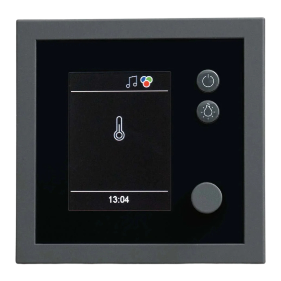
D Switch on/off (sauna heater) B Selected function E Switch cabin lighting on/off C Function icons F Jog dial Control panel The following controls are used to operate the unit: EN-56 Installation and Operating Instructions - EmoTec D/H USA... -
Page 57: Setup During Commissioning Or After A Reset
Settings that have not been saved are lost. Defining the basic settings Select a language and confirm. Set the time and confirm. Set the date and confirm. EmoTec D/H USA - Installation and Operating Instructions EN-57... -
Page 58: Service Settings
Defining the service Setting the cabin fan, interval, EN-60 EN-61 Refill period (if vaporizer is con- Post-heating time (if vaporizer is nected) connected) Setting the post-heating time, EN-63 EN-58 Installation and Operating Instructions - EmoTec D/H USA... -
Page 59: Opening Service Settings
CAUTION! Only trained personnel may change settings at the service level. Enter code 5349 and confirm. Increase or decrease the individual numbers and confirm. Confirmed numbers appear green. Select the desired icon and confirm. EmoTec D/H USA - Installation and Operating Instructions EN-59... -
Page 60: Service/Maintenance
When it is time for service again, a reminder with the saved contact data is displayed when the unit starts. For information about the amount of time remaining before service is required again, see Retrieving the next service date, EN-92. EN-60 Installation and Operating Instructions - EmoTec D/H USA... -
Page 61: Fan
Setting the cabin fan Open the service settings. See 5.2.1 Opening service settings, EN-59 : Select and confirm. Setting fan level 0 1 2 09:21 09:15 Set the level and confirm. EmoTec D/H USA - Installation and Operating Instructions EN-61... -
Page 62: Refill Period
Open the service settings. See 5.2.1 Opening service settings, EN-59 : Select and confirm. Refilling time Refilling time Setting Runtime 2 min 09:21 10:51 Set the time and confirm. EN-62 Installation and Operating Instructions - EmoTec D/H USA... -
Page 63: Post-Heating Time
Cabin heating continues for the set time and is then switched off. A value between 0 and 60°minutes can be set. Then specify the post-heating temperature. See Setting the post-heating temperature, EN-64 EmoTec D/H USA - Installation and Operating Instructions EN-63... -
Page 64: Post-Heating Temperature
Cabin heating continues at the set temperature and is then switched off. The value can be set to any number between 30°C and 90°C. Also specify the post-heating time. See Setting the post-heating time, EN-63 EN-64 Installation and Operating Instructions - EmoTec D/H USA... -
Page 65: Post-Cycle Period For Fan(S
Open the service settings. See 5.2.1 Opening service settings, EN-59 : Select and confirm. fan runtime fan running time with vaporiser 09:21 10:25 Select the operating mode and confirm. EmoTec D/H USA - Installation and Operating Instructions EN-65... - Page 66 The Bi-O operating mode has a preset of 30 min. The Finnish operating mode has a preset of 0 min. The time can be set between 0 and 60°minutes. The time is saved. EN-66 Installation and Operating Instructions - EmoTec D/H USA...
-
Page 67: Reset Function
09:16 09:16 Any customized settings that have been set will be lost. If you reset the settings, the control unit restarts and the cabin set- tings must be reset. EmoTec D/H USA - Installation and Operating Instructions EN-67... -
Page 68: Switch Contacts
The PFC is NO only if the sauna is switched on AND the cabin is heated. The PFC is NC when the sauna is switched off or during post-cycle. Application: The PFC is NO if the sauna is heated. EN-68 Installation and Operating Instructions - EmoTec D/H USA... - Page 69 The PFC is NC when the sauna is switched off or during post-cycle. Application: e.g. connection of an IR foil for faster heat sensing. EmoTec D/H USA - Installation and Operating Instructions EN-69...
- Page 70 6.2.5 Potential-free contact, EN-84. The potential-free contact is NO when the sauna heater is com- missioned. A unit is therefore switched on simultaneously when con- nected. The potential-free contact is deactivated. EN-70 Installation and Operating Instructions - EmoTec D/H USA...
- Page 71 Enter the desired code and confirm. The overview of codes can be found here: 5.2.9 Switch contacts, EN-68 Increase or decrease the individual numbers and confirm. Confirmed numbers appear green. EmoTec D/H USA - Installation and Operating Instructions EN-71...
-
Page 72: 5.2.10 Resetting The Temperature Display
Increase or decrease the individual numbers and confirm. Confirmed numbers appear green. The temperature is now displayed in Fahrenheit. Repeat the steps to change the setting back to Celsius. EN-72 Installation and Operating Instructions - EmoTec D/H USA... -
Page 73: Updating Firmware
SD card must be formatted with the FAT32 file system. You can obtain the update from EOS as follows: Card with firmware. ZIP file with the zipped update files as a download from the EOS home page. NOTICE Equipment damage due to a faulty update The device can become unusable if the update is interrupted. - Page 74 The SD card must be formatted with the FAT32 file system. Preparing the update Download the most recent firmware from the EOS website. eos-sauna.com/service-support/software Unzip the ZIP file you just downloaded and copy it to the formatted memory card.
- Page 75 See Repeating the update if unsuccessful, EN-76 Remove the memory card after the update. Place the front panel directly in front of the housing. Ensure that it is aligned properly. The S-Bus connection must face downward. EmoTec D/H USA - Installation and Operating Instructions EN-75...
- Page 76 Load the old software version onto the card. Perform the steps as described in Installing the update, EN-75. Repeat the update once the old software version has been restored. EN-76 Installation and Operating Instructions - EmoTec D/H USA...
-
Page 77: Operation
Press and hold for approx. 3 seconds until the heater is switched on. 10:51 The cabin is switched on with the pre-set parameters after the count- down. Press to switch off. EmoTec D/H USA - Installation and Operating Instructions EN-77... -
Page 78: Functions
O mode, EN-81 Settings Potential-free contact (if acti- vated) 6.2.5 Potential-free contact, EN-84 Back Language selection, Time, Defining the user interface Setting the time, EN-85 language, EN-85 EN-78 Installation and Operating Instructions - EmoTec D/H USA... - Page 79 (Bi-O) or not (Finnish). The operating mode is Finnish if no vaporizer is connected. Setting the operating mode : Select and confirm. Operation mode Operation mode Select with vaporiser (humid) 10:25 10:51 EmoTec D/H USA - Installation and Operating Instructions EN-79...
-
Page 80: Temperature
Temperature Temperature Setting for operation with vaporiser (humid) 60°C 10:51 10:51 Set the temperature and confirm. The value can be set to any number between 30°C and 70°C/86°F and 158°F. EN-80 Installation and Operating Instructions - EmoTec D/H USA... -
Page 81: Setting The Humidity For Bi-O Mode
The following icons are shown here: With humidity sensor: Without humidity sensor: Humidity in percent Humidity interval in humidity Setting the humidity, mode Setting the vaporizer level EN-83 (cyclic), EN-83 EmoTec D/H USA - Installation and Operating Instructions EN-81... - Page 82 Setting the humidity, EN-83 Setting the vaporizer level (cyclic), EN-83 EN-82 Installation and Operating Instructions - EmoTec D/H USA...
- Page 83 Humidity Setting vaporizer output 09:21 10:51 Set the vaporizer level and confirm. The vaporizer can be cycled for 300 seconds at a value between 1% and 100% within one interval. EmoTec D/H USA - Installation and Operating Instructions EN-83...
-
Page 84: Potential-Free Contact
10:51 09:25 Select the setting and confirm. Switch on potential-free contact (close). Switch off potential-free contact (open). 6.2.6 Language The user interface language can be switched in operation mode. EN-84 Installation and Operating Instructions - EmoTec D/H USA... -
Page 85: Time
: Select and confirm. Set the hours and minutes and confirm. Time Time Setting hour 08:21 09:21 09:01 A line appears under the active place value. The confirmed place value appears green. EmoTec D/H USA - Installation and Operating Instructions EN-85... -
Page 86: Date
Set the year, month and day and confirm your settings. Date Date Date Setting Setting year year 03.01.2019 03.01.2019 09:01 09:22 09:22 Once a setting is confirmed, the next place value is selected. EN-86 Installation and Operating Instructions - EmoTec D/H USA... -
Page 87: Screen Saver
Start time Screensaver Setting 08:21 09:01 Set the hours and minutes and confirm. The time is saved. The home screen with date and time is displayed as the screen saver. EmoTec D/H USA - Installation and Operating Instructions EN-87... -
Page 88: 6.2.10 Standby Mode
PIN. Entering the PIN for operational lock and activating it, EN-89 Deactivating the operational lock, EN-89 Resetting the PIN for operational lock, EN-90 EN-88 Installation and Operating Instructions - EmoTec D/H USA... - Page 89 You must enter the PIN to use any of the other functions. Deactivating the operational lock : Select and confirm. Enter the PIN and confirm. The display switches to the standby screen. All functions are available again. EmoTec D/H USA - Installation and Operating Instructions EN-89...
-
Page 90: Operating Data
Retrieving the firmware version and unit serial number, EN-91 Retrieving the next service date, EN-92 Retrieving contact data, EN-93 EN-90 Installation and Operating Instructions - EmoTec D/H USA... - Page 91 Use the jog dial to choose the display for the control panel or for the re- lay box. Firmware version Firmware version Serial 123456789 Serial 030123456 Panel M.-IR R 3.29 R 1.00 09:11 09:11 Examples for the displayed values EmoTec D/H USA - Installation and Operating Instructions EN-91...
- Page 92 Service/Maintenance 500 h 09:15 09:13 The amount of time remaining until the next service date is dis- played. The operation time is set to 500 hours by the factory. EN-92 Installation and Operating Instructions - EmoTec D/H USA...
- Page 93 09:01 : Select and confirm. Contact data Operation data EOS Saunatechnik GmbH Schneiderstriesch 1 35759 Driedorf Germany Tel: +49 (0)2775 82-514 Contact data Fax: +49 (0)2775 82-431 servicecenter@eos-sauna.de www.eos-sauna.de 09:15 09:15 EmoTec D/H USA - Installation and Operating Instructions EN-93...
-
Page 94: Display Brightness
PIN. Entering the PIN for holiday cottage mode and activating it, EN-95 Deactivating holiday cottage mode, EN-96 Resetting the PIN for holiday cottage mode, EN-96 EN-94 Installation and Operating Instructions - EmoTec D/H USA... - Page 95 The control unit cannot be used if the PIN is not known. Save the PIN in a safe place. Contact your retailer or EOS Service if you lose your PIN. If the holiday cottage mode is active, the language selection is displayed first after the system is switched on again by pressing the main switch.
- Page 96 09:16 Confirm all four white zeros. The zeros are displayed in green. The display switches to the standby screen. The lock is removed and all functions are available again. EN-96 Installation and Operating Instructions - EmoTec D/H USA...
-
Page 97: Malfunction
Battery in the control unit The battery may be ting defective. replaced only by a quali- fied specialist. Other errors Software error. Restart the control unit. Contact EOS Service. See Service address, EN-104. EmoTec D/H USA - Installation and Operating Instructions EN-97... -
Page 98: General Terms And Conditions Of Service
In the case of a warranty claim, the manufacturer shall provide spare parts necessary for servicing free of charge. IV. Service visit by the manufacturer Services rendered on site by an employee of the manufacturer must be agreed in advance. EN-98 Installation and Operating Instructions - EmoTec D/H USA... - Page 99 Only original spare parts may be used within the warranty period. Service visits made by third parties shall require a written order issued by our service department. EmoTec D/H USA - Installation and Operating Instructions EN-99...
- Page 100 Complaints in respect of our products shall be reported to the responsible distributor and shall be handled exclusively by said distributor. The manufacturer’s General Terms and Conditions of Business, in the ver- sion available at www.eos-sauna.com/agb, shall apply in addition to the foregoing terms and conditions of service. EN-100...
-
Page 101: Disposal
The following materials are used in the packaging: Used paper, cardboard Plastic foil Foam material Electronic waste Electronic waste must be disposed of at the designated local collection point for electronic waste. EmoTec D/H USA - Installation and Operating Instructions EN-101... - Page 102 EN-102 Installation and Operating Instructions - EmoTec D/H USA...
- Page 103 EmoTec D/H USA - Installation and Operating Instructions EN-103...
- Page 104 Store this address with the installation and operating instructions in a safe place. Please always provide us with nameplate data, such as model, item num- ber and serial number so we can provide fast and efficient support. Date of sale Stamp/retailer signature: © EOS Saunatechnik GmbH - All rights reserved.
Need help?
Do you have a question about the EmoTec D and is the answer not in the manual?
Questions and answers