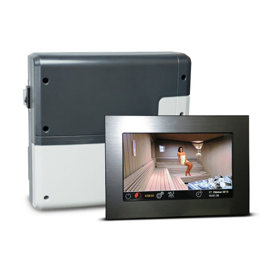
EOS EmoTouch II + Installation And Operation Instruction Manual
Touchscreen sauna control unit
Hide thumbs
Also See for EmoTouch II +:
- Installation and operating manual (40 pages) ,
- User manual and operating manual (30 pages)

Related Manuals for EOS EmoTouch II +


Summary of Contents for EOS EmoTouch II +
- Page 1 I N N O V A T I V E S A U N A T E C H N O L O G Y EmoTouch II + Touchscreen sauna control unit Installation and operation instruction Made in Germany Print no. 29344770 en / 36.16 Technical changes reserved...
-
Page 2: Table Of Contents
English Contents Scope of delivery ..............................4 Accessories ................................4 Technical data ................................5 General information about sauna bathing ....................6 General safety precautions ..........................7 Mechanical installation ............................9 Relay box ...............................9-10 Control panel (recessed installation) ......................11 Temperature sensor installation .......................14 Electrical connections ............................16 Connection of the sauna heater .......................16 Connection of the sauna lighting ......................17... -
Page 4: Scope Of Delivery
Scope of delivery (changes are reserved) Main electronic unit (with two-part front cover) Control panel with touchscreen display Housing base for ush-mounted installation of the control panel, with mounting brackets De-installation tool (for control panel) Temperature sensor: a) housing, b) sensor board, c) overheat protection fuse, d) 2 mounting screws 4 x 40 mm, e) connection cable 5 m with RJ10 plug, f ) 2-core white cable for overhea- ting protection fuse 5 m Connection cable 5 m (main unit - touchscreen display) with RJ14 / RJ10 plugs... -
Page 5: Technical Data
Technical data Voltage (power supply): 400 V 3 N AC 50 Hz Switching capacity: max. 9 kW resistive load, may be extended with a power extension unit (LSG) Heating time limit: 6 h / 12 h / unlimited Housing: plastic, shatter-resistant Display: 7“... -
Page 6: General Information About Sauna Bathing
Dear customer General information You have purchased a high-quality technical Please check whether the unit has arrived in per- device with which you will have years of sauna fect condition. Any transport damages should be fun. This sauna control unit was designed and immediately reported to the freight forwarder inspected according to the current European delivering the goods or you should contact the... -
Page 7: General Safety Precautions
General safety precautions ature setting. The temperature can be held within operating parameters and This device can be used by children aged • a minimal temperature gradient inside 8 upwards and by persons with physical, the bench area of the sauna cabin can be sensory, or mental disabilities, or who achieved only if unit is assembled correct- have inadequate experience and knowl-... - Page 8 When designing the cabin ensure that the external exposed glass surfaces only reach a maximum temperature of 76°C. If necessary, protective features need to be tted. Attention! Dear customer, according to the valid regulations, the electrical connection of the sauna heater and the control box has to be carried out through the specialist of an authorized electric shop...
-
Page 9: Mechanical Installation
Installation of the main relay box The main electronic unit (relay box) may be installed only outside sauna (steam room). The recom- mended places of installation are the outer wall or a plant room (technical room). The installation on the roof is also possible. If empty ducts for connection cable are already available, then they usually predetermine the installation position. - Page 10 Hang the housing on the central upper screw. Make sure that this screw stands out ap- prox. 3 mm from the wall surface. If the connection cables shall be connected from the rear, knock out the corresponding openings in the housing and insert the supplied cable glands (rubber cable holders) into these openings.
-
Page 11: Relay Box
Control panel Cable connection Draw the connection cable from the relay box Installation place to the control panel. The control panel may only be mounted out- The connection cable may be laid only be- side the sauna cabin. If ductwork is already tween the outer sauna wall and insulation layer provided for electrical installations then the to prevent overheating (Fig. - Page 12 Flush-mounted installation Wandausschnitt Wall aperture: Breite 188 mm Höhe 127 mm Width 188 mm Tiefe mind. 35 mm Height 127 mm Depth min. 35 mm all sizes in mm alle Maße in mm Notice: Pay attention to the correct ori- entation of the housing base, the opening for connecting cable should be at the bottom side as...
- Page 13 Installation of the upper part (control panel with display) Place the control panel directly in front of the housing base and pay attention to the correct ori- entation - the cable connector shall be at the bottom and the SD card slot at the top. Plug in the connection cable with RJ10 plug which you pulled through the housing base.
-
Page 14: Temperature Sensor Installation
Connection of sensor cables You should not install sensor and power supply lines together, or lead them through the same feedthrough. This can lead to interferences in the electronics, such as “ uttering” in the relays. Con- nect the cable shielding (if present) to ground in the control unit. Please observe that the following dimensions relate to the values stipulated during the unit in- spection acc. - Page 15 Lead the sensor cable (red) and the limiter cable (white) through the drilled hole and connect both cables to the main relay box as advised on pages 18-19. Connect the sensor cable to the sensor board according to g. 13. Make sure the connections are correct.
-
Page 16: Electrical Connections
Electrical connection Sauna heater connection The electrical connections may only be car- ried out by a certi ed electrician in compli- ance with the guidelines of the local power Install the sauna heater and the vaporizer (if supply company and applicable legal regu- available) inside the sauna cabin in front of the lations (e.g. -
Page 17: Connection Of The Sauna Lighting
Sauna lamp connection Heating time limitation The maximal heating time may be limited with the jumper #5 on the main board of the relay The sauna lamp must have the protection box. The limitation may be set to 6 hours, 12 class of at least IPx4 and should be resistant to hours or to unlimited. -
Page 18: Installation Diagram And Terminal Block Overview
Connection diagram EmoTouch II+ Feuchtefühler Steckeranschluß Fühler humidity sensor Sensor plug connector Bankfühler/2nd Sensor Ofenfühler/Sensor reserviert Leistungsteil Sensorbus Main unit (relay box) Relais box Силовой блок Saunabus light S1 S1 N L1 L2 L3 N W V U N L N L N Leuchte/light Lüfter/fan Bedienteil Control panel... -
Page 19: Temperature Sensor
Temperature sensor ATTENTION! Feuchtefühler humidity sensor Bankfühler If a sensor is plugged into the sauna bus 2nd Sensor Ofenfühler reserviert Sensor (RJ14 connector), the sensor and the main board may be irreparably damaged! Sensorbus RJ 10 The sensor cable with RJ10 plugs shall be con- nected to one of three sensor bus RJ10 jacks on Saunabus RJ 14... -
Page 20: Connection Scheme Overview
Fig. 19 shows standard vaporizer connection from (in humid operation (EOS models). EOS control units will detect wa- mode) to indicate humidity control as per rel- ter shortage if there is zero potential at the Wm ative air humidity. The humidity sensor will be terminal of the control unit. -
Page 21: Installation And Connection Of The 2Nd Temperature Sensor
Installation of the option- If the 2nd sensor is faulty the temperature will be controlled via the main sensor over the al 2 sensor heater. After the fault is recti ed the 2nd sensor will be automatically detected and con gured upon Place of installation: The 2nd sensor (bench the new start of the control unit. -
Page 22: Setup (Commissioning / Rst Switching)
Basic Setup (commissioning / rst switching) Using the control unit for the first time or after a reset The EmoTouch control unit provides quick and intuitive basic setup in four steps after the rst switching (commissioning of the unit) or after the system reset. Step 1 - set language Sprache Select the required language for the... - Page 23 - dry sauna heater without vaporizer (disabled vaporizer) - Bi-O sauna heaters with vaporizer. The basic setup is now complete and the control unit will switch to the standby mode. Further special settings and custom con guration of the control unit may be carried out in the service &...
-
Page 24: Operation
Operation Control panel - graphic user interface (GUI) Digital sand timer Light Climate Colour light check (optional) Vaporizer On/O Touch the symbol shortly to switch, touch >3 sec to make settings Temperature Temperature To make settings touch To make settings touch the heater >3 sec the heater >3 sec 15. -
Page 25: Operation Principle And Symbols
Operation principle with a touch screen GUI On the GUI (sauna cabin image) you can switch the functions by touching shortly the correspond- ing objects (e.g. lamp). By touching these objects >3 sec you can make settings (adjustments). The symbols in the lower black strip (except for “settings”) should be touched for >3 sec for safety reasons. -
Page 26: Symbol Description (Extended Settings)
Symbol description - extended settings „Extended settings“ sub-menu provides a range of additional functions, which normally need to be set only once or quite seldom. Touch the symbol shortly to enter this sub-menu. Language Time Here you can select one of 18 languages Here you can set the time of day. -
Page 27: Graphic User Interface / Monitoring Of Climate Conditions
Graphic user interface GUI and climate conditions check Thanks to the modern GUI you can quickly access all functions and make necessary settings, as well as make a simple instant query for the current sauna climate condition. The symbols on the start screen may be displayed in di erent colours, in order to indicate the current operation status - e.g. -
Page 28: Operation And Settings (Main Functions)
Operation and program settings Sauna on / o Touch the symbol for 3 sec. The sauna heater will switch on and the display will show the ac- tive heating (see page 29). The light will switch on automatically as well. To switch the sauna o , touch shortly the symbol again. - Page 29 Light on / o Touch shortly the image of the lamp on the display to switch the light on or o . Display indication: - light o , - light on. How to dim the cabin light You can quickly dim the cabin light (0-100%). Light Press the lamp image on the display for >3 sec.
- Page 30 Timer The timer function allows you to have your sauna switched on automatically with the desired cli- mate condition at some time in the future. You have two possible options: - single event (single time switching, not recurrent) Timer - week timer (regular, recurrent switching on the given day of the week, e.g.
- Page 31 1. Set the required start time (hours and minutes) - e.g. 9:30. 2. Set the required heating time (hours and minutes) - e.g. 3:30. 3. Set the required operation type - dry Finnish sauna or humid sauna (Bi-O heaters only) 4.
-
Page 32: Extended Settings
Extended settings Settings Touch the symbol on the start screen to enter the sub-menu for extended settings. 01. January 2014 15:20:35 The sub-menu „Extended settings“ allows you to make additional settings, which normally need to be set only once or quite seldom. Touch the symbol on the start screen to enter the sub-menu for extended settings. - Page 33 Child lock / Operation lock You can lock the control panel with the individual 4-digit pin code in order to prevent the unau- thorized access. In order to lock the display go to the settings Set Code menu, select the symbol and touch it again shortly to enter the settings.
- Page 34 Operation data Here you can check the important information concerning your control unit (sauna) operation. Firmware - allows to check the currently installed rmware version. Use “+” / “-” to switch between two possible parameters. „Panel Vx.xx“ - shows the rmware in the control panel, „Mod-LS Vx.xx“...
-
Page 35: Firmware Update
Potential-free contact With the potential-free contact (output) you can switch an additional external device on or o . This might be for instance an additional light circuit, music or some other feature. This function has to be enabled in the basis setup and the external device has to be properly connected and con gured. -
Page 36: Service Level (Setup And Settings)
Service and Setup Settings The EmoTouch II+ provides an extensive set of features and tools for the setup and tuning of sauna equipment. This setup menu is protected with a PIN code and should not be accessible to the end users. Hint: a short version of the operation manual without setup and installation is included with every control unit. - Page 37 Symbol overview Service intervals Potential-free contact Settings of intervals for servicing & maintenance. Enables or disables the potential-free contact switching function. Temperature adaptation Setting for the temperature o set +/- °C. Setting of the ventilation fan speed. Re lling time Back Grace time to re ll the vaporizer after water Exits and returns to the main menu.
- Page 38 Settings Service intervals Setting of the intervals for servicing and maintenance. Upon expiry the control panel will remind the user about the pending servicing for a short time upon every switching. The end user can check the remaining time to the next servicing in the extended settings menu. This function allows as well to keep track of the total operation time of the sauna.
- Page 39 Attention! The smaller hysteresis value will lead to considerably increased number of relay switch- ings, which reduces the service life expectation of the control unit! The factory default setting is 5K. Make sure to adjust this value with care! Basic Setup Here you can repeat the essential setup steps - selection between the private and commercial sauna use type, con guration of the safety system availability (for EU located saunas) and the se- lection of the connected heater type (dry sauna heater or Bi-O heater with vaporizer).
-
Page 40: Troubleshooting
Check cable connections and restart the control unit; if the fault persists, contact the dealer or EOS service If any other unidenti ed error messages appear, please contact EOS service. Make sure to supply the serial number, fault details and other relevant information. -
Page 41: Main Switch (Switch-O )
The device „Switch-o “ switch You will nd the rocker switch on the left side of the main relay box. You can completely dis- connect the control unit from the mains using this switch. Attention! Parts of the printed cir- cuit board will still remain energized in the switched o condition! Risk of electric shock! Device’s main switch... -
Page 42: Recycling
Service Address: EOS Saunatechnik GmbH Schneiderstriesch 1 35759 Driedorf, Germany Tel: +49 (0)2775 82-514 Fax: +49 (0)2775 82-431 servicecenter@eos-sauna.de www.eos-sauna.de Equipment commissioning date: Please keep this address in a safe place togeth- er with the installation guide. Stamp and signature of the authorized elec-... -
Page 43: General Terms And Conditions Of Service
General Terms and Conditions of Service shipments via parcel post. The manufacturer shall accept no liability for damage incurred as a result of improper I. Scope packaging in an individual shipment. Unless otherwise agreed in writing in a speci c case, the- VI.
Need help?
Do you have a question about the EmoTouch II + and is the answer not in the manual?
Questions and answers