
Related Manuals for EOS EmoTec H CAN


Summary of Contents for EOS EmoTec H CAN
- Page 1 EmoTec D/H CAN Control unit for sauna heaters Installation and Operating Instructions Made in Germany Druck-Nr.: 2902 5252 Stand: 08/2024...
-
Page 2: Documentation
Documentation Documentation Manufacturer EOS Saunatechnik GmbH Schneiderstriesch 1 35759 Driedorf, Germany Tel. +49 2775 82-514 +49 2775 82-431 Email servicecenter@eos-sauna.com www.eos-sauna.com Original installation instructions DE Copyright for these installation instructions remains with EOS Saunatechnik GmbH. The copying and distribution of this document, as well as the use and com- munication of its contents without express authorization, are not permit- ted. -
Page 3: Table Of Contents
Contents Documentation ....................EN-2 1 General safety instructions ................EN-6 Mounting and electrical installation ..........EN-6 Operator instruction................EN-8 Safety levels..................... EN-11 Standards and regulations..............EN-11 2 Identification....................EN-12 Scope of delivery ................... EN-12 Nameplate ....................EN-13 Technical data..................EN-14 Accessories (optional)................EN-16 Heating period limitation..............EN-16 Intended use ................... - Page 4 Installation examples................EN-43 Internal view of relay box..............EN-45 Circuit board assignment..............EN-46 EmoTec H CAN – 6–9 kW, 208 V connection diagram....EN-47 EmoTec D CAN – 6–9 kW, 208 V connection diagram....EN-48 EmoTec H CAN – 6–9 kW, 240 V connection diagram....EN-49 EmoTec D CAN –...
- Page 5 6 Operation......................EN-82 Switching on and off ................EN-82 Functions....................EN-83 6.2.1 Overview .................. EN-83 6.2.2 Operating mode ..............EN-84 6.2.3 Temperature ................EN-85 6.2.4 Setting the humidity for Bi-O mode....... EN-86 6.2.5 Potential-free contact............EN-89 6.2.6 Language ................EN-89 6.2.7 Time ...................
-
Page 6: General Safety Instructions
General safety instructions General safety instructions Mounting and electrical installation The installation instructions are intended for qualified per- sonnel familiar with the laws and regulations applicable to electrical installations at the installation site. Observe the fol- lowing general safety instructions during mounting, configu- ration and commissioning of the product. - Page 7 General safety instructions Fire hazard from overheating Insufficient ventilation can lead to device overheating and fire. Do not install control panels, relay boxes and modules in en- closed cabinets or wood paneling. Observe the sauna heater manufacturer’s safety and installa- tion instructions.
-
Page 8: Operator Instruction
General safety instructions Operator instruction The operator of the sauna cabin must be instructed in the general safety instructions during commissioning. The operator must be given a copy of the operating instructions. The operator must make the end user aware of safety instructions that are relevant to the end user. - Page 9 General safety instructions Equipment damage due to overuse Excessive humidity in commercial sauna cabins can lead to prop- erty damage. If the sauna cabin is used commercially, the heating time must be set so that it switches off automatically after a specific period of time.
- Page 10 General safety instructions Operation by children or persons with reduced mental capacity Children and persons with reduced physical, mental or sensory abilities must be supervised to ensure that they do not play with the unit. Children under 8 years of age should not operate the sauna cabin.
-
Page 11: Safety Levels
For an overview of the standards that were observed during design and construction of the sauna heaters, please refer to the individual product’s technical data sheet that can be downloaded from www.eos-sauna.com. Local regulations also apply to the installation and operation of heating, sauna, and steam room systems. -
Page 12: Identification
Identification Identification EmoTec D/H CAN can be operated in the following models: Finnish sauna mode Steamy hot air mode This documentation describes both models. Scope of delivery The following parts are included in the EmoTec D/H CAN scope of delivery: A Relay box with front cover G Housing for mounting on the wall (figure shows 10–15 kW model) -
Page 13: Nameplate
The nameplate is affixed on the right side near the switch. Sauna control unit Sauna control unit CONFORMS TO CONFORMS TO UL STD 60730-1 UL STD 60730-1 Type EOS EmoTec H CAN Type EOS EmoTec D CAN 60730-2-9 60730-2-9 CONFORMS TO CONFORMS TO Art.-Nr. 94 7786 00 Art.-Nr. -
Page 14: Technical Data
Software version R. 4.00 or higher must be installed in the control panel. The nameplate is located on the inside of the front panel next to the circuit board. EOS EmoTec H CAN EOS EmoTec D CAN 94 7770 00 S-No. - Page 15 Identification Max. 9 kW resistive load with one relay circuit board Switching output Max. 15 kW resistive load with two relay circuit boards 9 kW: 208 V, 3N: 3 x 50 A Fuses 9 kW: 240 V, 2N: 2 x 50 A >...
-
Page 16: Accessories (Optional
Identification Connections on main circuit board: AWG 14 Pipe cross-sections Relay supply line: AWG 10 Connections for heater: AWG 12 microSD memory card reader in control panel Memory card reader VAP1 and VAP2 with max. 1.5 kW each Connection for WM for water level sensor vaporiser Accessories (optional) -
Page 17: Intended Use
Identification Intended use EmoTec D/H CAN is designed to operate sauna heaters in sauna cabins. The relay box and control panel are intended only for mounting on the wall. EmoTec D/H CAN is suitable for cabins used in private and commercial set- tings. -
Page 18: Installation
Installation Installation Routing the lines All lines should be routed before installing the control unit. The connec- tions can be plugged in after installation, since the control unit’s front panel can be removed. NOTICE Electronics malfunctions Routing data and power supply lines together can lead to elec- tronics malfunctions because, e.g., the sensor will not be detected. - Page 19 Installation Connecting cables and fuses Connecting Connecting Heater out- Connection cable control cable Fuse voltage system * Heater ** 6.0 kW 208 V AWG 10 AWG 12 25 A 7.5 kW 208 V AWG 10 AWG 12 30 A 9.0 kW 208 V AWG 8 AWG 12...
-
Page 20: Installation Work Inside The Cabin
Installation Installation work inside the cabin At minimum, the cabin lighting and a temperature sensor must be installed inside the cabin. A Cabin fan C Temperature sensor with safety tem- B Light perature limiter Example – cabin The temperature sensor must be installed where expected temperatures are the highest. - Page 21 Installation Hardware + tools: Temperature sensor and connecting cables Drill used to drill a hole in the cabin ceiling Screwdriver Taut wire, as needed A Cabin ceiling C RJ10 plug for relay box B Temperature sensor housing ...
- Page 22 Installation 35 cm 19 cm 13.8 inch 7.5 inch A Cabins < 2 x 2 m / 6.6 x 6.6 ft B Cabins > 2x2 m / 6.6 x 6.6 ft: 20 cm inch Installation configuration above the heater Drill a hole in the cabin ceiling for the cable.
-
Page 23: Humidity Sensor
Installation Open the temperature sensor’s housing and connect the cable. A Terminal 1 for safety temperature C White (sensor bus) limiter D Green (sensor bus) B Terminal 2 for safety temperature E Brown (sensor bus) limiter Connector pins for safety temperature limiter and sensor bus Attach the sensor with screws to the cabin ceiling and place the housing cover in position. -
Page 24: Installing Cabin Lighting
Installation 3.2.3 Installing cabin lighting Lighting can be installed anywhere, however not near rising hot air. Cabin lighting is not included in the scope of delivery. Observe the sepa- rate installation instructions for lighting. Light source requirements: Minimal output 5 W ... -
Page 25: Requirements
Installation 3.3.1 Requirements WARNING Risk to life and limb and risk of fire Risk to life and limb from electric shock and fire in the event of im- proper or faulty electrical connection. This risk remains also after completion of the installation work. ... - Page 26 Installation If empty conduits for electrical installations are already present, this dic- tates the position of the relay box. All lines should be routed before installing the relay box. Data lines must be routed and connected in such a way that they are not openly accessible. Measurements for installation 445 mm / 18 inch ...
-
Page 27: Installing The Relay Box
Installation 3.3.2 Installing the relay box Drill holes as required. Insert anchors into the drill holes if necessary. Loosen the 6 screws on the cover. Remove the cover. EmoTec D/H CAN - Installation and Operating Instructions EN-27... - Page 28 Installation Insert the cable glands into the openings and tighten with the nut. A Cable glands Loosen the 4 screws on the hood. EN-28 Installation and Operating Instructions - EmoTec D/H CAN...
- Page 29 Installation Remove the hood and the seal. A Hood B Seal Hook the relay box through the mounting holes and screw tight. EmoTec D/H CAN - Installation and Operating Instructions EN-29...
- Page 30 Installation Route the connecting cables through the openings. A Supply lines for sauna bus, sen- B Power supply circuit boards, light, sor bus, STB fan, vaporiser, heater Screw the seal and the hood in place. EN-30 Installation and Operating Instructions - EmoTec D/H CAN...
-
Page 31: Control Panel
Installation Screw the cover in place. Once you have completed all installation work, you can connect the consumers and plug in the lines. 4.11 Safety temperature limiter, EN-54 4.13 Connecting the mains supply and units, EN-56 Control panel The housing for the EmoTec control panel is available in two versions: for mounting in the wall or for mounting on the wall. - Page 32 Installation The following guidelines apply depending on the cabin wall: Mounting in the wall – insulation: The control line must only be routed between the insulation and the outer wall of the cabin. Mounting in the wall – solid logs: The control line is routed through a channel drilled in the solid log.
-
Page 33: Mounting The Control Panel
Installation NOTICE Damage due to steam and humidity Condensation can form when the door is opened, which can fog over the display. This can lead to the formation of condensation in the control unit and system downtime. Mount the control unit outside of the area in which the humid warm air mixture can spread. - Page 34 Installation A Housing for mounting C Slot at base for remov- E Housing for mounting in the wall al tool on the wall B Front panel with dis- D Opening for sauna bus F Top mounting hole play connection Removing the front panel from the housing NOTICE Do not drop the control panel.
- Page 35 Installation Mounting the housing in the wall Determine a suitable location for the installation. Create a wall cut-out: Dimensions in mm Dimensions in inches The housing can be fixed in a wall with a thickness of 15 to 30 mm / 0.59 to 1.18 inches with the integrated clips.
- Page 36 Installation After routing, pull the control line through the opening in the housing. Do not pull the control line too taught so that you can easily remove the front panel at a later time. Insert the housing into the prepared wall cut-out. ...
- Page 37 Installation Insert the housing in the wall cut-out: A Installation if wall thick- C Installation if wall E Installation if wall ness is 15 to 30 mm / thickness is < 15 mm / thickness is > 30 mm / 0.59 to 1.18 inches 0.59 inches 1.18 inches...
- Page 38 Installation c) Wall thickness > 30 mm / 1.18 inches: Remove the clips completely and tighten the housing with wooden screws. The housing must sit firmly in the wall cut-out. Mounting the housing on the wall Determine a suitable location for the installation. Drill one (1) hole above and two (2) holes below.
- Page 39 Installation After routing, pull the control line through the opening in the housing. Do not pull the control line too taught so that you can easily remove the front panel at a later time. Securely tighten the housing using the two lower mounting holes. ...
-
Page 40: Mounting The Fan
Installation Fixing the front panel Place the front panel directly in front of the bottom piece. Ensure that it is aligned properly. Press the front panel carefully with a consistent amount of pressure into the housing until it audibly snaps into place. ... -
Page 41: Electrical Installation
Electrical installation Electrical installation General instructions for electrical installation Ensure that electrical installation is performed in compliance with the stan- dards and legal norms valid in your country. If a residual current device (RCD) is installed, ensure that there are no other electrical consumers not belonging to the sauna system which are fused via this RCD. - Page 42 Electrical installation Recommended installation sequence Before commencing installation, ensure that the relay box and the control panel are mounted. Furthermore, all cabin work must be complete: sauna heater, temperature sensor, lighting, etc. Complete installation in the following sequence: Plug the S-Bus and sensor lines into the relay box. ...
-
Page 43: Installation Examples
Electrical installation Installation examples Fan, light, temperature sensor, heater and the control panel are connected to the relay box. A vaporiser can also be connected. 9 kW max. 3 kW max. 9 kW 240V 2N AC 60 Hz A Fan E Sauna heater with safety B Cabin lighting temperature limiter... - Page 44 Electrical installation 15 kW max. 3 kW max. 15 kW 208V 3N AC 60 Hz A Fan E Sauna heater with safety B Cabin lighting temperature limiter C Control panel F Vaporiser (optional) D Temperature sensor with safety temperature G Relay box limiter All wiring must be done in accordance with the National Electric Code and local building codes.
-
Page 45: Internal View Of Relay Box
Electrical installation Internal view of relay box A 2 x sauna bus, D Conduits for heating circuit 1 3 x sensor bus E Conduits for heating circuit 2 B 3 x mains supply F Heating circuit 2 (up to 15 kW or for 3 x vaporisers 240 V up to 9 kW) C Earth bar... -
Page 46: Circuit Board Assignment
Electrical installation Circuit board assignment EmoTec 208V 10-15kW EmoTec 240V 6-9kW EmoTec 208V 6-9kW A Sauna bus (to control panel) G Water shortage (WM*) and fan con- B Sensor bus (to temperature sensor) nection C STB terminal to sauna heater H Connection for lighting D STB connection to temperature sen- Potential-free contact... -
Page 47: Emotec H Can - 6-9 Kw, 208 V Connection Diagram
Electrical installation EmoTec H CAN – 6–9 kW, 208 V connection diagram SAFETY LIMITER HEATER Fuse, cable type 1, 2: see Connecting cables and fuses, EN-19. * The power rail must be able to accommodate a min. of 50 A. -
Page 48: Emotec D Can - 6-9 Kw, 208 V Connection Diagram
Electrical installation EmoTec D CAN – 6–9 kW, 208 V connection diagram SAFETY LIMITER HEATER Fuse, cable type 1, 2: see Connecting cables and fuses, EN-19. * The power rail must be able to accommodate a min. of 50 A. All wiring must be done in accordance with the National Electric Code and local building codes. -
Page 49: Emotec H Can - 6-9 Kw, 240 V Connection Diagram
Electrical installation EmoTec H CAN – 6–9 kW, 240 V connection diagram SAFETY LIMITER HEATER Fuse, cable type 1, 2: see Connecting cables and fuses, EN-19. * The power rail must be able to accommodate a min. of 50 A. -
Page 50: Emotec D Can - 6-9 Kw, 240 V Connection Diagram
Electrical installation EmoTec D CAN – 6–9 kW, 240 V connection diagram SAFETY LIMITER HEATER Fuse, cable type 1, 2: see Connecting cables and fuses, EN-19. * The power rail must be able to accommodate a min. of 50 A. All wiring must be done in accordance with the National Electric Code and local building codes. -
Page 51: Emotec H Can - 10-15 Kw, 208 V Connection Diagram
Electrical installation EmoTec H CAN – 10–15 kW, 208 V connection diagram SAFETY LIMITER HEATER Fuse, cable type 1, 2: see Connecting cables and fuses, EN-19. * The power rail must be able to accommodate a min. of 50 A. -
Page 52: Emotec D Can - 10-15 Kw, 208 V Connection Diagram
Electrical installation EmoTec D CAN – 10–15 kW, 208 V connection diagram SAFETY LIMITER HEATER Fuse, cable type 1, 2: see Connecting cables and fuses, EN-19. * The power rail must be able to accommodate a min. of 50 A. All wiring must be done in accordance with the National Electric Code and local building codes. -
Page 53: Connecting The Control Panel
Electrical installation 4.10 Connecting the control panel Routing the lines Route the lines through the openings at the top of the housing. Plug plugs into the sauna bus jacks until they click into place. A Sauna bus (control panel) Lead the other end of the cable (small RJ10 plug) to the control panel and connect it. -
Page 54: Safety Temperature Limiter
Electrical installation 4.11 Safety temperature limiter One STB is installed in the heater and another in the sauna cabin. Both STBs must be switched on in sequence. Connecting the STB Route the line through the openings at the top of the housing. A STB terminal (to sauna heater) B STB connection to circuit board (to sensor) Connect the STB cables from heater (A). -
Page 55: Connecting The Sensors
Electrical installation 4.12 Connecting the sensors In addition to the temperature sensor (heater sensor) you can also connect an optional humidity sensor to the control system. Routing the lines Route the lines through the openings at the top of the housing. Plug plugs into the sensor bus jacks until they click into place. -
Page 56: Connecting The Mains Supply And Units
Electrical installation 4.13 Connecting the mains supply and units The mains supply for the vaporiser and the various units (consumers) are connected on the main circuit board. A Mains connection (supply line) C Connection for fan B Vaporiser connection (option- D Cabin lighting al) and water shortage signal E Potential-free contact (optional) -
Page 57: Closing The Relay Box Housing
Electrical installation 4.14 Closing the relay box housing When you have connected all the required lines you can close the relay box: Remounting the housing cover Remount the cover. Screw in the 6 screws. 4.15 Setting up the vaporiser (optional) If you have a heater with a vaporiser, the control unit may be set up only if the vaporiser is ready for operation. -
Page 58: Commissioning
Commissioning Commissioning In order to commission the cabin, the cabin must be switched on at the control panel. If the display is blank, the relay box might be switched off. A switch is located on the front of the relay box. Position I: Relay box is switched on. -
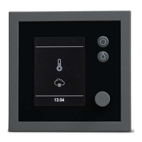
Page 59: Setup During Commissioning Or After A Reset
Commissioning On/off Jog dial: Close sub-menu Turn = select functions or input value. Light on/off Jog dial: Press = confirm functions and settings. Selected icons are displayed inside a white frame. Once the selection is confirmed, the frame turns green and the display now shows the selected function. - Page 60 Commissioning Defining the basic settings Select a language and confirm. Set the time and confirm. Set the date and confirm. Select the type of use and confirm: Private use Commercial use Specific safety regulations apply to this commercial setting. See 1.2 Operator instruction, ...
-
Page 61: Service Settings
Commissioning Service settings Access to the service level is protected by a code. The settings at this level must only be changed by trained personnel. Back Service/Maintenance 11:51 09:21 Service settings Icons The icons displayed depend on the device’s configuration. Service/maintenance ... -
Page 62: Opening Service Settings
Commissioning HOT (only for Finnish operating HOT (only for Finnish operating mode) mode) Configuring the HOT Configuring the HOT function, EN-74 function, EN-74 HOT (only for Finnish operating Setting the ECO function, mode) Configuring the HOT EN-76 function, ... -
Page 63: Service/Maintenance
Commissioning 5.2.2 Service/maintenance You can define the intervals for service/maintenance so that they are in line with operating conditions. The interval is set to 500 hours by the factory. Defining the service interval Open the service settings. See 5.2.1 Opening service settings, EN-62 : Select and confirm. -
Page 64: Fan
Commissioning 5.2.3 You can activate the cabin fan. It is most useful when a vaporiser is in use. Setting the cabin fan Open the service settings. See 5.2.1 Opening service settings, EN-62 : Select and confirm. Setting fan level 0 1 2 09:21... -
Page 65: Refill Period
Commissioning 5.2.4 Refill period Here you can set the time the customer has to refill the vaporiser if there is a water shortage. If water is not added within this time, the vaporiser is switched off (overheat protection). This function is important for Bi-O heat- ers with manual water filling, in particular. -
Page 66: Post-Heating Time
Commissioning 5.2.5 Post-heating time Here you can define the time in minutes for drying after humidity mode. The interval is set to 30 minutes by the factory. According to this setting, the sauna heater is switched on in Finnish mode after humidity mode to dry the sauna. -
Page 67: Post-Heating Temperature
Commissioning 5.2.6 Post-heating temperature If you have connected a steam generator, you can optimize drying of the cabin with a post-heating temperature. If you want to use this function, you should also set a post-heating time. See 5.2.5 Post-heating time, EN-66. ... - Page 68 Commissioning Setting the fan post-cycle period Open the service settings. See 5.2.1 Opening service settings, EN-62 : Select and confirm. fan runtime fan running time with vaporiser 09:21 10:25 Select the operating mode and confirm. Set the time and confirm. fan running time Setting fan runtime...
-
Page 69: Reset Function
Commissioning 5.2.8 Reset function You can perform a factory reset to restore the operating data or all of the settings. Resetting the settings Open the service settings. See 5.2.1 Opening service settings, EN-62 : Select and confirm. Reset 09:21 Select the setting and confirm. -
Page 70: Switch Contacts
Commissioning 5.2.9 Switch contacts A potential-free contact (PFC) is available on the main circuit board (termi- nals 3 and 4). You can switch it on as required or set it to switch on auto- matically. The switch contact can switch in different situations if a code is entered. Codes An “AND”... - Page 71 Commissioning Code Switching condition 7009 The PFC is NO if the sauna is switched on. The PFC is NC after the sauna switches off or switched to post-cycle. Manual operation via the menu is possible at any time. Application: connection for colored light, sound, starlit sky, etc. 7010 The PFC is NO if the sauna is switched on and the heater heats the cabin after the sauna has been switched on.
- Page 72 Commissioning Switching contact manually or with sauna heater Open the service settings. See 5.2.1 Opening service settings, EN-62 : Select and confirm. contact contact Select contact 09:21 09:12 Select the setting and confirm. The potential-free contact is controlled via the main menu. See 6.2.5 Potential-free contact, ...
-
Page 73: 5.2.10 Hot Function
Commissioning Enter the code to switch in specific situations : Select and press and hold the jog dial until the code entry is dis- played. Code Setting Setting Code 7000 09:11 10:51 CAUTION! Entering a code other than 7000 overrides the entries in the menu (... - Page 74 Commissioning Set HOT runtime HOT automatic interval period HOT automatic start time HOT automatic switch-off time Configuring the HOT function Open the service settings. See 5.2.1 Opening service settings, EN-62 : Select and confirm. HOT Auto-Start Setting HOT time 11min 09:21...
-
Page 75: 5.2.11 Configuring The Eco Function
Commissioning 5.2.11 Configuring the ECO function This function allows you to define a period of time in which the cabin tem- perature is lowered and the steam generator is switched off. In the cabin, the ambient temperature is lowered as follows: Calculation –... -
Page 76: 5.2.12 Resetting The Temperature Display
Commissioning Setting the ECO function Open the service settings. See 5.2.1 Opening service settings, EN-62 : Select and confirm. ECO time Setting ECO Time 240min 09:15 11:51 Set the value and confirm. A value between 0 and 240 minutes can be selected in 30-minute in- crements. -
Page 77: Updating Firmware
SD card must be formatted with the FAT32 file system. You can obtain the update from EOS as follows: Card with firmware. ZIP file with the zipped update files as a download from the EOS home page. EmoTec D/H CAN - Installation and Operating Instructions... - Page 78 Commissioning NOTICE Equipment damage due to a faulty update The device can become unusable if the update is interrupted. Ensure that the power supply is not interrupted during the up- date process. The update must be performed by trained personnel only. Ensure that you have a backup of the old software version on your PC or an external drive.
- Page 79 The SD card must be formatted with the FAT32 file system. Preparing the update Download the most recent firmware from the EOS website. eos-sauna.com/service-support/software Unzip the ZIP file you just downloaded and copy it to the formatted memory card.
- Page 80 Commissioning Installing the update NOTICE Ensure that the power supply is not interrupted during the up- date process. Insert the memory card in the card slot on the control panel’s circuit board. Insert it until the card is clearly engaged. Switch the off switch on the relay box to I.
- Page 81 Commissioning Place the front panel directly in front of the housing. Ensure that it is aligned properly. The S-Bus connection must face downward. Position the connecting cable in the bottom piece so that it is not pinched. Press the front panel carefully with a consistent amount of pressure into the housing until it audibly snaps into place.
-
Page 82: Operation
Operation Operation Switching on and off Switching light on/off Press Switching heater on/off Press and hold for approx. 3 seconds until the heater is switched on. 10:51 The cabin is switched on with the pre-set parameters after the count- down. -
Page 83: Functions
Operation Functions 6.2.1 Overview The following functions are available in the menus: Temperature Language 10:51 09:01 Example of overview of functions/menu items Operating mode selection (only Temperature 6.2.3 Temperature, EN-85 if vaporiser is connected) 6.2.2 Operating mode, EN-84 Humidity (Bi-O operating mode, Humidity (Bi-O operating mode, with humidity sensor) - Page 84 Operation Date, Screen saver, Setting the date, EN-91 Setting the time for screen saver activation, EN-92 Standby, Operational lock/child lock, Setting the time for standby Entering the PIN for opera- mode activation, EN-93 tional lock and activating it, ...
-
Page 85: Temperature
Operation Select the operating mode and confirm. Bi-O. Finnish. You can set the humidity for the sauna cabin in the Bi-O operating mode. See 6.2.4 Setting the humidity for Bi-O mode, EN-86. 6.2.3 Temperature The operating mode determines the maximum adjustable temperature. In Bi-O operating mode, the temperature can be set to a value between 30°C and 70°C/86°F and 158°F. -
Page 86: Setting The Humidity For Bi-O Mode
Operation Set the temperature and confirm. The value can be set to any number between 30°C and 70°C/86°F and 158°F. Setting the temperature in Finnish operating mode : Select and confirm. Temperature Temperature Setting for operation without vaporizer (Dry sauna type) 45°... - Page 87 Operation With humidity sensor Humidity is regulated as shown in the table below: All values that lie below or on the characteristic curve can be set and used. When setting a parameter, e.g. temperature, the setting for the other parameter is automatically adjusted.
- Page 88 Operation Setting the humidity : Select and confirm. Humidity Humidity Setting air humidity in % 09:21 10:51 Set and confirm the humidity in percent. The humidity can be set to a value between 20 and 100%; however, it is limited as per the standard curve depending on the target tem- perature.
-
Page 89: Potential-Free Contact
Operation 6.2.5 Potential-free contact The potential-free contact (PFC) is displayed only if you have set the poten- tial-free contact to manual switching. See 5.2.9 Switch contacts, EN-70. You can switch the connected consumer on or off manually at any time. If you activated the potential-free contact for use in the main menu, you can switch it on or off here. -
Page 90: Time
Operation Defining the user interface language : Select and confirm. Language Language 09:01 10:01 Select the setting and confirm. 6.2.7 Time You can adjust the time on the display at any time. Setting the time : Select and confirm. Set the hours and minutes and confirm. -
Page 91: Date
Operation 6.2.8 Date You can set the current date. Setting the date : Select and confirm. Set the year, month and day and confirm your settings. Date Date Date Réglage Réglage l'année 03.01.2019 03.01.2019 09:01 09:22 09:22 Once a setting is confirmed, the next place value is selected. EmoTec D/H CAN - Installation and Operating Instructions EN-91... -
Page 92: Screen Saver
Operation 6.2.9 Screen saver You can set a time after which the screen saver appears on the display. The screen saver is activated only when the system is switched off. Setting the time for screen saver activation : Select and confirm. Start time Screensaver Setting... -
Page 93: 6.2.10 Standby Mode
Operation 6.2.10 Standby mode This setting allows you to define the amount of time after which the con- trol unit switches to sleep mode. Standby mode is activated only when the system is switched off. In sleep mode, the display is completely black. Turn the jog dial to wake the control unit from sleep mode. - Page 94 Operation Entering the PIN for operational lock and activating it : Select and confirm. Keypad lock Keypad lock Setting Code 1234 09:01 09:11 Enter the PIN and confirm. Enter the numbers and confirm each number. Confirmed numbers are displayed in green. ...
-
Page 95: 6.2.12 Heating Time - Auto Stop
Operation Resetting the PIN for operational lock Turn the jog dial briefly. Keypad lock Keypad lock Setting Setting Code Code 0000 0000 09:14 09:14 Confirm the first zero (0). The cursor appears under the second zero. Press and hold down the jog dial for approximately 40 seconds until all four zeros appear white. - Page 96 Operation Setting the heating time : Select and confirm. Auto-Start Auto-Stop Réglage heures 6:00 09:21 09:01 Enter the runtime in hours and minutes and confirm. A line appears under the active place value. If the system is used in a private setting, the heating time is limited to 6 hours.
-
Page 97: Operating Data
Operation 6.2.13 Operating data You can retrieve data on the control unit’s current firmware version for the control panel, the modules and the service interval. Retrieving the firmware version and unit serial number, EN-97 Retrieving the next service date, EN-98 ... - Page 98 Operation Use the jog dial to choose the display for the control panel or for the re- lay box. Firmware version Firmware version Serial 003123456 Serial 030123456 Panel M.-LS R 3.30 R1.00 09:11 09:11 Examples for the displayed values ...
- Page 99 Operation : Select and confirm. Service/Maintenance Operation data Time remaining until recommended maintenance Service/Maintenance 500 h 09:13 09:15 The amount of time remaining until the next service date is dis- played. The operation time is set to 500 hours by the factory. ...
-
Page 100: 6.2.14 Display Brightness
Operation : Select and confirm. Contact data Operation data EOS Saunatechnik GmbH Schneiderstriesch 1 35759 Driedorf Germany Tel: +49 (0)2775 82-514 Contact data Fax: +49 (0)2775 82-431 servicecenter@eos-sauna.de www.eos-sauna.de 09:15 09:15 6.2.14 Display brightness You can adjust the display’s brightness to accommodate environmental conditions. -
Page 101: Holiday Cottage Mode
The control unit cannot be used if the PIN is not known. Save the PIN in a safe place. Contact your retailer or EOS Service if you lose your PIN. If the holiday cottage mode is active, the language selection is displayed first after the system is switched on again by pressing the main switch. - Page 102 Operation Entering the PIN for holiday cottage mode and activating it : Select and confirm. Enter the PIN and confirm. Holiday home mode Holiday home mode Setting Code for locking 1000 09:01 09:11 Enter the numbers and confirm each number. Confirmed numbers are displayed in green.
-
Page 103: Malfunction
Battery in the control The battery may be replaced setting unit defective. only by a qualified specialist. Other errors Software error. Restart the control unit. Contact EOS Service. See Service address, EN-108. EmoTec D/H CAN - Installation and Operating Instructions EN-103... -
Page 104: General Terms And Conditions Of Service
General terms and conditions of service General terms and conditions of service (T&C, Dated 08-2018) I. Scope Unless otherwise agreed in writing for specific instances, these terms and conditions of service shall apply to service operations, including reviewing and remedying complaints. All our existing or future legal relationships shall be governed solely by the following terms and conditions of service. - Page 105 General terms and conditions of service IV. Service visit by the manufacturer Services rendered on site by an employee of the manufacturer must be agreed in advance. If the main reason for the service visit is not the fault of the manufacturer, any costs incurred shall be charged to the customer after the service visit and must be paid by the customer in full within the agreed payment term.
- Page 106 Complaints in respect of our products shall be reported to the responsible distributor and shall be handled exclusively by said distributor. The manufacturer’s General Terms and Conditions of Business, in the ver- sion available at www.eos-sauna.com/agb, shall apply in addition to the foregoing terms and conditions of service. EN-106...
-
Page 107: Disposal
Disposal Disposal Observe local provisions, laws, regulations, standards and direc- tives when disposing of the unit. Do not dispose of the unit with household waste. Packaging The packaging of the unit can be completely separated for disposal and recycled. The following materials are used in the packaging: ... - Page 108 Store this address with the installation and operating instructions in a safe place. Please always provide us with nameplate data, such as model, item num- ber and serial number so we can provide fast and efficient support. Date of sale Stamp/retailer signature: © EOS Saunatechnik GmbH - All rights reserved.
Need help?
Do you have a question about the EmoTec H CAN and is the answer not in the manual?
Questions and answers