EOS Econ D2 Installation And Operating Instruction
Sauna control unit
Hide thumbs
Also See for Econ D2:
- Assembly and operating instructions manual (32 pages) ,
- Quick start manual (2 pages)

Related Manuals for EOS Econ D2


Summary of Contents for EOS Econ D2
- Page 1 EOS Econ D2 sauna control unit Installation and operating instruction Made in Germany Firmware R4.35 IPx4 Print no. 29344706en / 30.22 Technical changes reserved...
-
Page 2: Table Of Contents
English Table of contents General safety instructions ..........................4-8 Safety levels ..............................4 Mounting and electrical installation ....................5-6 Operator instruction ..........................6-8 Standards and regulations ........................8 Identification .................................9 Scope of delivery .............................. 10 Accessories ................................. 10 Technical data ..............................11 Intended use ..............................12 Installation of the control unit .......................13-16 Installation site ............................ - Page 3 Individual settings............................30-34 Cabin temperature ........................... 30 Auto-stop / heat-up time limitation....................31 Cabin lighting............................. 32 Preselection time ............................33 Activate / deactivate the preselection time ..................34 Advanced settings .............................35-38 Change language ............................. 35 Change time ............................... 35 Switching between °C and °F ....................... 36 Switching user profiles (P1-P4) ......................
-
Page 4: General Safety Instructions
General safety instructions Safety levels Safety instructions and important operating instructions are classified. Please familiarise yourself with the following terms and symbols: WARNING Warning Indicates a hazardous situation which, if not avoided, could result in death or serious injury. CAUTION Caution Indicates a hazardous situation which, if not avoided, could result in minor or moderate in- jury. -
Page 5: Mounting And Electrical Installation
Mounting and electrical installation These installation instructions are intended for qualified personnel familiar with the laws and regulations applicable to electrical installations at the installation site. Observe the following general safety instructions during mounting, config- uration and commissioning of the product. Risk to life and limb and risk of fire Risk to life and limb from electric shock and fire in the event of improper or faulty electrical connection. -
Page 6: Operator Instruction
Damage to the unit Corrosive or heavy saline atmospheres damage the contacts in the control panel, in the relay box and in the sensors. The control panel and sensors should not be installed in a corrosive or heavy saline atmos- •... - Page 7 Fire hazard Objects placed on the sauna heaters can ignite and cause fire. Do not place objects on the sauna heater. • If you switch on the sauna heater using a pre-set timer or a remote control, use a cover •...
-
Page 8: Standards And Regulations
For an overview of the standards that were observed during design and construction of the sauna heaters, please refer to the individual product‘s technical data sheet that can be downloaded from www.eos-sauna.com. Local regulations also apply to the installation and operation of heating, sauna, and steam... -
Page 9: Identification
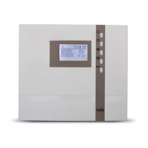
Identification The Econ D2 control unit consists of a main unit, a temperature sensor with connecting cables and small accessories, and is used to operate a sauna cabin. Additional devices can be connected to the control unit for control of a sauna cabin, for example, lighting and power extension devices. -
Page 10: Scope Of Delivery
Scope of delivery Delivery contains the following items: 1. Control unit Econ D2 2. Temperature sensor kit, comprising Sensor housing (a) ƒ Board with temperature sensor KTY and safety temperature limiter (b) ƒ 2 mounting screws 4 x 40 mm (c) ƒ... -
Page 11: Technical Data
Technical data Voltage (power supply) 400 V 3N ~ 50 Hz Switch output max. 9 kW resistive load (AC1 mode). Can be expanded to 36 kW via the connection of power switching devices Fuse 3 x 16 A Heating time limit: 6 h, 12 h Display LCD display 65 x 37 mm, graphic... -
Page 12: Intended Use
Intended use In conjunction with a suitable sauna heater, the Econ D2 control unit is intended to be used only to heat sauna cabins. It is suitable for residential and commercial sauna cabins. Any further use is deemed not to be in accordance with the intended purpose! The intended use also includes compliance with the usual operating, maintenance and servicing conditions. -
Page 13: Installation Site
Installation All lines should be routed before installing the control unit. The connections can be plugged in after installation, since the control unit’s front panel can be removed. NOTICE Electronics malfunctions Routing data and power supply lines together can lead to electronics malfunctions because, e.g. because the sensor will not be detected. -
Page 14: Installing The Control Unit
WARNING Risk to life and limb and risk of fire Risk to life and limb from electric shock and fire in the event of improper or faulty electrical con- nection. This risk also applies following completion of the installation work. Do not install relay boxes in enclosed cabinets or wood panelling. - Page 15 NOTICE Damage due to steam and humidity Condensation can form when the door is opened, which can fog over the display. This can lead to the formation of condensation in the control unit and malfunctions. Mount the control unit outside of the area in which the humid warm air mixture can spread. ƒ...
- Page 16 Mounting the unit on the wall ca. 35 cm Drill one (1) hole above and two (2) holes with Ø3 mm in the wall as shown. Screw in the upper screw. Allow the screw to protrude approx. 3 mm so you can later hook in the hous- ing.
-
Page 17: Connecting The Sensor Cables
Connecting the sensor cables You should not install sensor and power supply 20 cm lines together, or lead them through the same feedthrough. This can lead to interferences in the electronics, such as "fluttering" in the re- lays. If it is necessary to lay the cables down together, or if the line is longer than 3m, use a shielded sensor cable (4 x 0.5 mm²). - Page 18 Bore hole Sauna ceiling Centre sensor housing on middle section of the wooden plank. Sensor cables connect to ground (PE) by shielded sensor cable Fig. 11 Notice Equipment damage due to incorrect connection. Mixing up the connection on X2 connection can cause the fuse F2 to blow and damage the control (for replacement please refer to the chapter „Device fuses“) Temperature sensor...
-
Page 19: Electrical Installation
Electrical installation This chapter describes how to connect the relay box‘s circuit board lines. For information on setup of the control panel, see chapter Commissioning Recommended installation sequence Before commencing installation, ensure that the control unit and the temperature sensor are mounted. -
Page 20: Connection Diagram For Sauna Heaters Up To 9 Kw
Connection diagram for sauna heaters up to 9 kW 139°C ECON L1 L2 L3 V1 N S1 Limiter weiß / white Sensor rot / red max. 100 W 3x16A P max. 9 kW 400 V 3N ~ 50 Hz Connection diagram for sauna heaters above 9 kW 139°C ECON L1 L2 L3... -
Page 21: Main Board Assignment And Components
Main board assignment and important components L1 L2 L3 N W V U N Upper circuit board with LCD display Sauna heater connection LCD display Light connection Lower circuit board (Power unit) F2 Fine fuse T 315 mA L 250V F1 Fine fuse T 2A H 250 V Connection heater sensor and protection temper- ature limiter (X2 terminal block) -
Page 22: Connecting The Sensor Cables
The control unit may be damaged if the STB and sensor lines are interchanged.. • Always connect the safety temperature limiter (STB) as an isolated contact. • If the installation uses multiple sauna heaters, multiple safety temperature limiters may be required. Observe the separate EOS instructions. -
Page 23: Connecting The Consumer Lines
Connecting the consumer lines WARNING Risk of electric shock There is a risk of electric shock when connecting the cables if the control unit is connected to the power supply. Ensure that the control unit has no power. ƒ Required tools: Flathead screwdriver Connecting the sauna heater Connect the cable from the sauna heater to the four terminals (oven) W, V, U, N and PE. -
Page 24: Operation
Operation Once the system has been installed with all components and all covers have been fixed, you can put the control unit into operation. Please read the following information to get yourself familiar with the functions and capabilities of your sauna control unit. General information The user interface MODE... -
Page 25: Default Display Stand-By
Default display Stand-by 12:00 is shown if the system is in Stand-by mode. Temperature 90°C The system also returns to this screen from Auto-stop 5 : 59 other menu items, if there is no activity for >15 Start time - - : - - seconds. -
Page 26: Symbol Description
Symbol description 12:00 The following is shown in the top area of the display: Light switches on automatically when heating is switched on Light-Symbol • Light stays on 30 min. after the heating stops • Manual light switching is possible at any time •... -
Page 27: Operation Principle
Operation principle For settings press shortly the button. MODE The first parameter (temperature) will be se- lected and shown inverted. 12:00 Use the buttons to navigate to the Temperature 90°C required parameter which you would like to Auto-Stop 5:59 Start time - - : - - adjust. -
Page 28: Initial Commissioning
Initial commissioning Set language (DE, GB, IT, NL, PL, RU, FR, SE, ES, CZ, FI, SLO) 12:00 12:00 MODE > 3 Sec Set time of day (0:00 bis 23:59) 00:00 00:00 Time of day Time of day : 00 : 00 MODE 00:00 00:00... -
Page 29: Switching Your Sauna On / Off In Dry Mode
Switching your sauna on in a dry (Finnish) mode 12:00 12:15 Temperature 90°C Temperature 30°C Auto-stop Auto-stop 5 : 59 5 : 59 Start time - - : - - - - : - - Start time > 3 sec Switching your sauna off (dry sauna mode) 12:00 12:15... -
Page 30: Individual Settings
Individual Settings The following are options for adapting the control systems to your individual needs. The parame- ters can be adjusted both in standby or in operation mode and the changes are then saved in the device. Changes made in operation mode will apply immediately once saved. Cabin temperature Setting range: Dry sauna operation 30 - 115°C... -
Page 31: Auto-Stop / Heat-Up Time Limitation
Auto-stop / heat-up time limitation Auto-Stop defines the heating time limitation. The sauna unit automatically turns off once this time has expired. Depending on the configuration of the control unit, a time between 0:30 to 6:00, 0:30 to 12:00 hours can be set. This setting is valid for all user profiles P1-P4. Attention! The allowed time for private operations is 6 hours. -
Page 32: Cabin Lighting
12:00 12:00 Temperature 90°C Temperature 90°C Auto-stop 3 : 5 9 Auto-stop 3:30 Start time - - : - - Start-time - - : - - > 3 sec. > 3 sec. MODE MODE 12:00 12:00 Temperature 90°C Temperature 90°C Auto-stop 3 : 3 0 Auto-stop... -
Page 33: Preselection Time
Preselection time The switching time preselection function is a timer which allows you to automatically switch your sauna up to 24 h in advance or enable recurring automatic switching. Note: by disabled Safety the time pre-selection will be shown but cannot be programmed. Single-even switching: Set start time up to 24 h in advance and press On/Off button shortly. - Page 34 12:15 12:15 Temperature 30°C Temperature 30°C Auto-stop Auto-stop 5 : 59 5 : 59 17 : Start time 17 : Start time 12:15 12:15 Temperature 30°C Temperature 30°C Auto-stop Auto-stop 5 : 59 5 : 59 Start time Start time 17 : 17 : MODE...
-
Page 35: Advanced Settings
Advanced settings Change language Change time 12:00 12:00 Temperature 90°C Temperature 90°C Auto-stop 5 :5 9 Auto-stop 5: 59 Start time - - :-- Start time -- : -- & MODE & MODE 12:15 12:00 Time of day Time of day 12 : 15 12 : 00 MODE... -
Page 36: Switching Between °C And °F
Switching between °C and °F You can select between °C or °F display if you switch the controler off and then switch it on again while holding the button pressed. 12:00 Temperature 50°C Auto-stop 5 : 5 9 Start time - - : - - &... -
Page 37: Activate / Deactivate The Child Lock
Activate / deactivate the child lock Activate / deactivate the Safety (only with existing safety system) If the child lock is activated (the key symbol is visible in the top section of the display) only the If Safety is not activated, neither the one-time cabin lighting can be switched. -
Page 38: Activate / Deactivate The Life - Guard
Activate / deactivate the Life - Guard Life - Guard is a settable relatively short time, e.g. 20 minutes, after which the sauna unit is switched off, except for the cabin lighting. After this time has expired the unit can be switched on again by pushing the -button for the set MODE... -
Page 39: Life-Guard
Life-Guard Here you can set a short period of time after which the sauna will be automatically switched off (interrupted) and may be immediately restarted for the same period of time by pressing the MODE button. For example, set up 15 minutes. If you do not press the button again after 15 minutes, the sauna heater will switch off. -
Page 40: Switching On The Sauna Unit With Life-Guard
Switching on the sauna unit with Life - Guard 12:00 Temperature 90°C Auto-stop 5 : 5 9 Start time - - : - - Life - Guard 20 min > 3 sec 12:00 Temperature 90°C Auto-stop 5 : 5 9 Start-time - - : - - Life - Guard... - Page 41 Holiday home mode Holiday park mode Symbol flashes The holiday home mode allows the control In the holiday park mode, all functions are de- system to be blocked so that only the most es- activated apart from Sauna and Light (On/Off ). sential functions are visible and can be set.
-
Page 42: Heating Time Limitation
Heating time limitation The maximal heating time may be set with a jumper on the display printed circuit board to 6 or 12 hours or to unlimited operation time. The jumper is located at the top edge of the board as shown below. -
Page 43: Device Fuses
Device fuses The control unit is fitted with two protective fuses which are mounted on the main relay board of the unit. These fuses protect the electronics on the board and the light and fan outputs. Notice: fuses do not mean absolute protection, in an unlikely case of a power surge or a short circuit with particularly fast voltage increase the electronic components may be still be affected. -
Page 44: Error Messages
Error messages The control unit continuously monitors the sensor for short circuits and interruptions. The error messages appear as follows: Display Cause Remedy = interrupted room sensor circuit Arrange for a specialist to 12:00 The temperature sensor (KTY) is check the lines and KTY. faulty, or the line to the temperature Sensor - KTY at 20°C approx. -
Page 45: The Device „Switch-Off" Switch
The device „Switch-off“ switch The control unit is equipped with a “Switch-off” Switch-off rocker rocker switch. You will find this switch on the top side of the housing by Econ series control units. This switch allows to switch the control unit to the standby mode (notice the heating will not start), to switch the control unit completely off (disconnect from power) or to switch the con-... - Page 46 Diese Seite wurde absichtlich leer gelassen This page has been intentionally left empty...
-
Page 47: Recycling
2012/19/EU. Do not dispose it with the normal household waste. Service Address: EOS Saunatechnik GmbH Schneiderstriesch 1 35759 Driedorf, Germany Tel: +49 (0)2775 82-514 Fax: +49 (0)2775 82-431 servicecenter@eos-sauna.de... -
Page 48: General Terms And Conditions Of Service
The manufacturers General Terms and Conditions of Business, which can be found at www.eos-sauna.com/ V. Liability agb, shall apply in addition to the foregoing terms and conditions of service.
Need help?
Do you have a question about the Econ D2 and is the answer not in the manual?
Questions and answers