
Related Manuals for AMGO A435-P


Summary of Contents for AMGO A435-P
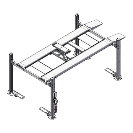
- Page 1 Your safety our standards Installation and service manual 4.5T(10000lbs) FOUR-POST PARKING LIFT...
-
Page 2: Table Of Contents
CONTENTS I. Product Features and Specifications………….………………………... ………… 1 II. Installation Requirement ……….……….……….…………………. ………………. 2 III. Steps of Installation……………………….…………....….………….3 IV. Exploded View………………………….………………….. …….. ….. …….. ….29-36 V. Test Run………………………...……………………………………………………………37... -
Page 3: Product Features And Specifications
I. PRODUCT FEATURES AND SPECIFICATIONS 4-POST MODEL A435-P FEATURES ingle point manual safety release. ● S Four mechanical locking devices, each equipped with both primary ● and secondly safety locks. Powerside column can be installed at both side, front or rear. -
Page 4: Installation Requirement
II. INSTALLATION REQUIREMENT TOOLS REQUIRED Tape Measure (7.5m ) Carpenter’s Chalk Hammer Screw Sets Level Bar Pliers English Spanner (12") Lock Wrench Wrench set :(12 # # # # # 、13 、14 、15 、17 、19 Socket Head Wrench :(3 # #... -
Page 5: Steps Of Installation
2. Concrete must be in good condition and must be of test strength 3,000psi (210kg/cm²) minimum. 3. Floors must be level and no cracks. (See Fig. 3) Concrete must be of test strength Fig.3 210KG/ c ㎡. C. POWER SUPPLY The electrical source must be 2.2KW minimum. - Page 6 Safety Parts box andOther Lock Platform small items Cross CAR ramp LeverS Power Unit Column electrical Platform beam box is behind Note: Parts may be located in different parts in different batches Fig.5( 3. Take off the drive-in ramps and The platform above (See Fig.6) 4.
- Page 7 Fig.8 6. Check the parts of the parts bag (See Fig. 9)
- Page 8 Use a carpenter’s chalk line to establish installation layout as per Table 1 Make sure the size is right and base is flat (see Fig. 10) Note: Reserve appropriate space in front and behind the installation site. 4.5T 5019mm 3204mm 5954mm 4.5T 197.6”...
- Page 9 Install cross beams (See Fig.11, Fig.12) Note: Pay attention that the cross beam's slot should be positioned towards inward and the safety locks connecting assy. should be adjacent to the power unit column. The powerside column need to be installed according to the installed position of the safety lock release handle.
- Page 10 D. Install the Safety Ladders. adjust the four lower nuts so they are at the same position. Then insert the safety ladder (See Fig. 13). Main crossbeam...
- Page 11 2. Install Safety Ladders (See Fig. 14) This height for four threaded rod of safety ladders should be the same. Fig.14 Safety ladder pass through the hole of the top plate, then tighten the two nuts E. Raise the cross beams at the same height and lock them on the safety ladders (See Fig.
- Page 12 F. Install power side platform. 1. Raise the powerside platform above the cross beam by a forklift or crane. Then move the cross beam outwards until the pulleys of both platforms can be rested into the cross beams’ slots ( see Fig.16 ). Tighten the Powerside Platform to the Cross beams by using bolts. Offset the cross beam lean outward when putting the powerside platform on the...
- Page 13 2. Install the tire stop plate and connecting bolts: Tighten the platform and the cross beam 1 with bolts. Tighten the tire stop plate , platform and cross beam 2 with bolt. Note: Install the tire stop plate on the drive- in position . And the bolts for connecting with tire stop plate is longer, pay attention when choosing the bolts.
- Page 14 G. Install the offside platform and limit slide block, and platform strengthen bolts. Check the verticality of columns with level bar and adjust with shims. (See Fig. 18) Fig.18...
- Page 15 H. Illustration for Wire Rope installation 1. Route theWire Rope from the powerside platform via the pulleys according to the number below and then connect them to the columns. (See Fig. 19) ○ ○ ○ ○ Wire Rope Length 4782mm 8135mm 3156mm 9762mm...
- Page 16 2. The cable goes through the cross beam to column top plates and tightened with cable nuts (See Fig. 20) The wire rope passes through The wire rope wheel passes the cross beam, the wire rope through the upper cover plate wheel and the guide wheel of the post and is tightened with the wire rope nut...
- Page 17 Illustration for cables under platform . (See Fig. 21) Wire Rope 1 Hexagon head bolts M8 * 100 Wire Rope 2 Hexagon head bolts M8 * 100 Wire Rope 4 Wire Rope 3 Hexagon head bolts M8 * 100 Wire Rope 2 Hexagon head bolts M8 * 100 Wire Rope 1 Hexagon head bolts M8 * 100...
- Page 18 I. Install release handle assy. (See Fig. 22) Noted: Power unit must be installed near the safety release handle. Cross beam B Picture B Cross beam A Picture A Lock welded connecting Connecting thread pull rod assembly for unlocking Unlock Thread Tie Rod Assembly Fig.
- Page 19 J. Install power unit and connecting tube (See Fig. 23) Noted: Power unit must be installed near the safety release handle. 1.Install Power unit on the cross beam A Cross beam B Cross beam A Connector fixing plate M8x35, hexagon socket head bolts are used to secure the connecting pipe and connecting rod of the safety device...
- Page 20 Install Power unit on the cross beam B (See Fig. 24) Beam B Connector fixing plate Fix The connecting pipe and connecting rod of the safety device with the six-bolt in the M8 * 35...
- Page 21 K. Install Hydraulic System (See Fig. 25) Return connection Fig. 25 Oil tubing connection route Return connection route...
- Page 22 L. Install the control box( See. Fig.26) (Electric control box is optional) Fig.26 Note: When the cross beam goes to highest place, the cross beam slide block touched the high limit switch drive bar and the lift stop rising.
- Page 23 M、 Circuit diagram (See Fig. 27)
- Page 24 N.Install spring and beam safety cover of cross beam Fig.2 8 (See Fig. 28 Install drive-in ramp, optional jack tray and optional oil pans (See Fig. 29) then attach the drive-in ramp. Install drive- in ramp optional optional oil pans jack tray Fig.
- Page 25 O. Install front wheel platform baffles (See Fig. 30) Fig.30 For optional kits installation 1. Install optional caster kits or jack(asembly body)------- optional (See Fig. 31) Fig.31...
- Page 26 2. Install motor fixing bracket (See Fig. 32) Fig.32 Q. Fix the anchor bolts 1. Prepare the anchor bolts (See Fig. 33) Spring washe Washer Fig.35 1.2 Adjust the column with the leveling bar and leveling pad , drill the anchor hole and install the anchor bolts.
-
Page 27: Exploded View
IV. EXPLODED VIEW... - Page 28 Main crossbeam...
- Page 29 Detail table of main crossbeam decomposition...
- Page 30 Secondary Crossmember...
- Page 31 Analytical List of sub-crossmember...
- Page 32 List of other machine parts(Refer to the text breakdown diagram)...
- Page 34 Motor Function Analysis Throttle valve Check valve Release valved Oil outlet Handle for release valve Check valve :Prevent reverse flow of oilOverflow Overflow valve Overflow valve :Adjusting oil pressure Throttle valve :Adjusting the descent rate...
- Page 35 Motor drawing and part list...
-
Page 36: Test Run
V. TEST RUN 1. Fill the reservoir with Hydraulic Oil Press buttonControl box till the cables are strained. Check the cables and confirm they are in the proper pulley position. Make sure the cables are not across 3.When the Power Unit pressure relief valve is pressed down, the cross beam will be locked to the safety ladders and then adjust the platforms to be level by adjusting the nuts of safety Ladder.
Need help?
Do you have a question about the A435-P and is the answer not in the manual?
Questions and answers