Table of Contents
Advertisement
Quick Links
Advertisement
Table of Contents

Related Manuals for AMGO A435-P


Summary of Contents for AMGO A435-P
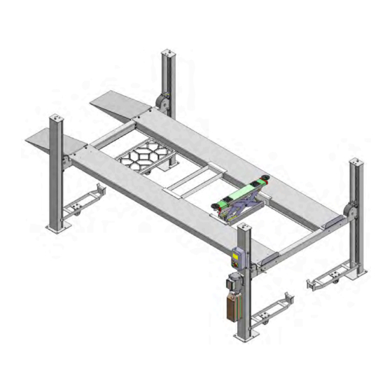
- Page 1 FOUR-POST PARKING LIFT Model: A435-P Fig. 1...
-
Page 2: Table Of Contents
CONTENTS I. Product Features and Specifications………….………………………... ………… 1 II. Installation Requirement ……….……….……….…………………. ………………. 2 III. Steps of Installation……………………….…………....….………….3 IV. Exploded View………………………….………………….. …….. ….. …….. ….. …30 V. Test Run………………………...……………………………………………………………35 VI. Operation Instruction……………………….……..……………………………………36 VII. Maintenance…………………….…………..……………………..…………………….37 VIII. Trouble Shooting………………….………………..………..…………..………..…37 IX. Parts List……….…………….………………..………..…….. …..………..…….. …..38... -
Page 3: Product Features And Specifications
I. PRODUCT FEATURES AND SPECIFICATIONS 4-POST MODEL A435-P FEATURES ● S ingle point manual safety release. ● Four mechanical locking devices, each equipped with both primary and secondly safety locks. ● Powerside column can be installed at both side, front or rear. -
Page 4: Installation Requirement
II. INSTALLATION REQUIREMENT TOOLS REQUIRED P Tape Measure (7.5m ) P Carpenter’s Chalk P Hammer P Screw Sets P Level Bar P Pliers P English Spanner (12") P Lock Wrench P Wrench set :(12 # # # # # 、13 、14 、15 、17... -
Page 5: Steps Of Installation
2. Concrete must be in good condition and must be of test strength 3,000psi (210kg/cm²) minimum. 3. Floors must be level and no cracks. Concrete must be of test strength 210kg/ cm² minimum. Fig.3 C. POWER SUPPLY The electrical source must be 2.2KW minimum. The source cable size must be 2.5mm² and in good condition of contacting with floor. - Page 6 Powerside Offside Cross Drive-in Column Parts Platform Platform Beam Ramp 板 Shipment Parts List Fig.5 3. Take off the drive-in ramps and columns (See Fig.6) Fig.6 4. Loosen the screws of the upper package stand, take off the offside platform, take out the parts inside the powerside platform, then remove the package stand.
- Page 7 6. Open the carton of parts and check the parts according to the parts box list (See Fig. 8) Fig.8 7. Check the parts of the parts bag according to the parts bag list (See Fig. 9) Fig.9...
- Page 8 Make sure the size is right and base is flat (see Fig. 10). Note: Reserve appropriate space in front and behind the installation site. Use a carpenter’s chalk line to establish installation layout Fig.10 MODEL A435-P 4400mm 2784mm 5207mm 173 1/4” 109 5/8” 205”...
- Page 9 C. Install cross beams (See Fig.11, Fig.12) Note: Pay attention that the cross beam's slot should be positioned towards inward and the safety locks connecting assy. should be adjacent to the power unit column. The powerside column need to be installed according to the installed position of the safety lock release handle.
-
Page 10: See Fig.
D. Install the Safety Ladders. 1. Take off the pulley safety cover and unscrew the four upper nuts of the safety ladders, and adjust the four lower nuts so they are at the same position. Then insert the safety ladder (See Fig. - Page 11 2. Install Safety Ladders (See Fig. 14) This height for four threaded rod of safety ladders should be the same. Fig.14 Safety ladder pass through the hole of the top plate, then tighten the two nuts E. Raise the cross beams at the same height and lock them on the safety ladders (See Fig.
- Page 12 F. Install power side platform. 1. Raise the powerside platform above the cross beam by a forklift or crane. Then move the cross beam outwards until the pulleys of both platforms can be rested into the cross beams’ slots ( see Fig.16 ). Tighten the Powerside Platform to the Cross beams by using bolts. Offset the cross beam lean outward when putting the powerside platform on the...
- Page 13 2. Install the tire stop plate and connecting bolts: Tighten the platform and the cross beam B with bolts. Tighten the tire stop plate , platform and cross beam A with bolt. Note: Install the tire stop plate on the drive- in position . And the bolts for connecting with tire stop plate is longer, pay attention when choosing the bolts.
- Page 14 G. Install the offside platform and limit slide block, and platform strengthen bolts. Check the verticality of columns with level bar and adjust with shims. (See Fig. 18) Install the platform strengthen bolts. Level bar Slip the limit slide block with groove into the clearance along the bent edge of column.
- Page 15 H. Illustration for cable installation 1. Route the cable from the powerside platform via the pulleys according to the number below and then connect them to the columns. (See Fig. 19) ○ ○ ○ ○ Cable Length 2940mm 8535mm 4350mm 7120mm (inc.
- Page 16 2. The cable goes through the cross beam to column top plates and tightened with cable nuts (See Fig. 20) Cable goes through top plate and tightened with cable nuts. Cable goes through the cross beam pulley and tension pulley Fig.20...
- Page 17 3. Illustration for cables under platform . (See Fig. 21) limit block ○ Cable ○ Cable ○ Cable ○ Cable ○ Cable ○ Cable ○ Cable ○ Cable ○ Cable ○ Cable ○ Cable ○ Cable ○ Cable ○ Cable Hex Bolt M10*120 Fig.21...
- Page 18 I. Install release handle assy. (See Fig. 22) Noted: Power unit must be installed near the safety release handle. Cross beam B View B Cross beam A Fig. 22 View A Safety lock Safety lock rotated connecting assy. device assy. Safety lock connecting bar According to the above diagram, fix lock release...
- Page 19 J. Install power unit and connecting tube (See Fig. 23) Noted: Power unit must be installed near the safety release handle. 1.Install Power unit on the cross beam A Drive- in direction Cross beam B Cross beam A Fig. 23 View A Fixing plate Connecting tube pass...
- Page 20 Install Power unit on the cross beam B (See Fig. 24) Cross beam B Fig. 24 Drive- in direction Fixing plate Connecting tube pass through the fixing plate Fix the connecting tube and the connecting bar for safety device by M8*25 socket bolts K.
- Page 21 Retaine r Oil return Oil return hose passed Oil inlet port inclined hose above the cable upwards c、d 4 55 Fig.25 The oil hose and oil return hose pass through the protective hose and connect to the power unit For power unit attached to the column for cross beam B (See Fig.
- Page 22 L. Install the control box and limit switch( See. Fig.27) Install high limit switch Install low limit switch Block Cross beam Limit switch drive bar 520m Note: When the cross beam goes to highest place, the cross beam slide block touched the high limit switch drive bar and the lift stop rising. Fig.27 When the cross beam lower to 520mm from ground, the cross beam slide block touched the low limit switch drive bar and the lift stop...
- Page 23 1.Wire connecting for high limit switch 90º Connecting 11 & 12 (NC) of limit switch to terminals 3 & 5 control box 2、Wire connecting for low limit switch wire 90º Connect limit switch 11 & 12 terminal to control box 1 &...
- Page 24 M. Install electrical system 1. Connecting wire with control box. ( See. Fig.28) Note: 1) Specification of wire of limit switch and Air solenoid valve is Specification of power source wire and motor wire : 4*2.5 2) Using white bobbin to wind around wire. 3) Fix the cable of limit switch on the column with retainer, tie the wire with protective hose by the cable ties.
- Page 25 1.5HP 2.0HP Hydraulic power unit Single phase 3 phase Rated current of thermal relay This point shows Using cross the present screwdriver to rated current adjust rated value current value of thermal relay Fig.29 3. 380V Wire connection and circuit diagram Wire connection diagram in the control box (See Fig.
- Page 26 3.2 Wire connection diagram of Three phase hydraulic motor (See Fig. 31) Motor wire (M1、M2、M3) are connected to the three wires in the motor. Turn on the power, push button “UP”, if motor run but lift do not work, pls. change the wire M1 and M2 connection.
- Page 27 4、220V Wire connection and circuit diagram 4.1 Wire connection diagram in the control box (See Fig. 33) Solenoid Power High Motor wire Earth valve wire source limit limit wire wire switch switch Fig.33 4.2 Wire connection of single phase hydraulic power unit( See fig.34) Motor wire (M1、M2) separately connected to two terminals in the control box 。...
- Page 28 220V Circuit diagram (See Fig. 35) 1 phase Fig.35 220V Circuit component Item Name Code Specification Item Name Code Specification Power switch 380V AC duplex Lowering alarm button Fuse Motor Single phase Fuse Transformer 24V AC AC contactor Limit switch 、...
- Page 29 N. Install spring and safety cover of cross beam (See Fig. 36). Fig.36 O. Install drive-in ramp, optional jack tray and optional plastic oil pans (See Fig. .According to the below diagram screw the M16*30 bolts, then attach the drive-in ramp.
- Page 30 P. Install Rear wheel stop plates (See Fig. 38) After driving the vehicle on the lift, take off the drive-in ramp, install rear wheel stop plates to the drive-in ramp position. Fig.38 Q. For optional kits installation 1. Install optional caster kits or jack (See Fig.
- Page 31 2. Install optional motor fixing bracket (See Fig. 40, Fig 41) Motor fixing bracket on the Motor fixing bracket on the side side of cross beam A of cross beam B Fig.40 Fig.41 R. Fix the anchor bolts 1. Prepare the anchor bolts (See Fig.
-
Page 32: Exploded View
IV. EXPLODED VIEW Model: A435-P Fig.44... - Page 33 CROSS BEAM Fig.45 Control box Fig.46...
- Page 34 CYLINDERS Fig.47 SPX ELECTRIC POWER UNIT 220V/50HZ, single phase (Fig. 48) Fig.48...
- Page 35 PEAK ELECTRIC POWER UNIT (Fig. 49,50) 220V/50HZ, 1 Phase 380V/50HZ, 3 phase Fig. 49 Fig. 50 Illustration of hydraulic valve for SPX & PEAK hydraulic power unit a. SPX Electric power unit, 220V/50HZ, Single phase (See Fig. 51) Capacitor Relief valve Oil return port Solenoid valve Auxiliary hole...
- Page 36 b. PEAK electric power unit, 220V/50HZ, 1 phase (See Fig. 52) Running capacitor Start capacitor Relief valve return port Throttle valve Solenoid valve Check valve Outlet Fig.52 C. PEAK electric power unit, 380V/50HZ, 3 phase (See Fig. 53) Relief valve return port Throttle...
-
Page 37: Test Run
V. TEST RUN Fill the reservoir with approximately 12L Hydraulic Oil (Note: In consideration of Power Unit’s durability,please use Hydraulic Oil 46# ) ; Press button till the cables are strained. Check the cables and confirm they are in the proper pulley position. Make sure the cables are not across Press button Down1 ,... -
Page 38: Operation Instruction
VI. OPERATION INSTRUCTIONS A. To lift vehicle 1、Keep work area clean around and near the lift; 2、Drive vehicle to the Platform and put on the brake; 3、 Take off the drive-in ramp and install rear wheel stop plates to the drive-in ramp position. 4、Turn on the power source switch , press button UP and rise the lift to the working position. -
Page 39: Maintenance
VII. MAINTENANCE Monthly: 1. Lubricate cable with lubricant; 2. Inspect if there is crack for all the cables; 3. Make a visual inspection if abrasion and leakage for all the hydraulic hose/lines; 4. Lubricate the pulley and safety device with gear oil. Every six months :... -
Page 40: Parts List
IX. PARTS LIST FOR MODEL A435-P Item Part# Description QTY. Note 410110 Powerside Column 410002 Offside Column 410003 Cross Beam A 410004 Offside Platform 410005 Powerside Platform 410006 Cross Beam B 410007 Drive-in ramp 209043 Hex Bolt 209033 Washer 209005... - Page 41 Item Part# Description QTY. Note 209032 Socket bolt 217005 Plastic ball 209056 Self locking Nut 410025 Socket bolt 410026 Safety release handle 410100 Extension lock release handle assy 209004 Rubber ring 209003 Hex Bolt 420166 Fitting 420119 Straight Fitting for cylinder 410135 Limit block 410027...
- Page 42 Optional kits 410040 Jack tray 410039 Plastic oil tray 40801 Caster kits 410041 Sliding jack 40802 Motor fixing bracket Parts for optional caster kits 410042A Support bracket 76-1 76-2 209125 Hex bolt 209039 Lock washer 76-3 209022 Washer 76-4 209021 Hex nut 76-5 410035...
- Page 43 Parts For Cylinder 12-1 410080 Dust Ring 12-2 410104 Y- Ring 12-3 410044 Head Cap 12-4 410045 O- Ring 12-5 410046 Bore Weldment 12-6 410047 Piston Rod 12-7 410049 12-8 520052 Support Ring 12-9 201030 Y- Ring 12-10 410048 Piston Parts For Control box 67-1 Cover Of Control Box...
- Page 44 Parts For SPX Electric Power Unit, 220V/50Hz/1 phase Motor 200-1 81400185 Motor Connecting Shaft 200-2 81400063 Valve Body 200-3 81400186 Relief Valve 200-4 81400160 Lock Washer 200-5 81400161 Socket Bolt 200-6 81400162 Inlet Pipe 200-7 81400121 200-8 81400163 O-ring Filter 200-9 81400164 Hex Bolt...
- Page 45 Parts For PEAK Electric Power Unit, 220V/50Hz/1 phase Motor 200A-1 81400190 Motor Connecting Shaft 200A-2 81400127 Valve Body 200A-3 81400198 Relief Valve 200A-4 81400106 Throttle Valve 200A-5 81400107 Lock Washer 200A-6 209149 Socket Bolt 200A-7 81400148 Inlet Pipe 200A-8 81400134 O-ring 200A-9 81400144...
- Page 46 Parts For PEAK Manual Power Unit 380V/50Hz/3 phase Motor 200B-1 81400197 Motor Connecting Shaft 200B-2 81400127 200B-3 81400198 Valve Body Relief Valve 200B-4 81400106 Throttle Valve 200B-5 81400107 Lock Washer 200B-6 209149 Socket Bolt 200B-7 81400148 Inlet Pipe 200B-8 81400134 O-ring 200B-9 81400144...
- Page 47 72113101 12/2015...
Need help?
Do you have a question about the A435-P and is the answer not in the manual?
Questions and answers
Where does the return line connect
The return line connects to the power unit on the AMGO A435-P. It passes through a protective hose along with the oil hose. The return hose can be cut to the appropriate length during installation.
This answer is automatically generated