Table of Contents
Advertisement
Quick Links
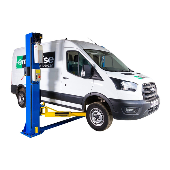
CHAIN-DRIVE TWO POST LIFT
Cargo Claims
If there is any missing or damaged
product during transportation, the
buyer must notate on the shipping
paperwork or refuse the shipment.
NOTATE ALL DAMAGE OR REFUSE
DAMAGED SHIPMENT!
Model: A255
△
DANGER
!
Read the entire contents of this manual before
using this product. Failure to follow instructions
and safety precautions could result in serious
injury or even death. Make sure all other
operators also read this manual. Keep this
manual near the machine so that it can be seen
by all users. By proceeding with installation and
operation, you agree that you are fully
understand the contents of this manual and take
full responsibility for the use of the product.
Original
Advertisement
Table of Contents

Related Manuals for AMGO A255


Summary of Contents for AMGO A255
- Page 1 Original CHAIN-DRIVE TWO POST LIFT Model: A255 △ DANGER Read the entire contents of this manual before using this product. Failure to follow instructions and safety precautions could result in serious Cargo Claims injury or even death. Make sure all other If there is any missing or damaged operators also read this manual.
-
Page 2: Table Of Contents
CONTENTS PROFILE ..................1 IMPORTANT SAFETY INSTRUCTIONS ..........3 I. PRODUCT FEATURES AND SPECIFICATIONS ........5 II. INSTALLATION REQUIREMENT ............. 7 III. INSTALLATION STEPS ............... 9 IV. EXPLODED VIEW ..............30 V. TEST RUN ................37 VI. OPERATION INSTRUCTIONS ............. 39 VII. MAINTENANCE SCHEDULE ............40 VIII. -
Page 3: Profile
PROFILE The two post lift is a commonly used vehicle repair and maintenance tool that uses a hydraulic system that can lift the car up to a certain height so that the vehicle can be placed in a suitable position for inspection and repair. Car lifts can be divided into pneumatic and electric, which have the characteristics of safe and reliable, simple structure and quick installation. - Page 4 SAFETY WARNING LABEL Fig.1...
-
Page 5: Important Safety Instructions
IMPORTANT SAFETY INSTRUCTIONS In order to properly maintain your product and ensure operator safety, it is the responsibility of the product owner to read and follow these instructions! 1. Ensure product installation complies with all applicable local regulations and rules, such as Occupational Safety and Health Administration regulations and electrical codes. - Page 6 proper lubrication and maintenance procedures according to the manual. Keep handles or buttons clean, dry, and free of oil. 17. Stay alert. Use common sense to observe what you are doing and stay alert. 18. Check for damaged parts. Check for adjustments to moving parts, damage to parts, or anything that may affect their operation.
-
Page 7: Product Features And Specifications
. Automatic arm restraints, with high-strength moon gear and arm lock; · Self- lubricating UHMW Polyethylene sliders and bronze bush; · Single-point safety release, and dual safety design; · ₵ 9.5 mm areo sync cables used for synchronization. MODEL A255 SPECIFICATION Max Lifting Height Max safety lock height Minimum... - Page 8 Arm Swings for Model A255 955-1820mm 2673/2810mm 3692/3829mm Fig. Car-in direction Fig. 4 △ CAUTION When driving the vehicle, stay in the middle between the columns. If you hit any part of the lift, you could damage the car or lift.
-
Page 9: Installation Requirement
II. INSTALLATION REQUIREMENT A. Tools Required Rotary Hammer Drill (Φ19) Carpenter’s ink marker Screw Sets Hammer Level Bar Tape Measure (7.5m) English Spanner (12") Pliers Ratchet Spanner with Socket (28 Socket Head Wrench (10#) Wrench set Lock Wrench ... - Page 10 Equipment storage and installation requirements. 1.Store the equipment in a dry, non-moldy, non-flammable environment; 2.The lift is only approved for indoor installation and use, and outdoor installation is prohibited; 3.When installing the device, take safety precautions according to the instructions to avoid device damage;...
-
Page 11: Installation Steps
Concrete intensity must be 3500psi (245Kg/cm ) minimum Fig.7 E. Power supply 1. You are required to use a licensed and qualified electrician for the installation process. mm² 2. The power supply capacity must be more than 3kw, with a cord larger than 2.5 and must be properly grounded. - Page 12 Installation ceiling height requirement: >3110mm 1500mm 3000mm 1500mm Car-in direction Fig.8 ⚠ CAUTION Installing the lift on a surface with slopes more than 3° could lead to injury or even death. PEAK lifts are designed for installation on a flat and level surface only. (Defined as no more than 10mm difference over the installation area ).
- Page 13 C. Check the parts before assembly. 1. Received lift and hydraulic power unit ( See Fig.10). Fig. 10 2. Move the lift aside with fork lift or hoist, and open the outer packing carefully, check all parts according to the shipment parts list. (See Fig.
- Page 14 5. Move aside all parts to installation site, and check according to the shipment parts list. (See Fig. 13, 14). Parts in the parts box (80) Parts in the shipment parts list Fig. 14 Fig. 13 6. Open the parts bag and check the parts according to parts bag list (See Fig.
- Page 15 . Parallelly lay down the two columns on the installation site, position the power-side column according to the actual installation site. Usually, it is suggested to install the power-side column on the front-right side from which vehicles are driven to the lift, then install the top plate (See Fig.16).
- Page 16 Erect the columns, install anchor bolts, check the columns plumbness with level bar, and adjust with shims if the columns are not vertical. Don’t tighten the anchor bolts at this time (See Fig. 17). Note: There are 2 width settings for installation, please choose according to your need.
- Page 17 2. Using the prescribed rotary hammer drill, and drill all the anchor holes and install the anchor bolts. Then tighten the anchor bolts. (See Fig.19) Note: Torque of anchors is 150N.m. Minimum embedment of anchors is 110mm. Fig. 19 △ CAUTION Concrete and anchor bolts must comply with above specifications.
- Page 18 H.Install sync cables Raise both sides of carriages and lock them to the same level. 1. Sync cable installation of narrow setting (width between columns: 3000mm). 1.1 Pass the cable from the bottom to the top of carriage, pull it out from the hole of carriage and then tighten the two cable nuts.
- Page 19 1.2 Illustration of sync cable connection. Fig. 23...
- Page 20 2. Sync cable installation of wide setting (Width between columns: 3137mm) 2.1 Pass the cable from the bottom to the top of carriage, pull it out from the hole of carriage and then tighten the two cable nuts. (See Fig.24) Tighten the two cable nuts Cable connecting...
- Page 21 2.2 Illustration of sync cable connection. Pass the cables through the holes Fig. 25...
- Page 22 I. Install lock release cable (See Fig. 26). Note: Install the lock release cable from the offside safety device, pay attention to the pass through direction. 1. Install the lock release cable from the offside safety device 2. Follow the arrow direction, pass through the cable from offside safety device to...
- Page 23 Install hydraulic power unit and oil hose assy. Tighten all hydraulic fittings after installation. (See Fig. 27) View A View B View Pass the oil hose through the strengthen board notch. 75/76 75/76 Fig. 27 For narrow setting (width between columns: 3000mm), use oil hose No.:76(L=1390mm). For wide setting (width between columns:3137mm ), use oil hose No.:75(L=1520mm).
- Page 24 Install circuit system 1. Install control box and high limit switch assy. Install high limit switch Fig. 28 2. Install motor wire: connect 4x2.5 black wire (91)to the motor. 2.1 Wires connection diagram for three phase motor. (See Fig. 28) Connect motor wires (M1,M2,M3) respectively to the three wires in the motor.
- Page 25 2.2 Wires connection for single phase motor Connect motor wires (M1, M2) respectively to the two wires in the motor M2 (Blue) M1 (Brown) Earth wire (Yellow green) Fig. 30 2.3 Install solenoid valve wires: connect 2*1 black wire (89) to the solenoid valve coil. High limit switch wire Solenoid valve...
- Page 26 3. Connect the high limit switch wire, motor wire and solenoid wire respectively to the control box. (See fig.32) Note: after installation, wrap the wires that exposed outside with winding tube Power supply Solenoid valve wire Motor wire High limit switch wire Fig.
- Page 27 4.2 Circuit schematic diagram. (See Fig. 34) Three phase Fig. 34 Parts list of circuit components: Item Name Code Specification Power switch 380V AC Breaker Breaker Breaker AC contactor 24VAC Hydraulic solenoid valve 24V AC Indicator lamp 24V (White) Push button Down Single Motor...
- Page 28 5. Wires connection and circuit diagram for single phase motor. 5.1 Wires connection diagram in the control box. (See Fig.35) Power Earth High limit Motor Solenoid valve wire wire switch wire wire wire Fig. 35 5.2 Circuit schematic diagram Fig. 36 Single phase Item Name...
- Page 29 △ DANGER All electrical wiring must be performed by a licensed and certified electrician. Before ensuring the main power has disconnected from the lift and cannot be re-applied until all procedures have been completed, don not perform any maintenance or installation to the lift.
- Page 30 Install floor cover and protection cover. (See Fig.38) Choose different floor cover according to installation width in Step E. NOTE: Wide setting (width 3137mm between columns ): Use wide extension cover (3) to connect the floor cover. M8*20 hex bolt with flat washer, lock washer and nut.
- Page 31 2. Lowing the carriages down to the lowest position, then use the 10 socket head wrench to loosen the socket bolt (See Fig. 40); follow the arrow direction to adjust the moon gear(See Fig. 41); lock the bolts after the moon gear and arm lock are engaged well(See Fig.
-
Page 32: Exploded View
IV. EXPLODED VIEW Car-in direction Fig. 37 Fig. 43... - Page 33 PARTS LIST Item Part# Description Qty. 11207001 Floor cover 11207002 Narrow extension cover 11207003 Wide extension cover 11217019 Top pulley 10217020 Bronze bush for pulley φ31*φ25.1*16 10209012 Snap pin φ3.2 10209056 Nylok nut M10 10209049 Plastic pulley (black) Hex bolt M8*20 (w/ flat washer, lock washer, hex 1004574011 nut ) 11207053...
- Page 34 Item Part# Description Qty. 11217037 Pin for bottom pulley 11217036 Bottom pulley 11207054 Off-side column 11207018 Off-side safety cover 1102504002 Extension adapter 3’’ 1102504001 Extension adapter 6’’ 1002735012 M8*16 hex bolt (w/ flat washer, lock washer) 11206154 Toe guard 10206156 Tool tray M12*30 hex bolt (w/ flat washer, lock washer, hex 1002205002...
- Page 35 Item Part# Description Qty. 10207500A Parts box M10*25 hex bolt (W/ flat washer, lock washer, hex 1003085008 nut) M6*12 round head bolt (w/ flat washer, lock 1002515001 washer) 10206220 Control box (single phase) 10206123 Control box (three phase) 10206013A Limit switch assy. (include wire L=1660) 10206013A Limit switch 10620059...
- Page 36 2. Exploded view of rubber pad assy. (10203054) Item Part# Description Qty. 10420043 M12*48 socket bolt 10203043 Rubber pad 11203026 Elastic retaining ring 10203041 Middle arm 11203025 Adjusting rod 10203042 Elastic retaining ring 11203024 Adjusting sleeve Fig. 45 3. Exploded view of chain pulley seat assy. (11207681): Fig.
- Page 37 4. Exploded view of the oil Cylinder (10207010) Fig. 47 Item Part# Description Qty. 11207027 Piston rod 11207028 Piston 10206069 O-ring 10620053 Support ring 10620054 Y-Ring 10630027 O-ring 10206071 Hex nut 10207029 Cylinder adjusting sleeve 10217078 Dust ring 10520058 O-ring 11207030 Head cap 10201034...
- Page 38 5. Exploded view of electric control box Control box: 10206220 (Single phase) 10206123 (Three phase) Fig. 48 Electric control box parts list Item Part# Description 10420069A Cover of Control Box 10201094 Indicating Lamp (24V White) 10420071 Button UP 10420072 Button DOWN 10420139 Screw 41010217...
-
Page 39: Test Run
6. Illustration of hydraulic valve for power unit Oil return port Relief valve Solenoid valve Oil Out let Throttle valve Check valve Fig. 49 V. TEST RUN 1. Adjustment of sync cable (See Fig. 50) Use wrench to hold the cable fitting, meanwhile using ratchet spanner to tighten the cable nut until the two sync cables are adjusted to a certain tension force and are consistent. - Page 40 3. Adjust the lowering speed If necessary, you can adjust the lower speed of the lift by turning the throttle valve clockwise to decrease it, or counterclockwise to increase the lower speed. Throttle valve Throttle valve Clockwise to decrease the lowering speed Counterclockwise to increase lowering speed.
-
Page 41: Operation Instructions
VI. OPERATION INSTRUCTIONS Please read the safety tips carefully before operating the lift To lift vehicle 1. Keep operation site clean; 2. Lower the lifting arm to the shortest position; 3. Retract the lifting arm to the shortest position; 4. Open lifting arms out to the sides; 5. -
Page 42: Maintenance Schedule
VII. MAINTENANCE SCHEDULE Monthly: 1. Tighten the anchor bolts with to 150 Nm torque force; 2. Check all fittings, bolts and pins to ensure proper connections; 3. Lubricate cable and slider with lubricant; 4. Make a visual inspection of all oil hoses/lines for possible wear or leakage; 5. -
Page 43: Trouble Shooting
VIII. TROUBLE SHOOTING TROUBLE CAUSE REMEDY 1.Start button does not work 1. Replace button 2. Wiring connections are not in good 2.Repair all wiring connections Motor does not condition 3. Motor burned out 3. Repair or replace motor 4. AC contactor in damage 4. -
Page 44: Car Lift Safety Tips
IX. CAR LIFT SAFETY TIPS Post these safety tips in a place where you can always alert the operator. Please reference to the lift manufacturer’s manual for specific information about the lift. 1. Check the lift daily. If the machine breaks down or has damaged parts, do not operate, and use the parts of original equipment to repair. - Page 45 PEAK CORPORATION No.3 Luomu Road,Shishan Town,Nanhai District,Foshan(528225),Guangdong,China Tel:86-757-81102815 81102805 Fax: 86-757-81102809 Email: amgo@peaklift.cn http://www.amgolift.com Manual Part No.: 72226313 Revision Date: 2023/10...
Need help?
Do you have a question about the A255 and is the answer not in the manual?
Questions and answers