Table of Contents
Advertisement
Quick Links
Advertisement
Table of Contents

Related Manuals for AMGO PRO-14


Summary of Contents for AMGO PRO-14
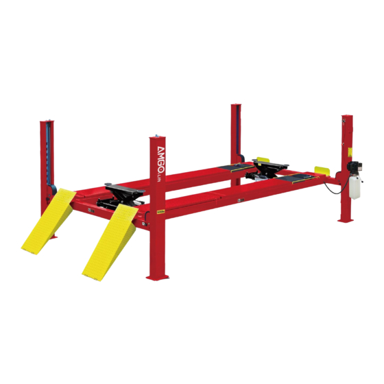
- Page 1 Original PRO-14A PRO-14.PRO-14E FOUR POST LIFT PRO-14AE PRO-14(A)...
-
Page 2: Table Of Contents
CONTENTS Product Features and Specifications ............. 1 Installation Requirement ..............2 Steps of Installation …................ 4 Exploded View ................. 23 Test Run ……….................. 32 Operation Instruction ............... 33 Maintenance ................... 33 Trouble Shooting ................34 Lift Disposal..................34... -
Page 3: Product Features And Specifications
I. PRODUCT FEATURES AND SPECIFICATIONS MODEL PRO-14(A) FEATURES · Manual control system. · Mechanical self-lock and air-drive safety release. · Electric hydraulic power system, cable-drive. · Strengthen and non-skid diamond platforms. · Multiple turnplate pockets fit with different wheel base. -
Page 4: Installation Requirement
MODEL SPECIFICATIONS Overall Width Liftin Length Betw Lifting Lifting Overall Model (Inc. Motor Capacity Height Width Time Ramps) Colu PRO-14 14000LBS 73-1/2” 257-1/2” 130-7/8” 116” 2.0HP PRO-14A 14000LBS 75-3/8” 257” 130-7/8” 116” 2.0HP PRO-14E 14000LBS 73-1/2” 130-7/8” 116” 2.0HP 286”... - Page 5 B. Equipment storage and installation requirements. The equipment should be stored or installed in a shady, normal temperature, ventilated and dry place. C. SPECIFICATIONS OF CONCRETE (See Fig. 5) Specifications of concrete must be adhered to the specification as following. Failure to do so may result in lift and/or vehicle falling.
-
Page 6: Steps Of Installation
III. STEPS OF INSTALLATION A. Location of Installation Check and insure the installation location (concrete, layout, space size etc.) is suitable for lift installation. B. Check the Parts Before Assembly 1, The equipment should be unload and transfer by forklift. (See Fig.6) Fig. - Page 7 5. Loose the screws of the upper package stand, take off the offside platform, take out the parts inside the power-side platform, than remove the package stand. 6. Move aside the parts and check the parts according to the shipment parts list (See Fig. 10,Fig.11). PRO-14,PRO-14E Fig.10...
- Page 8 6.2 PRO-14A, PRO-14AE Fig.11 7. Open the carton of parts and check the parts according to the parts box list (See Fig. 12) Fig. 12...
- Page 9 8. Check the parts of the parts bag according to the parts bag list (See Fig. 13) Parts bag 1 for PRO-14, PRO-14E Parts bag 1 for PRO-14A, PRO-14AE Parts bag (2) Fig.13...
- Page 10 Make sure the size is right and base is flat (see Fig. 14). Note: Reserve space front and behind the installation site. Car in Use a carpenter’s chalk line to establish Direction installation layout Fig. Model PRO-14,PRO-14A 216 1/2” 130 7/8” 253” PRO-14E、PRO-14AE 245” 130-7/8” 277-7/8”...
- Page 11 D. Install Cross Beams (See Fig. 15, Fig. 16) Hole towards inside Fig. Fig.
- Page 12 E. Fix the Anchor Bolts Spring washer 1. Prepare the Anchor Bolts (See Fig. 17). Washer Fig. 2. Using the prescribed rotary hammer drill, and drill all the anchor holes and install the anchor bolts, do not tighten the anchor bolts first (See Fig.
- Page 13 2. Install Safety Ladders (See Fig. 20). This height should be the same for four safety ladders Safety ladder pass through the hole of the top plate, then tighten the two nuts. Fig. G. Put the Cross Beams at the same height (See Fig.
- Page 14 H. Install power side platform. 1. Put the power side platform upon the cross beams by fork lift or manual, offset the cross beams to the outside till the pulleys of both platforms can set up into the cross beam , Install the power side platform and screw up the bolts.
- Page 15 I. Assembly offside platform and slider block. check the vertical of columns with level bar, adjusting with the shims if the columns are not vertical, and then tighten the anchor bolts (See Fig. 24). 3-15 3-16 Using the ratchet spanner with socket to tighten the bolts 3-14 Install the slider block...
- Page 16 J. Install cables (See Fig. 25). 1. Pass through the cables from the platform to the columns according to the number of the cables ○ ○ ○ ○ Cable Length PRO-14(A) 162-3/4” 438-1/2” 230-1/2” 371” (inc. connecting fitting) Length PRO-14E(AE) 191-3/8” 495-5/8”...
- Page 17 2. The cable pass through the cross beam to top plate of columns and be screwed with cable nuts (See Fig. 26). Cable pass through Cable pass through top between the big pulley plate and be screwed and tension pulley with cable nuts.
- Page 18 3. Illustration for platform cables (See Fig. 27). Limit block cable ② cable ④ cable ② cable ④ cable ③ cable ① cable ④ cable ③ cable ④ cable ② cable ② cable ① Limit slider cable ④ cable ② Hex Bolt M10*150 Fig.
- Page 19 K. Install Oil-water separator, Manual control air valve and Power unit (See Fig. 28). Air inlet Air outlet Air flow of oil water separator The ”P” side on air solenoid valve is for Air inlet Fig. Air flow of air solenoid valve Item Part# Description...
- Page 20 L. Install Hydraulic System (See Fig. 29). Note: Oil hoses connected to oil cylinder must be passed above the cable, cylinder inlet port must swing upward to avoid the oil hose and oil return pipe scratched by cable. Protective ring Oil hose and air line pass through the retainer...
- Page 21 M. Install air-line system 1. Connecting front and rear Cross Beam cylinders by using 6*4 black air line. (the actual length of air line can be cut by user) ( Fig.30 2. Cut the 6*4 black air line by scissor between two retainer, then connect the air line with T fitting.
- Page 22 5. Install oil-water separator and manual control air valve. (see Fig.33) Oil-water separator Connecting Oil-water separator and manual controlled air valve using black air line 8*6 Manual controlled air valve 6*4 black air line Fig. 6. Connecting air inlet (Air supply pressure 5kg/cm - 8kg/cm ), adjusting the air pressure of Oil-water separator to 0.8MPa...
- Page 23 N. Install Electrical System Connect the power source on the data plate of Motor. Note: 1. For the safety of operators, the power wiring must contact the floor well. 2. Pay attention to the direction of rotations when using 380V, three phase motors.
- Page 24 P. Install Drive-in ramp, Tire stop plate, Platform locking plates, Steel ball set (See Fig. 37) Install Drive-in Install Tire stop ramp plate Fig.37...
-
Page 25: Exploded View
IV. EXPLODED VIEW Model PRO-14, PRO-14E Fig.38... - Page 26 Model PRO-14A,PRO-14AE Optional turnplates Fig.39...
- Page 27 Parts list PRO- PRO- PRO- Item Part# Description PRO-14A 14AE 11460021 Power-side Column 11460020 Offside Column 10460063 Cross Beam assy. 10476016 Limit slider 10209059 Anchor Bolt 11460074 Safety Ladder 10476014 Hex Nut 11460054 11460024 Power-side Platform 11460024 11460055 11476010 Pulley Shaft Weldment 10476029 Washer for pulley 11476636...
- Page 28 10209010 Snap PRO- PRO- PRO- Item Part# Description PRO-14A 14AE 10420156 Protecting Rubber Ring 10420045 Washer 10420004 Pin for Drive-in Ramp 10420005 Fixing Bolt 10460501 Parts box 10470501 11420031-1 Tire Stop Plate 10201005 Split pin 10201090 Shim(1mm) 10620065 Shim(2mm) 10209056 Self locking nut 11420217 Cable Limit Pin...
- Page 29 10460092 10460013 Black Air Line PRO- PRO- PRO- Item Part# Description PRO-14A 14AE 10460094 Black Air Line 10420167A Black Air Line 11480033 Turnplate adjusting block 11480045 Turnplate adjusting block 11440082 Turnplate adjusting block 11476635 Pulley 10476024 Washer for Pulley 10476014 Hex nut 4.1 CROSS BEAM EXPLODED VIEW (10460063) Fig.
- Page 30 3-13 10420046 Split Pin 3-14 10420042 Plastic Slider Item Part# Description Note 3-15 10209033 Washer 3-16 10420043 Socket Bolt 3-17 10420175 Slack-cable safety lock (left & right ) Each 2 3-18 10420171 3-19 10420172 Pin Bush For Slack-cable safety lock 3-20 10206019 Snap Ring...
- Page 31 55-9 10460052 Y- Ring 55-10 11460053 Piston POWER UNIT EXPLODED VIEW(071102) 220V/60Hz Single Phase Fig.42...
- Page 32 Filter 81400290 81400413 Steel Motor Push button 10420070 AC connector 41030055 Motor terminal box cover 81400287 71111216 AMGO power unit label 81400560 Throttle valve 81400266 Relief valve 81400284 Inner hex iron plug 10720118 Hair pin 81400451 Release valve handle 10209020...
- Page 33 Illustration of hydraulic valve for power unit Oil return port Relief Release valve valve Check valve Throttle Oil outlet valve Handle for relief valve Fig.43...
-
Page 34: Test Run
V. TEST RUN 1. Fill the reservoir with approximately 14L Hydraulic Oil (Note: In consideration of Power Unit’s durability,please use Hydraulic Oil 46#). Press the push button , the Cables will be strained. Check whether the Cables match the Pulley. Make sure the Cables are not across. 3. -
Page 35: Operation Instruction
VI. OPERATION INSTRUCTIONS To lift vehicle 1. Keep clean of environment near the lift; 2. Drive vehicle to the Platform and put on the brake; 3. Turn on the power and press the push button, raise the lift to the working position; Note: make sure the vehicle is steady when the lift is raised. -
Page 36: Trouble Shooting
VIII. TROUBLE SHOOTING TROUBLE CAUSE REMEDY 1. Start Button does not work 1.Replace start button 2.Wiring connections are not in good 2.Repair all wiring connections condition Motor does 3. Motor burned out 3.Repair or replace motor not run 4. AC contactor burned out 4.Replace AC contactor 5. - Page 37 AMGO HYDRAULIC CORPORATION 1931 Jo Rogers Blvd, Manning, South Carolina, USA Tel: (803) 505-6410 Fax: (803) 505-6410 Manual Part No.: 72146007 Revision Date: 2020/01...
Need help?
Do you have a question about the PRO-14 and is the answer not in the manual?
Questions and answers