Table of Contents
Advertisement
Quick Links
Advertisement
Table of Contents

Related Manuals for AMGO A440-HP


Summary of Contents for AMGO A440-HP
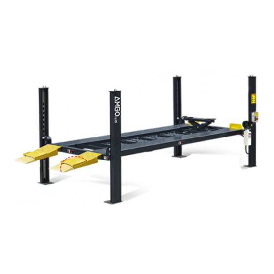
- Page 1 Original FOUR-POST PARKING LIFT Model: A440-HP Fig. 1...
-
Page 2: Table Of Contents
CONTENTS Product Features and Specifications ............. 1 Installation Requirement ..............2 Steps of Installation ................4 Exploded View ..................28 Test Run ..................38 Operation Instruction ................39 Maintenance ..................40 Trouble Shooting ................41 Lift Disposal ..................41... -
Page 3: Product Features And Specifications
I. PRODUCT FEATURES AND SPECIFICATIONS 4-POST MODEL A440-HP FEATURES · Single point manual safety release. · Four mechanical locking devices, each equipped with both primary and secondly safety locks. · Power-side column can be installed at both side, front or rear. -
Page 4: Installation Requirement
II. INSTALLATION REQUIREMENT A. TOOLS REQUIRED Tape Measure (7.5m) Carpenter’s Chalk Screw Sets Hammer Level Bar Pliers English Spanner (12") Lock Wrench Wrench set Socket Head Wrench , 13 , 14 , 15 , 17 , 19... - Page 5 B. Equipment storage and installation requirements. The equipment should be stored or installed in a shady, normal temperature, ventilated and dry place. C. The equipment should be unloaded and transferred by forklift. Fig.3 D. SPECIFICATIONS OF CONCRETE (See Fig. 4) Specifications of concrete must be adhered to the specification as following.
-
Page 6: Steps Of Installation
III. STEPS OF INSTALLATION A. Check the parts before assembly 1. Packaged lift and Hydraulic Power Unit (See Fig. 5). Fig. 5 2. Open the outer packing carefully, check the parts according to the shipment list. (See Fig. 6). Power-side Cross Column Offside... - Page 7 5. Move aside the parts and check the parts according to the shipment parts list. (See Fig. 8). Fig. 8 6. Open the carton of parts and check the parts according to the parts box list (See Fig.9). Fig. 9...
- Page 8 Make sure the size is right and base is flat (see Fig. 11). Note: Reserve appropriate space in front and behind the installation site Use a carpenter’s chalk line to establish installation layout Fig. 11 MODEL A440-HP 5115mm 3106mm 5984mm...
- Page 9 C. Install cross beams (See Fig.12, Fig.13). Note: Pay attention that the cross beams’ slots should be positioned towards inward the platform and the safety lock connecting assy. should be adjacent to the power unit column. The power-side column need to be installed according to the installed position of the safety lock release handle.
- Page 10 D. Install the Safety Ladders. 1. Take off the pulley safety cover and unscrew the four upper nuts of the safety ladders, and then adjust the four lower nuts so they are at the same position, then insert the safety ladder (See Fig.
- Page 11 2. Install Safety Ladders (See Fig. 15). This height for four threaded rod of safety ladders should be the same. Safety ladder across the hole of the top plate, then tighten the two nuts Fig. 15 E. Put the cross beams at the same height and lock on the safety ladder (See Fig.
- Page 12 F. Install power-side platform. Raise the power-side platform above the cross beam by a forklift or crane. Then move the cross beam outwards until the pulleys of both platforms can be rested into the cross beams’ slots ( see Fig.17 ). Tighten the power-side platform to the cross beams by using bolts.
- Page 13 2. Install the tire stop plate and connecting bolts: Tighten the platform and the cross beam B with bolts. Tighten the tire stop plate , platform and cross beam A with bolt. Note: Install the tire stop plate on the front of platform. And the bolts for connecting with tire stop plate is longer, pay attention when choosing the bolts.
- Page 14 G. Install the offside platform and limit slider, and platform strengthen bolts. Check the verticality of columns with level bar and adjust with shims. (See Fig. 19) Install the platform strengthen bolts. Level bar Position the sliders along the bent edges of the columns. Connect the slide blocks to the cross beam with bolts.
- Page 15 (See Fig. 20) Install the cylinder connecting plate as shown and pay attention to the direction of unfilled corner on the plate. Cable installation diagram Fig. 20 ○ ○ ○ ○ Cable Length for A440-HP 3400mm 9875mm 4980mm 8250mm (inc. connecting fitting)
- Page 16 2. The cable goes through the cross beam to top plate of columns and tighten with cable nuts (See Fig. 21). Cable goes between the Cable pass through top big pulley and tension plate and tighten with pulley cable nuts. Fig.
- Page 17 3. Illustration for platform cables (See Fig. 22). ○ Cable ○ Cable ○ ○ Cable Cable ○ Cable ○ Cable ○ Cable ○ Cable ○ Cable ○ Cable ○ Cable ○ Cable ○ Cable ○ Cable Socket Bolt M10*120 Fig. 22...
- Page 18 I. Install safety device control handle (See Fig. 23) Note : The safety release handle should be installed adjacent to power unit. Cross beam B View B Cross beam A Fig. 23 Connecting bar View A Safety lock rotating Connecting bar device Pass the connecting bar through middle of safety lock rotating...
- Page 19 J. Install power unit and connection tube. Note: Power unit must be installed near the safety release handle 1. When install Power unit on the cross beam A , the installation of Connection tube is as Fig.24 Cross beam A Cross beam B Car in direction...
- Page 20 K. Install Hydraulic System 1. For power unit attached to the column of cross beam A (See Fig. 25) Note: Oil hoses connected to oil cylinder must be passed above the cable to avoid the oil hose scratched by cable. Oil return hose Oil inlet port inclined Retaine...
- Page 21 L. Install control box and limit switch.(Fig. 26) Install high limit switch Install lower alarm limit switch Slider Cross beam 520m Note: When the cross beam rise to the highest place, the lift will stop while the slider touch the high limit switch control bar; while the lift lower to 520mm from ground, the lift will stop while the lower alarm limit switch touch the limit switch control bar.
- Page 22 Instruction of limit switch wire connection 90º 1. Wire connecting for high limit switch. Connecting 11 & 12 (NC) of limit switch to terminals 3 & 5 control box 90º Wire connecting for low limit switch wire. Connecting 11 & 12 (NC) of limit switch to terminals 1 &...
- Page 23 M. Install Electrical System 1. Connecting wire with control box (See Fig. 27) Note: 1) Specification of wire of limit switch and Air solenoid valve is 2×1 2) Wire cable for power source and motor are 4×2.5 3) Using white bobbin to wind around wire. 4)Fix the wire of limit switch in the column with retainer, tie the wire with the protecting plastic hose by the cable ties.
- Page 24 2. 380V Wire connection and circuit diagram 2.1 Wire connection diagram in the control box (See Fig. 28) Lower Wire of Power High Wire of Earth limit solenoid limit wire motor wire switch valve switch Fig. 28 2.2 380V Wire connection diagram of hydraulic motor (See Fig.
- Page 25 380V Circuit component Item Name Code Specification Item Name Code Specification Lowering Power switch 380V AC Pass Duplex alarm button Breaker Motor 3 phase Breaker Transformer 24V AC High limit Breaker switch Low limit AC contactor 24V AC switch Hydraulic solenoid 24V AC Buzzer...
- Page 26 3.3 220V Circuit diagram (See Fig. 33) Single phase Fig. 33 220V Circuit component Item Name Code Specification Item Name Code Specification Lowering alarm Power switch 380V AC Pass Duplex button Breaker Motor 3 phase Breaker Transformer 24V AC High limit Breaker switch AC contactor...
- Page 27 O. Install drive-in ramp, jack tray and plastic oil pans (See Fig. 35). According to the below diagram screw up the M16*30 bolts, then attach the drive-in ramp. 76(Optional) 76A(Optional) Screw M16*30 bolts to the side hole on the cross beam Attach the drive-in ramp with the hex bolts Fig.
- Page 28 Q. For optional kits installation. 1. Install optional caster kits or Jack (See Fig. 37) 78-2 78-1 78-3 78-4 78-5 78-6 78-7 78-8 Fig. 37 R. Fix the anchor bolts 1. Prepare the anchor bolts (See Fig. 38). Washer Lock washer Fig.
- Page 29 2. Using the prescribed rotary hammer drill, and drill all the anchor holes and install the anchor bolts. Do not tighten the anchor bolts (See Fig. 39). Note: The tightening torque for the anchor bolt is 150N.m , Tap anchor bolts into the anchor hole at least 90mm deep.
-
Page 30: Exploded View
IV. EXPLODED VIEW Model A440-P A440-HP Fig. 40... - Page 31 PARTS LIST Item Part# Description Qty. Note 11410111-01 Power-side Column 11410075-01 Offside Column 11410050 Cross Beam A 11410076-01 Off-side Platform 11410077A-01 Power-side Platform 11410053 Cross Beam B 1104233003C Folding drive-in ramp 10209043 Hex Bolt M8*20 10209033 Washer φ8 10209005 Nylok Nut M8 10217002 Hex nut M8 11410090...
- Page 32 Item Part# Description QTY. Note Cable ② φ9.52*9725mm 10410172-01 10410170-01 Cable φ9.52*4945mm 10410169-01 Cable ④ φ9.52*8160mm Socket Bolt M10*120 10600015 11410069-01 Connecting bar for safety device 11410024 Connecting tube 10209032 Socket bolt M8*25 10217005 Plastic ball M10 10209056 Nylok Nut M10 10410025 Socket bolt M8*35 11410026...
- Page 33 Item Part# Description QTY. Note 10217135 Wire for motor 4*2.5²*900mm 10410107 Wire for hydraulic solenoid valve Optional kits 11410062 Jack tray 10410095 Oil tray 96600005 Rolling jack 1040801 Caster kits 1140802 Motor fixing bracket Optional carters kits 78-1 11410042A Caster kits 78-2 10209125 Hex bolt M10*30...
- Page 34 4.1 CROSS BEAM Fig.41 Item Part# Description QTY. Note 10206032 Snap ring φ25 10410099 Spring φ14*φ2.5*100 11410063-01 Connecting bar for safety lock 11045720003A Safety lock rotated device 11410064-01 Connecting bar for safety lock 11420041A Pulley Pin 10420132A Bronze Bush φ41.3*φ35.1*20 3-10 11420040A Pulley pin sleeve...
- Page 35 4.2 Control box 10410114 Three Phase 10410178 Single phase Fig.42 Item Part# Description QTY. Note 67-1 10420069A Cover Of Control Box 67-2 10201094 Power Indicator 67-3 10420070 Button UP 67-4 10420070 Button Down 67-5 10420139 Screw 67-6 41010217 Power Switch (QSI) 10202047 Breaker 3P (3 Phase) 67-7...
- Page 36 4.3 CYLINDERS Fig. 43 Item Part# Description Qty. Note 12-1 10420059 Dust Ring 12-2 10420060 Y- Ring 12-3 11410082 Head Cap 12-4 10410083 O- Ring 12-5 11410078-01 Bore Weldment 12-6 11410079-01 Piston Rod 12-7 11410085 12-8 10410086 Support Ring 12-9 10410087 Y- Ring 12-10...
- Page 37 4.4 AMGO ELECTRIC POWER UNIT (81523001/81523002) 220V/50HZ, 1 Phase 380V/50HZ, 3 phase Fig. 44...
- Page 38 81400365 O Ring 10209152 Ties 85090167 Magnet 81400290 Filter net 81400590 Motor 81400208 Cover of Motor Terminal Box 71111190 AMGO Nameplate 81400560 Throttle valve 81400266 Relief Valve 81400284 Iron plug 81400420 Solenoid valve coil 81400423 Release valve(electrical) 81400566 Check valve...
- Page 39 380V/50Hz /3 Phase Electric Power Unit Parts list Item Part# Description Qty. Note AMGO Name Plate 71111191 Cup Head Bolt 81400300 Motor Connecting Shaft 81400363 81400362 Manifold Block 10209149 Spring Washer 81400276 Iron Plug 81400259 Red Rubber Plug 85090142 Socket Bolt...
-
Page 40: Test Run
Illustration of hydraulic valve for hydraulic power unit return Relief valve port Solenoid valve Oil outlet Throttle valve Check valve Fig. 45 V. TEST RUN 1. Fill the reservoir with approximately 11L Hydraulic Oil (Note: In consideration of Power Unit’s durability, please use Hydraulic Oil 46#). 2. -
Page 41: Operation Instruction
Diagram of Hydraulic System 1. Filter 2. Gear pump 3. Check valve 4. Relief Valve 5. Motor 6. Throttle Valve 7. Solenoid Valve 8. Cylinder For Four-post lift Fig. 46 VI. OPERATION INSTRUCTIONS To lift vehicle 1. Keep clean of environment near the lift. 2. -
Page 42: Maintenance
ALARM POWER INDICATOR POWER SWITCH DOWN PASS Fig. 47 VII. MAINTENANCE SCHEDULE Monthly: 1. Lubricate cable with lubricant; 2. Check all cable connection, bolts and pins to insure proper mounting; 3. Make a visual inspection of all hydraulic hoses/lines for possible wear or leakage; 4. -
Page 43: Trouble Shooting
3. Make at least one full trip raising and lowering per day. For exhausting the air from the system, which could effectively avoid the corrosion of the cylinder and damage to the seals caused by presence of air or water in the system. 4. - Page 44 PEAK CORPORATION No. 3 Luomu Road,Shishan Town,Nanhai District,Foshan(528225),Guangdong,China Tel:86-757-81102815 81102805 Fax: 86-757-81102809 Email:peak@peaklift.cn http://www.peaklift.cn Manual Part No.: 72213205 Revision Date: 2023/02...
Need help?
Do you have a question about the A440-HP and is the answer not in the manual?
Questions and answers