AMGO 408-P Installation And Service Manual
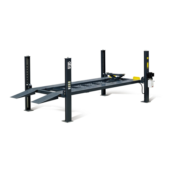
Four-post lift
Hide thumbs
Also See for 408-P:
- Installation and service manual (37 pages) ,
- Installation and service manual (42 pages)
Table of Contents
Advertisement
Quick Links
Advertisement
Table of Contents

Related Manuals for AMGO 408-P


Summary of Contents for AMGO 408-P
-
Page 2: Table Of Contents
CONTENTS Product Features and Specifications ............1 Installation Requirement ……………………………………………………………………………….2 Steps of Installation ….................3 Exploded View ..................23 Test Run ………..................26 Operation Instruction .................28 Maintenance ..................28 Trouble Shooting ................29 Parts List ..................30... -
Page 3: Product Features And Specifications
I. PRODUCT FEATURES AND SPECIFICATIONS 4-POST MODEL 408-P FEATURES · Single point manual safety release. · Four mechanical locking devices, each equipped with both primary and secondly safety locks. · Powerside column can be installed at both side, front or rear. -
Page 4: Installation Requirement
II. INSTALLATION REQUIREMENT A. TOOLS REQUIRED Tape Measure (295-1/4”) Carpenter’s Chalk Hammer Screw Sets Level Bar Pliers English Spanner (12") Lock Wrench Socket Head Wrench Wrench set , 13 , 14 , 15 , 17 , 19... -
Page 5: Steps Of Installation
B. SPECIFICATIONS OF CONCRETE (See Fig. 3) Specifications of concrete must be adhered to the specification as following. Failure to do so may result in lift and/or vehicle falling. 1. Concrete must be thickness 4” minimum and without reinforcing steel bars, and must be dried completely before the installation. - Page 6 2. Open the outer packing carefully, check the parts according to the shipment list. (See Fig. 5) Powerside Cross Column Offside Parts box Drive-in Platform Beam Platform Ramp Shipment Parts List Fig. 5 3. Take off the drive-thru ramps and columns (See Fig.6) Fig.
- Page 7 6. Open the carton of parts and check the parts according to the parts box list (See Fig. 8) Fig. 8 7. Check the parts of the parts bag according to the parts bag list (See Fig. 9) Fig. 9 B.
- Page 8 MODEL 408-P 173-1/4” 109-5/8” 205” C. Install cross beams (See Fig.11, Fig.12) The powerside column need to be installed according to the installed position of the safety lock release handle. Hole towards inside Fig. 11 Fig. 12...
- Page 9 D. Install the Safety Ladders. 1. Take off the pulley safety cover and unscrew a nut of the safety ladders, and then adjust the four lower nuts to be at the same position. Then install the safety ladder (See Fig. 13). Unscrew A nut of the safety ladders Limited Pin...
- Page 10 E. Put the cross beams at the same height and lock on the safety ladder (See Fig. 15). The safety device on the cross beam should lock into the safety ladders at the same level Lifting both cross beams to the same height. Lifting both cross beams to the same height, it is recommended to about 40”...
- Page 11 F. Install power side platform. 1. Install the power side platform on the cross beams by a fork lift or manual, offset the cross beams to the outside till the pulleys of both platforms can rest into the cross beams’ slots , Install the power side platform and screw up the bolts.
- Page 12 2. Install tire stop plate with bolts and washer on the platform: Tighten the platform on cross beam B with bolts, tighten the tire stop plate on cross beam A with bolts Note: The bolts for the side with tire stop plate is longer, pay attention when choosing the bolts (See Fig.17) Instruction: 1).
- Page 13 G. Install offside platform and plastic block, then install the bolts for the platform strengthen plate, check the plumbness of columns with level and adjusting with the shims (See Fig. 18). Install the bolts for the platform strengthen plate Level bar Position the slide blocks along the bent edges of the columns.
- Page 14 H. Illustration for cable installation 1. Pass through the cables from the platform to the columns according to the number of the cables (See Fig. 19) ① ② ③ ④ Cable 115-3/4” 336” 171-1/4” 280-3/8” Length (inc. fitting) (2940mm) (8535mm) (4350mm) (7120mm) Install the cylinder...
- Page 15 2. The cable goes through the cross beam to top plate of columns and be screwed with cable nuts (See Fig. 20). Cable goes between the Cable pass through top big pulley and tension plate and be screwed pulley with cable nuts. Fig.
- Page 16 3. Illustration for platform cables (See Fig. 21). Limit slider ○ Cable ○ Cable ○ ○ Cable Cable ○ ○ Cable Cable ○ Cable ○ Cable ○ Cable ○ Cable ○ Cable ○ Cable ○ Cable ○ Cable Hex Bolt M10*120 Fig.
- Page 17 I. Install release handle assy. See Fig.22 Noted: Power unit must be installed near the safety release handle. Cross beam B View B Cross beam A Fig. 22 View A Safety lock Safety lock rotated connecting assy. Safety lock device assy. connecting bar According to the above diagram, fix lock release Pass through the connecting bar...
- Page 18 J. Install power unit and connecting tube (See Fig. 23) Noted: Power unit must be installed near the safety release handle. 1. Install Power unit on the cross beam A Drive- in direction Cross beam B Cross beam A Fig. 23 View A Fixing plate Connecting tube pass...
- Page 19 Install Power unit on the cross beam B (See Fig. 24) Cross beam B Fig. 24 Car-in direction Fixing plate Connecting tube pass through the fixing plate Fix the connecting tube and the connecting bar for safety device by M8*25″ socket bolts...
- Page 20 K. Install Hydraulic System 1. For power unit attached to the column of cross beam A (See Fig. 25) Note: Oil hoses connected to oil cylinder must be passed above the cable to avoid the oil hose scratched by cable. Oil return hose Oil hose passed Retaine...
- Page 21 For power unit attached to the column of cross beam B (See Fig. 26) Note: The oil return hose can be adjusted when installation c、d Fig. 26 L. Install Electrical System Connect the power source on the data plate of Power Unit. Note: For the safety of operators, the power wiring must contact the floor well.
- Page 22 M. Install spring and safety cover of cross beam (See Fig. 28). Fig. 28 N. Install drive-in ramp, optional jack tray and optional plastic oil pans (See Fig. According to the below diagram screw up the M16*30″ bolts, then attach the drive-in ramp.
- Page 23 O. Install Rear wheel stop plates (See Fig. 30) After driving the vehicle on the lift, take off the drive-in ramp, install rear wheel stop plates to the drive-in ramp position. Fig. 30 For optional kits installation. 1. Install optional caster kits (See Fig.
- Page 24 2. Install optional motor fixing bracket (See Fig. 32, Fig.33). Motor fixing bracket on cross beam A Motor fixing bracket on cross beam B Fig. 32 Fig. 33 P. Fix the anchor bolts 1. Prepare the anchor bolts (See Fig. 34). Spring washer Washer Fig.
-
Page 25: Exploded View
IV. EXPLODED VIEW Model 408-P Fig. 36... - Page 26 CROSS BEAM Fig.37 CYLINDERS Fig. 38 Fig.38...
- Page 27 Manual power unit 110V/60HZ, Single phase Fig. 42 Fig. 39...
-
Page 28: Test Run
Illustration of hydraulic valve for AMGO hydraulic power unit Relief valve Oil return port Release valve Throttle Check valve valve Outlet Handle for Release valve Fig. 40 V. TEST RUN 1. Fill the reservoir with Hydraulic Oil (Note: In consideration of Power Unit’s durability,please use Hydraulic Oil 46#). - Page 29 6. After finishing the above adjustment, test running the lift with load. Run the lift with platforms in low position first, make sure the platforms can rise and lower synchronously and the safety device can lock and release synchronously. And then test run the lift to the top completely.
-
Page 30: Operation Instruction
VI. OPERATION INSTRUCTIONS To lift vehicle 1. Keep clean of environment near the lift. 2. Drive vehicle to the platform and put on the brake. 3. Take off the drive-in ramp, install rear wheel stop plates to the drive-in ramp position. -
Page 31: Trouble Shooting
VIII. TROUBLE SHOOTING TROUBLE CAUSE REMEDY 1. Button does not work 1.Replace button 2.Wiring connections are not in good 2.Repair all wiring connections Motor does condition not run 3. Motor burned out 3.Repair or replace motor 4. AC contactor burned out 4.Replace AC contactor 1.Motor runs in reverse rotation 1.Reverse two power wire... -
Page 32: Parts List
IX. PARTS LIST FOR MODEL 408-P Item Part# Description QTY. Note 410001 Powerside Column 410002 Offside Column 410003 Cross Beam A 410004 Offside Platform 410005 Powerside Platform 410006 Cross Beam B 410007 Drive-in ramp 209043 Hex Bolt 209033 Washer 209005... - Page 33 Item Part# Description QTY. Note 410024 Connecting tube 209032 Socket bolt 217005 Plastic ball 209056 Self locking Nut 410025 Socket bolt 410026 Safety release handle 410100 Extension lock release handle assy 209004 Rubber ring 209003 Hex Bolt 420166 Fitting 420119 Straight Fitting for cylinder 410135 Limit block...
- Page 34 Parts For Cross Beam 206024 Hex bolt 206032 Snap ring Bronze bush 3-2A 217020 410099 Spring 410031 Connecting bar for safety lock 206023 Self locking Nut 410032 Safety lock rotated device assy. 410033 Connecting bar assy. for safety lock 420041A Pulley Pin 420132A Pulley Bush...
- Page 35 81400362 Manifold Block 10209149 Lock Washer 81400276 Plug 81400259 Plug 85090142 Socket Bolt 81400312 Gear pump 81400294 Buffering Valve 10209034 Lock Washer 81400295 Socket Bolt 81400365 O Ring 10209152 Belt 85090167 Magnet 81400290 Filter 81400412 Motor 81400086 Running capacitor 10420070 Push Button 41030055 AC Contactor...
- Page 36 AMGO HYDRAULIC CORPORATION 1931 Jo Rogers Blvd, Manning, South Carolina, Zip:29102 Tel: (803) 505-6410 72103104 fax: (803) 505-6410 12/2015 Manual Part NO.: 72127501 Revision Date: 2017/07...
Need help?
Do you have a question about the 408-P and is the answer not in the manual?
Questions and answers