Table of Contents
Advertisement
Quick Links
Advertisement
Table of Contents

Related Manuals for AMGO A430-HP


Summary of Contents for AMGO A430-HP
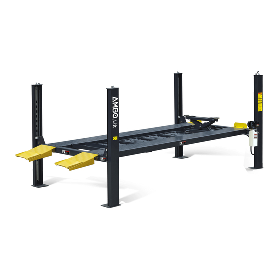
- Page 1 Original FOUR-POST PARKING LIFT Model: A430-HP Fig. 1...
-
Page 2: Table Of Contents
CONTENTS I. Product Features and Specifications………….………………………..………… 1 II. Installation Requirement ……….……….……….…………………..………………. 2 III. Steps of Installation……………………….………….....….………….4 IV. Exploded View………………………….…………………...……...…...……...…...…28 V. Test Run………………………...………………………….…………………………………37 VI. Operation Instruction……………………….……..……………………………………38 VII. Maintenance…………………….…………..……………………..…………………….39 VIII. Trouble Shooting………………….………………..………..…………..………..…40 IX. Lift Disposal ..............………..……..40... -
Page 3: Product Features And Specifications
I. PRODUCT FEATURES AND SPECIFICATIONS 4-POST MODEL A430-HP FEATURES ingle point manual safety release. ● S Four mechanical locking devices, each equipped with both primary ● and secondly safety locks. Power-side column can be installed at both side, front or rear. -
Page 4: Installation Requirement
II. INSTALLATION REQUIREMENT TOOLS REQUIRED Tape Measure Carpenter’s Chalk (7.5m ) Hammer Screw Sets Level Bar Pliers English Spanner (12") Lock Wrench Wrench set # # # # # :(12 、13 、14 、15 、17 、19... - Page 5 B. Equipment storage and installation requirements. The equipment should be stored or installed in a shady, normal temperature, ventilated and dry place. C. The equipment should be unload and transfer by forklift. Fig.3 D. SPECIFICATIONS OF CONCRETE (See Fig. 4) Specifications of concrete must be adhered to the specification as following.
-
Page 6: Steps Of Installation
III. STEPS OF INSTALLATION A. Check the parts before assembly 1. Packaged lift and Hydraulic Power Unit (See Fig. 5) Fig.5 (Optional) Plastic oil tray 2. Open the outer packing carefully, check the parts according to the shipment list. (See Fig. Parts Power-side Offside... - Page 7 5. Move aside the parts and check the parts according to the shipment parts list (See Fig. 8). Fig.8 6. Open the carton of parts and check the parts according to the parts box list (See Fig. 9) Fig.9...
- Page 8 B. Use a carpenter’s chalk line to establish installation layout as per Table 1 Make sure the size is right and base is flat (see Fig. 11). Note: Reserve appropriate space in front and behind the installation site. carpenter’s chalk line establish installation layout Fig.11 MODEL A430-HP 4164mm 2409mm 4811mm...
- Page 9 C. Install cross beams (See Fig.12, Fig.13) Note: Pay attention that the cross beam's slot should be positioned towards inward and the safety locks connecting assy. should be adjacent to the power unit column. power-side column need installed according to the installed position of the safety lock release handle.
- Page 10 D. Install the Safety Ladders. 1. Take off the pulley safety cover and unscrew the four upper nuts of the safety ladders, and adjust the four lower nuts so they are at the same position. Then insert the safety ladder (See Fig.
- Page 11 2. Install Safety Ladders (See Fig. 15) This height for four threaded rod of safety ladders should be the same. Safety ladder pass through the hole of the top plate, then tighten the two nuts Fig.15 E. Raise the cross beams at the same height and lock them on the safety ladders (See Fig.
- Page 12 F. Install power-side platform. 1. Raise the power-side platform above the cross beam by a forklift or crane. Then move the cross beam outwards until the pulleys of both platforms can be rested into the cross beams’ slots ( see Fig.17 ). Tighten the Power-side Platform to the Cross beams by using bolts. Offset the cross beam lean outward when putting the power-side platform on the...
- Page 13 2. Install the tire stop plate and connecting bolts: Tighten the platform and the cross beam B with bolts. Tighten the tire stop plate , platform and cross beam A with bolt. Note: Install the tire stop plate on the drive- in position . And the bolts for connecting with tire stop plate is longer, pay attention when choosing the bolts.
- Page 14 Install the offside platform and limit slide block, and platform strengthen bolts. Check the verticality of columns with level bar and adjust with shims. (See Fig. 19) Install the platform strengthen bolts. Level bar Slip the limit slide block with groove into the clearance along the bent edge of column.
- Page 15 H. Illustration for cable installation 1. Route the cable from the power-side platform via the pulleys according to the number below and then connect them to the columns. (See Fig. 20) Cable installation Instruction Fig.20 ○ ○ ○ ○ Cable Length 4595mm 10156mm...
- Page 16 2. The cable goes through the cross beam to column top plates and tightened with cable nuts (See Fig. 21) Cable goes through top plate and tightened with cable nuts. Cable goes through the cross beam pulley and tension pulley.The cable adjustment sleeve (17B) need not be installed for the first use.
- Page 17 3. Illustration for cables under platform . (See Fig. 22) Cable③ Cable ④ Cable ④ Cable ② Cable② Cable ① ○ Cable ○ Cable ○ Cable Socket Bolt M10*90 Cable ① Fig.22 ○ Cable ○ Cable...
- Page 18 I. Install release handle assy. (See Fig. 23) Noted: Power unit must be installed near the safety release handle. Cross beam B View B Cross beam A Fig. 23 Safety lock View A Safety lock connecting bar Safety lock rotated connecting assy.
- Page 19 J. Install power unit and connecting tube (See Fig. 24) Noted: Power unit must be installed near the safety release handle. 1.Install Power unit on the cross beam A Cross beam A Cross beam B Drive- in direction Fix the connecting tube and the connecting Fig.
- Page 20 K. Install Hydraulic System 1. For power unit attached to the power-side column for cross beam A (See Fig. 25) Note: Oil hoses connected to oil cylinder must be passed above the cable and oil inlet port should be inclined upwards to avoid the oil hose scratched by cable. Retaine Oil return Oil return hose passed...
- Page 21 L. Install the control box and limit switch( See. Fig.26) Install high limit switch Install low limit switch Slider Cross beam 520m Note: When the cross beam goes to highest place, the cross beam slider touched the high limit switch drive bar and the lift stop rising. When the cross beam lower to 520mm from ground, the cross beam slider touched the low limit switch drive bar and the lift stop lowering.
- Page 22 1. Wire connecting for high limit switch 90º Connecting 11 #& 12# (NC) of limit switch to terminals 3# & 5# of control 2. Wire connecting for low limit switch wire 90º Connect limit switch & 12 terminal to control box 1 &...
- Page 23 M. Install electrical system 1. Connecting wire with control box. ( See. Fig.27) Note: 1) Specification of wire of limit switch and Air solenoid valve is Specification of power source wire and motor wire : 4*2.5 2) Using white bobbin to wind around wire. 3) Fix the cable of limit switch on the column with retainer, tie the wire with protective hose by the cable ties.
- Page 24 380V Wire connection and circuit diagram 2.1 Wire connection diagram in the control box (See Fig. 28) Motor Wire of Wire Earth wire Power wire Wire of wire High Lowe Solenoid limit valve limit switch switch Fig.28 2.2 Wire connection diagram of Three phase hydraulic motor (See Fig.
- Page 25 380V Circuit component Item Name Code Specification Item Name Code Specification Lowering Power switch 380V AC Pass Duplex alarm button Breaker Motor 3 phase Breaker Transformer 24V AC High limit Breaker switch Low limit AC contactor 24V AC switch Hydraulic solenoid 24V AC Buzzer...
- Page 26 3.3 220V Circuit diagram (See Fig. 33) Single phase Fig.33 220V Circuit component Item Name Code Specification Item Name Code Specification Lowering alarm Power switch 380V AC Pass Duplex button Breaker Motor 3 phase Breaker Transformer 24V AC High limit Breaker switch AC contactor...
- Page 27 O. Install folding ramp assy. , optional jack tray and optional plastic oil tray (See Fig. 35) According to the below diagram screw the M16*30 bolts, then attach the folding ramp. 72(Optional) 76(Optional) Screw the M16*30 bolts to the side hole of the cross beam Fig.
- Page 28 Q. For optional kits installation 1. Install optional caster kits or jack (See Fig. 37) 73-2 73-1 73-3 73-4 73-5 73-6 73-7 73-8 Fig.37 Past list Item Part# Description QTY. Note 73-1 11410042A Caster kits 73-2 10209125 Hex bolt M10*30 73-3 10209039 Lock washerφ10...
- Page 29 R. Fix the anchor bolts 1. Prepare the anchor bolts (See Fig. 38) washer Spring Washer Fig.38 Adjust the column with the leveling bar and leveling pad , drill the anchor hole and install the anchor bolts. Tap the anchor bolts into the anchor hole with a hammer and tighten the bolts.( See Fig.39) Note: The tightening torque for the anchor bolt is 150N.m.
-
Page 30: Exploded View
IV. EXPLODED VIEW Fig.44 Fig.40... - Page 31 Fig.41...
- Page 32 PARTS LIST FOR MODEL A430-HP Item Part# Description QTY. Note 11410075 Offside Column 11410074 Power-side Column 1104542001B Cross Beam A 1104553001B Offside Platform 1104553001A Power-side Platform 1104542001B Cross Beam B 1104543020C Folding ramp 10201002 Hex Bolt M8*16 10209033 Washer φ8...
- Page 33 Item Part# Description QTY. Note 11410026 Safety release handle 11410100 Extension lock release handle 1004554006 Handle rope 10209004 Rubber ring φ8*φ20*3 10209003 Hex Bolt M8*25 10209043 Hex Bolt M8*20 10217002 Hex nut M8 10420166 Screw joint fitting 11420243 Straight Fitting 3/8NPT(M)*G3/8(M) 11420245 Straight Fitting G3/8(F)*3/8NPT(F) 11209119...
- Page 34 Control box (Parts No.: 10410114(Three phase) & 10410178(Single phase)) Fig.42 Item Part# Description QTY. Note 67-1 10420069A Cover Of Control Box 67-2 10201094 Power Indicator 67-3 10420070 Button UP 67-4 10420070 Button Down 67-5 10420139 Screw 67-6 10420074 Power Switch (QS1) 10202047 Breaker 3P(three phase) 67-7...
- Page 35 1004536000) CYLINDERS( Fig.43 Item Part# Description QTY. Note 12-1 10420059 Dust Ring 12-2 10420060 Y- Ring 12-3 11420061 Head Cap 12-4 10420062 O- Ring 12-5 1004536001A Bore Weldment 12-6 1104536002 Piston Rod 12-7 11420065 12-8 10420066 Support Ring 12-9 10420067 Y- Ring 12-10 11420068...
- Page 36 (1104542001B) CROSS BEAM Fig.44 Item Part# Description QTY. Note Snap ring φ25 10206032 Bronze bushφ31*φ25.1*16 10217020 Spring φ14*φ2.5*100 10410099 Connecting bar for safety lock 1104542008-01 Self locking Nut M12 1104572003A Safety locks connecting 1104542011A-01 1104542011A Connecting bar for safety lock Pulley Pin φ30*100 1104542006-01 3-10...
- Page 37 ELECTRIC POWER UNIT EXPLOSION VIEW (81523021) 220V/50HZ/1Phase Fig. 45...
- Page 38 81400365 O Ring 10209152 Ties 85090167 Magnet 81400290 Filter net 81400287 Motor 81400287 Cover of Motor Terminal Box 71111108 AMGO Nameplate 81400560 Throttle valve 81400266 Relief Valve 81400284 Iron plug 81400420 Solenoid valve coil 81400423 Release valve(electrical) 81400566 Check valve...
-
Page 39: Test Run
Illustration of hydraulic valve return port Relief valve Solenoid valve Throttle valve outlet Check port valve Fig.46 V. TEST RUN Fill the reservoir with approximately 6L Hydraulic Oil (Note: In consideration of Power Unit’s durability,please use Hydraulic Oil 46#); Press button till the cables are strained. -
Page 40: Operation Instruction
Circuit Diagram of Hydraulic System 1. Filter 2. Gear pump 3. Check valve 4. Relief valve 5. Motor 6. Throttle valve 7. Solenoid valve 8. Cylinder for 4 post Fig.47 VI. OPERATION INSTRUCTIONS A. To lift vehicle 1. Keep work area clean around and near the lift; 2. -
Page 41: Maintenance
4. Turn off the power source Alarm Power indicator Button UP Power switch Lowering Button Down alarm button Pass Fig.48 VII. MAINTENANCE Monthly: 1.Lubricate cable with lubricant; 2.Inspect if there is crack for all the cables; 3.Make a visual inspection if abrasion and leakage for all the hydraulic hose/lines; 4.Lubricate the pulley and safety device with gear oil. -
Page 42: Trouble Shooting
VIII. TROUBLE SHOOTING TROUBLE CAUSE REMEDY 1. Button does not work 1.Replace button 2.Wiring connections are not in good 2.Repair all wiring connections Motor does condition not run 3. Motor burned out 3.Repair or replace motor 4. AC contactor burned out 4.Replace AC contactor 1.Motor runs in reverse rotation 1.Reverse two power wire... - Page 43 PEAK CORPORATION No. 3 Luomu Road,Shishan Town,Nanhai District,Foshan(528225),Guangdong,China Tel:86-757-81102815 81102805 Fax: 86-757-81102809 Email:peak@peaklift.cn http://www.peaklift.cn Manual Part No.: 72213502 Revision Date: 2022/12...
Need help?
Do you have a question about the A430-HP and is the answer not in the manual?
Questions and answers