Table of Contents
Advertisement
Quick Links
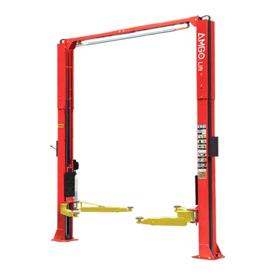
DIRECT-DRIVED TWO POST LIFT
Cargo Claims
If there is any missing or damage of
the cargo during transportation, the
buyer should claim on the carrier,
since the invoices issued by the
carrier is made out to the buyer.
Address:
SC Division: 1931 Joe Rogers Jr Blvd, Manning, SC 2912, USA
TX Division: 4310 Adler Dr., Suite #200, Dallas TX 75211, USA
Model: OH-10
△
DANGER
!
Read the entire contents of this manual before
using this product. Failure to follow instructions
and safety precautions could result in serious
injury or even death. Make sure all other
operators also read this manual. Keep this
manual near the machine so that it can be seen
by all users. By proceeding with installation and
operation, you agree that you are fully
understand the contents of this manual and take
full responsibility for the use of the product.
Original
Advertisement
Table of Contents

Related Manuals for AMGO OH-10


Summary of Contents for AMGO OH-10
- Page 1 Original DIRECT-DRIVED TWO POST LIFT Model: OH-10 △ DANGER Read the entire contents of this manual before using this product. Failure to follow instructions and safety precautions could result in serious injury or even death. Make sure all other Cargo Claims operators also read this manual.
-
Page 2: Table Of Contents
CONTENTS PROFILE ..................1 OWNER/EMPLOYER RESPONSIBILITIES ..........2 IMPORTANT SAFETY INSTRUCTIONS ..........3 SAFETY WARNING LABEL ..............5 I. PRODUCT FEATURES AND SPECIFICATIONS ........6 II. INSTALLATION REQUIREMENT ............. 9 III. INSTALLATION STEPS ..............11 IV. EXPLODED VIEW ..............32 V. TEST RUN ................38 VI. -
Page 3: Profile
PROFILE The two post lift is a commonly used vehicle repair and maintenance tool that uses a pneumatic hydraulic or electric system that can lift the car up to a certain height so that the vehicle can be placed in a suitable position for inspection and repair. Car lifts can be divided into pneumatic and electric, which have the characteristics of safe and reliable, simple structure and quick installation. -
Page 4: Owner/Employer Responsibilities
damage resulting in breach of or delay in the execution of the warranty. The manufacturer reserves the right to design and improve the product and has no obligation to make notice of the changes in advance. The product warranty based on the above clause is based on the model number and serial number of the equipment. -
Page 5: Important Safety Instructions
5.The Owner/Employer shall display the lift manufacturer’s operating instructions; ALI/SM 10-1, ALI Lifting it Right safety manual; ALI/ST-10 ALI Safety Tips card; ANSI/ALI ALOIM-2008 (R2013), American National Standard for Automotive Lifts - Safety Requirements for Operation, Inspection and Maintenance; ALI/WL Series, ALI Uniform Warning Label Decals/Placards;... - Page 6 7. Only trained operators are allowed to handle the lift machine. All untrained persons must stay away from the workplace. Never allow untrained persons to handle or operate the machine. 8. Use the lift properly. Use the lift in the correct way. 9.
-
Page 7: Safety Warning Label
SAFETY WARNING LABEL The above safety WARNING labels used for lifts. ATTENTION Some of the images in this manual are generic, and these images may differ from the lift you purchased. References: Automobile lift Research Institute. Fig.1... -
Page 8: Product Features And Specifications
Fig. 2 I. PRODUCT FEATURES AND SPECIFICATIONS CLEAR-FLOOR DIRECT-DRIVED TWO POST LIFT FEATURES Model OH-10 · Direct-drived minimize the lift wear parts and failure rate. · Self- lubricating UHMW Polyethylene sliders and bronze bush. · Single-point safety release, easy disengage both side simultaneously. - Page 9 Arm Swings View Fig.3 Fig.4 Car in △ CAUTION When driving the vehicle, stay in the middle between the columns. If you hit any part of the lift, you could damage the car or lift.
- Page 10 ATTENTION Please identify the recommended location and shape of vehicle lift points refer “Vehicle lift points for service garage lifting SAE J2184” to determine the center of gravity position of the vehicle. After the car passes, spread the arm to support the support point. Before lifting the vehicle, make sure it is neither front nor rear heavy.
-
Page 11: Installation Requirement
II. INSTALLATION REQUIREMENT A. TOOLS REQUIRED Rotary Hammer Drill (Φ19) Carpenter’s ink marker Hammer Screw Sets Level Bar Tape Measure (7.5m) English Spanner (12") Pliers Ratchet Spanner with Socket (28 Socket Head Wrench (3 ... - Page 12 B. Equipment storage and installation requirements. 1. Store the equipment in a dry, non-moldy, non-flammable environment. 2. The lift is generally approved for indoor installation and use. Outdoor installation is prohibited. 3. When installing the machine, take safety precautions according to the instructions to avoid device damage.
-
Page 13: Installation Steps
4.Power. You need a 220 VAC, 60Hz, current 20A, with a cord larger than 12AWG. 5.Installations: AMGO car lifts are approved for indoor installation and use only. Outdoor installation is prohibited. - Page 14 3/8 of an inch difference over the installation area). Once the floor is not level, consider making the floor flat or change to another location. ATTENTION The AMGO lift installation and concrete construction must meet the latest version of the US national standard "Automotive Hoist-Safety Requirements for Construction, Testing and Verification", ANSI / ALI ALCTV.
- Page 15 B. Use a carpenter’s ink marker line to establish installation layout of base-plate (See Fig.10) Click a line 135” Fig.10 C. Check the parts before assembly. 1. Packaged lift and power unit ( See Fig. 11). Fig. 11 2. Move aside the lift with fork lift or crane, and open the package, take off the lifting arms and parts box to nearby installation site, check the parts according to the shipment parts list and inner package list (See Fig.12).
- Page 16 4. Move aside the parts and check the parts according to the shipment parts list. (See Fig.13 & 14). Parts in the parts box (89) Fig. 14 Parts in the shipment parts list Fig. 13 5. Open the parts bag 1, 2 and 3; check the parts according to the list (See Fig.
- Page 17 D. Install parts of extension columns (See Fig. 16). (Assemble with M6*15 Fig. 16 Hex bolt, lock washer, flat washer, nut) E. Position columns Put down two columns on the installation site paralleled. Position the power-side column according to the actual installation site. Usually, it is suggested to install power-side column on the right-front side of vehicle entry direction which vehicles.
- Page 18 2. Low Setting, connecting the upper holes of outer columns with inner columns (See Fig. 18). Assemble with M10*30 Hex bolt, lock washer, dual flat washers and nut Low setting Fig.18 F. Put up the columns on the installation, install the anchor bolts. Check the Columns plumpness with level bar, and adjusting with the shims if the columns are not vertical.
- Page 19 The AMGO lift installation and concrete construction must meet the latest version of the US national standard "Automotive Hoist-Safety Requirements for Construction, Testing and Verification", ANSI / ALI ALCTV.
- Page 20 2. Hang the hook of top beam B on the other outer column, and then bolted with top beam A. (See Fig. 21) Assemble with Hex bolt(M12*25 ), lock washer, flat washer and nut Tighten the anchor bolts with socket wrench. Re-torque the anchor bolts to 150N.m Fig.
- Page 21 H. Install the limit switch control bar and limit switch (See Fig. 22). 1. Fix the limit switch control bar on to the top beam. Power-side Off-side Fix the control bar support bracket with Hex bolt( M10*20 ),lock washer, flat washer Control bar support bracket...
- Page 22 I. Install safety device (See Fig. 24 & Fig. 25). Power-side safety device Fig.24 39A 39B Offside safety device Fig.25 △ DANGER Make sure the safety device are properly installed before using the lift.
- Page 23 Install cables Lift the carriages up and make them be locked at the same level. 1. Cable connecting of low setting installation. (See Fig. 26). Setting installation hole Cable2 Cable1 Hex nut (M16) Cable2 Fig. 26...
- Page 24 2. Cable connecting of high setting installation. 2.1. Cable across from the bottom of the carriage and pull it out from the hole of carriage, then tighten two cable nuts. (See Fig. 27). High Setting installation holes Screw the two cable nuts Cable Connecting direction Cable connecting direction Fig.
- Page 25 2.2 Connecting cable for high setting (See Fig. 28). Cable 2 Cable 1 Hex nut (M16) Cable 2 Fig. 28...
- Page 26 K. Install power unit (See Fig. 29) Fig.29...
- Page 27 L. Install oil hose. 1. Connect 2 oil hoses as shown. (See Fig.30) Fig.30...
- Page 28 2. Follow these steps to connect the oil hose with power unit. Oil outlet port(Left) Oil outlet port(Right) Socket iron plug Socket iron plug Assemble 90° fitting to connect Remove the socket iron plug from the power unit with oil hose. the right oil outlet port.
- Page 29 M. Install protective cover. (Fig.32) Install with M6*16 socket bolt, spring wahser and washer. Cable limit plate 1. Screw M6*40 round head bolt slightly; 2. Install protective cover, tighten the round head bolts. Only for high setting Install protective cover to secure oi hose.
- Page 30 N. Install safety cable (See Fig. 33) (Install safety cable start from off-side safety device, then pass it through the top beam, finally connect to power-side safety device.) Safety cable across pulley bracket Wire of limit switch Oil hose Install safety cable from off-side safety device.
- Page 31 O. Install lifting arms, then install spring on the arm pin. Last install guard bar. The process of engaging arm lock and moon gear: Lowing the carriages down to the lowest position, then use the 8 socket head wrench to loose the socket bolt (See Fig.
- Page 32 P. Tighten all the hydraulic fittings, fill the reservoir with hydraulic oil. Note: In consideration of Hydraulic Power Unit’s durability and keep the equipment running in the perfect condition, please use Hydraulic Oil 46#. Q. Install electrical system Connect the power source according to the nameplate of the motor. Note:1.
- Page 33 2. Connecting the limit switch wire: Remove the short wire that connects # 4 and # A2 as shown in Fig.40. Then according to the wire number of the limit switch, connect them respectively to terminal 4# of control button and A2# of AC contactor. Power source wires Remove this short wire...
-
Page 34: Exploded View
IV. EXPLODED VIEW Fig. 42... - Page 35 PARTS LIST Item Part No. Description QTY. 10206009 Small pulley(White) 11217379 Safety Cable Bracket 1002735010 Hex bolt(M10*35), Lock washer, nu 1061K074 Protective ring 11217024 Oil hose retainer 1002215011 Hex bolt(M6*15), lock washer, flat washer, nut 11279024 Off-side inner column 11279023 Power-side inner column 1002215006 Hex bolt(M10*30),lock washer,dual flat washers,nut...
- Page 36 Item Part No. Description QTY. 10217032 Cable connecting pin 11217033 Nylok Nut 11217406 Off-side safety cover 1002735011 Hex bolt(M6*15), flat washe 11217029 Safety Pulley Bracket 10209015 Slider 11217046 Arm lock bar(Right) Cylinder φ50*1727(L=68”) 1002216000 10209111 Cylinder protective ring 11279004 Carriage 10209016 Plastic cover Protective rubber block...
- Page 37 Item Part No. Description QTY. 10209066 Hex nut M16 Cable assy. φ9.52*10048mm(L=395-19/32") 10206064A 10211016 T fitting Oil hose assy. 1/4”*5350mm(L=210-5/8") 10206130-01 10209064 Straight fitting 11233009 Straight fitting 10206062 Straight fitting Oil hose assy. 1/4”*4470mm(L=175-31/32") 10206132-01 10209060 Power unit 90° fitting 1102075001 Cable limit plate 1002735009...
- Page 38 4.2 Front left arm assy. (1102214005C) explosive view Fig.44 Item Part No. Description QTY. 10206048 Socket bolts M10*30 10209039 Lock Washer φ10 10209022 Flat Washer φ10 11206049 Moon gear 1102214005A Outer arm-Front left 1102214009A Middle arm - Front 10201149 Round head bolt M8*12 1102214010A Inner arm - Front 4.3 Front right arm assy.
- Page 39 4.4 Cylinder (1002216000) explosive view Fig. 46 Item Part No. Description QTY. 30-1 10209069 O-ring 30-2 10209070 Bleeding Plug 30-3 1002576003 Support Ring 30-4 11720114 Pressure Compensated Flow Restrictor (0.7 Spring) 30-5 10209071 Wear ring 30-6 10209072 Y-ring OSI 30-7 10209073 O-Ring 30-8...
-
Page 40: Test Run
4.5 Illustration of hydraulic valve for hydraulic power unit Release Oil inlet port Relief valve valve Oil outlet port Throttle Release valve handle Check valve Fig.47 V. TEST RUN 1. Adjustment of synchronous cable (See Fig. 48) Use an open spanner to clamp the cable joint, and use a ratchet wrench to tighten the cable nut until the two synchronous cables are adjusted to a certain tension force and Adjust... - Page 41 4. Adjust the lower speed If necessary, you can adjust the lower speed of the lift by turning the throttle valve clockwise to decrease it, or counterclockwise to increase the lower speed. Throttle Valve Throttle Valve Clockwise to decrease the down speed Counterclockwise to increase the down speed Fig.
-
Page 42: Operation Instructions
6. Move the lifting arms to the vehicle’s lifting point; ATTENION: Use the carrier adapter provided by the AMGO manufacturer. Swing the lifting arms under the vehicle, lift the vehicle lifting points as recommend by the vehicle manufacturer. - Page 43 Safety lock working status Safety lock being open Fig.53 Fig.54 To lower vehicle 1. Clear obstructions around and under the lift and no people around the lift; 2. Push UP button to raise the vehicle slightly, and then unlock the safety device, lower vehicle by pushing release handle on the power unit.
-
Page 44: Maintenance Schedule
Lift Lift Points Points Pickup Truck/Van Stub Frame Lift Lift Points Points Perimeter Frame Unitized body Fig.55 △ WARNING Any special or modified vehicles or vehicles with abnormally short or long wheelbases cannot be lifted in a two post lift. Please contact the vehicle manufacturer for details on lifting or jacking. - Page 45 DO NOT use the lift until the bolt has been replaced. △ WARNING Always use parts provided by the AMGO lift manufacturer or authorized by the manufacturer, if you use non-standard parts obtained from other sources resulting in damage to the lift is not covered by the warranty, and the use of non-standard parts may endanger the safety of the installer/operator.
- Page 46 Every six months: 1. Make a visual inspection of all moving parts for possible wear, interference or damage. 2. Check and adjust as necessary, equalizer tension of the cables to insure level lifting. 3. Check columns for plumpness. 4. Check Rubber Pads and replace as necessary. 5.
-
Page 47: Trouble Shooting
VIII.TROUBLE SHOOTING TROUBLE CAUSE REMEDY 1. Start Button does not work 1. Replace start button 2. Wiring connections are not in good 2.Repair all wiring connections condition Motor does not 3. Motor burned out 3. Repair or replace motor 4. AC contactor burned out 4. -
Page 48: Car Lift Safety Tips
IX. CAR LIFT SAFETY TIPS Put this safety tips in a place where you can always alert the operator. Please reference to the lift manufacturer’s manual for specific information about the lift. 1. Check the lift daily. If the machine breaks down or has damaged parts, do not operate, and use the parts of original equipment to repair. - Page 49 AMGO HYDRAULIC CORPORATION 1931 Joe Rogers Blvd, Manning, South Carolina, Zip: 29102 Manual No.:722287021 Tel: (803) 505-6410 Revised date:2023/10 Fax: (803) 505-6410...
Need help?
Do you have a question about the OH-10 and is the answer not in the manual?
Questions and answers