Table of Contents
Advertisement
Advertisement
Table of Contents

Related Manuals for AMGO BP-9


Summary of Contents for AMGO BP-9
- Page 1 TWO POST LIFT Model:BP-9...
-
Page 2: Table Of Contents
CONTENTS Product Features and Specifications..........1 Installation Requirement ……………………………………………………………………..3 Step of Installation……………………………………………………………………………...5 Exploded View ................17 Test Run ..................24 Operation Instruction ..............26 Maintenance ................27 Trouble Shooting ..............28 Lift Disposal ..................28... -
Page 3: Product Features And Specifications
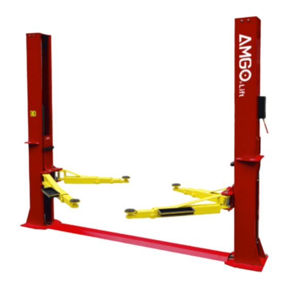
I. PRODUCT FEATURES AND SPECIFICATIONS FLOORPLATE CHAIN-DRIVE MODEL FEATURES Model BP-9 (See Fig. 1) . Compact Floor-plate design, provide unobstructed floor space · Dual hydraulic cylinders is designed and manufactured according to standard, utilizing imported seals · Self- lubricating UHMW Polyethylene sliders and bronze bush ·... - Page 4 Arm Swings View 45-5/8” 26-7/8” 99" 45-5/8” 26-7/8” Fig.2...
-
Page 5: Installation Requirement
II. INSTALLATION REQUIREMENT A. TOOLS REQUIRED Rotary Hammer Drill (Φ19) Carpenter’s Chalk Hammer Screw Sets Level Bar Tape Measure (7.5m) English Spanner (12") Pliers Ratchet Spanner With Socket (28 Socket Head Wrench (6 ... - Page 6 B. Equipment storage and installation requirements. The equipment should be stored or installed in a shady, normal temperature, ventilated and dry place. C. The equipment should be unload and transfer by forklift. Fig.4 SPECIFICATIONS OF CONCRETE (See Fig. 5). Specifications of concrete must be adhered to the specification as following. Failure to do so may result in lift and/or vehicle falling.
-
Page 7: Step Of Installation
III. STEPS OF INSTALLATION A. Location of Installation Check and insure the installation location (concrete, layout, space size etc.) is suitable for lift installation. Use a carpenter’s chalk line to establish installation layout of base-plate (See Fig. 6). 10-1/8” 6-Φ7/8” Chalk line 图六... - Page 8 3. Loosen the screws of the upper package stand, take off the upper column and remove the package stand. 4. Move aside the parts and check the parts according to the shipment parts list. (See Fig. 9, Fig. 10). Fig.9 Fig.
- Page 9 D. Position power-side columns Lay down two columns on the installation site parallelly, position the power-side column according to the actual installation site. Usually, it is suggested to install power-side column on the front-right side from which vehicles are driven to the lift (See Fig.
- Page 10 F. Fix anchor bolts 1. Prepare anchor bolts (See Fig. 14) Washer Lock washer Fig.14 2. Using the prescribed rotary hammer drill, and drill all the anchor holes and install the anchor bolts. Then tighten the anchor bolts (See Fig. 15). Note: Torque of Anchors is 150N.m .Minimum embedment of Anchors is 3-1/2’’.
- Page 11 H.Connecting the cables 1. Connect the cables follow step a to f. (See Fig. 17). e. Pull out the cable from bottom to top b. Push the carriages higher and hang the than chain pulley, cable pass cable on big through the top end of the pulley carriages and pass through...
- Page 12 I. Install cable (See Fig. 18) The fitting of cable pass through the hole of the carriages and be screwed with two cable nuts. Fig.18...
- Page 13 J. Assembly oil hose assy. (See Fig. 19) Fig. 19...
- Page 14 K. Install hydraulic power unit and oil hose assy. (See Fig. 20). Note: Tighten oil hose and power unit fittings, avoid oil leakage. The oil hose of power unit should be fixed with retainer. After installing the fitting of power unit , Locking the nut using 19# ratchet spanner Fix the oil hose by retainer.
- Page 15 L. Install safety cable (See Fig. 21). 1. Assemble safety cable from off-side safety assy. NOTE: 2. Pay attention to the connecting direction of safety cable. Safety cable connecting View A direction View B Fig. 21...
- Page 16 M. Assemble floor cover and protective rubber sets (See Fig. 22). Protective Floor Cover rubber sets Fig.22...
- Page 17 N. Install lifting arms and adjust the arm locks 1. After installing the lifting arms (See Fig.23). 2. Lowing down the carriage to the lowest position, use 17# spanner to loose fixed nut(see Fig.24), 3. Adjust the arm lock follow the arrow direction(see Fig.25), 4.
- Page 18 P. Install Electrical System Connect the power source on the data plate of Power Unit. Note: For the safety of operators, the power wiring must contact the floor well. Single phase motor 1. Circuit diagram (See Fig. 27) Fig. 2. Connection step (See Fig.
-
Page 19: Exploded View
IV. EXPLODED VIEW Model BP-9 Fig.29... - Page 20 PARTS LIST Item Part# Description Qty. Note 11205039 Power-side column 10209011 Plastic pulley for safety device(white) 10209010 Snap ring φ10 10209008 Safety device protect cover 10209009 Cap head bolt M6*8 10206006 Washer φ12 10206023A Hex nut M12 071101 Manual power unit 11206002 Safety pin 10209007...
- Page 21 Item Part# Description Qty. Note 10206190 Tool tray (Short) 11206191 Short guardrail 11205005 Connecting plate 10209043 Hex Bolt M8*20 10209046 Hex Bolt M10*35 11205006 Top plate 11209045 Pulley 10209057A Bronze Bush φ25.4*φ19.1*14.5 11205040 Off-side column 10209049 Plastic pulley (black) 11203264 Offside safety device 11203784 Coupling...
- Page 22 4.1 Chain pulley seat assy. exploded view (11203176) Description QTY. Item Part# 11203040 Pin for chain pulley 10203004A Bronze bush φ31*φ25.1*21 10640109 Washer φ44*φ25.2*2 1102023002 Chain Pulley φ105*41 81400335 Socket bolt M5*10 10209143 Spring Washer Φ5 10420152 Washer Φ5 11201152 Chain stop plate 10217020 Bronze bush φ31*φ25.1*16...
- Page 23 4.3.Cylinders(10201008A) exploded view: Fig. Part list for Cylinder Description QTY. Description QTY. Item Part# Item Part# Piston rod 24-1 11201027A Piston rod 24-8 11201037 adjusting sleeve 24-2 11201028 Piston 24-9 10209078 Dusty ring 24-3 10206069 O ring 24-10 10201032 O ring 24-4 10201029 Support ring...
- Page 24 4.4 MANUAL POWER UNIT(071101) Manual Power unit 220V/60Hz Fig.33...
- Page 25 Filter 81400290 81400413 Steel Motor Push button 10420070 AC connector 41030055 Motor terminal box cover 81400287 71111216 AMGO power unit label 81400560 Throttle valve 81400266 Relief valve 81400284 Inner hex iron plug 10720118 Hair pin 81400451 Release valve handle 10209020...
-
Page 26: Test Run
Illustration of hydraulic valve for hydraulic power unit Protective ring Relief Oil return valve port Release Throttle valve valve Check valve Oil outlet port Handle for release valve Fig.34 V. TEST RUN 1. Adjustment of synchronous cable (See Fig.35) Push button “UP” to lift the carriages up to the position that the cable nut is over chain pulley and lock the two vehicle carriages on the same grating of safety lock. - Page 27 3. Adjust the lowering speed You can adjust the lowering speed of the lift if needing: screw the throttle valve clockwise to decrease the lowering speed, or counterclockwise to increase the lowering speed. Throttle valve Throttle valve Counterclockwise, increase lowering speed Adjust clockwise, decrease lowering speed Fig.
-
Page 28: Operation Instruction
VI. OPERATION INSTRUCTIONS Please read the safety tips carefully before operating the lift To lift vehicle 1. Keep clean of site near the lift; 2. Position lift arms to the lowest position; 3. To shortest lift arms; 4. Open lift arms; 5. -
Page 29: Maintenance
VII. MAINTENANCE SCHEDULE Monthly: 1. Re-torque the anchor bolts to 150 Nm; 2. Check all connectors, bolts and pins to insure proper mounting; 3. Lubricate cable with lubricant; 4. Make a visual inspection of all hydraulic hoses/lines for possible wear or leakage; 5. -
Page 30: Trouble Shooting
VIII.TROUBLE SHOOTING TROUBLE CAUSE REMEDY 1. Button does not work 1. Replace button 2. Wiring connections are not in good 2.Repair all wiring connections Motor does not condition 3. Motor burned out 3. Repair or replace motor 4. AC contactor in damage 4. - Page 31 AMGO HYDRAULIC CORPORATION 1931 Joe Rogers Blvd, Manning, South Carolina, USA Zip: 29102 Tel: (803) 505-6410 Fax: (803) 505-6410 Manual Part No. : 72229304 Revision Date: : 2022/02...
Need help?
Do you have a question about the BP-9 and is the answer not in the manual?
Questions and answers