Table of Contents
Advertisement
Quick Links
Advertisement
Table of Contents

Related Manuals for AMGO OHX-10


Summary of Contents for AMGO OHX-10
- Page 1 Original TWO POST LIFT Model: OHX-10 / OHX-10H...
-
Page 2: Table Of Contents
CONTENTS Product Features and Specifications ..........1 Installation Requirement .............5 Steps of Installation ..............6 Exploded View ................32 Test Run ...................41 Operation Instruction ..............43 Maintenance ................44 Trouble Shooting ...............45 Lift disposal ................45... -
Page 3: Product Features And Specifications
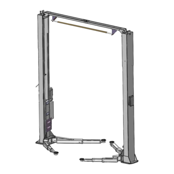
I. PRODUCT FEATURES AND SPECIFICATIONS CLEAR-FLOOR DIRECT-DRIVED MODEL FEATURES Model OHX-10 (See Fig. 1) · Direct-drived design, minimize the lift wear parts and breakdown ratio · Dual hydraulic cylinders, designed and made as USA standards, utilizing oil seal in cylinder ·... - Page 4 Model OHX-10H (See Fig. 2) · Direct-drived design, minimize the lift wear parts and breakdown ratio · Dual hydraulic cylinders, designed and made as USA standards, utilizing oil seal in cylinder · Self- lubricating UHMW Polyethylene sliders and bronze bush ·...
- Page 5 Arm Swings View Car in Fig. 3...
- Page 6 Swing and extending the arms to the lifting point of vehicle Fig. 4...
-
Page 7: Installation Requirement
II. INSTALLATION REQUIREMENT A. TOOLS REQUIRED Rotary Hammer Drill (Φ3/4) Carpenter’s Chalk Screw Sets Hammer Tape Measure (7.5m) Level Bar Pliers English Spanner (12") Socket Head Wrench (6 Ratchet Spanner with Socket (28 ... -
Page 8: Steps Of Installation
B. SPECIFICATIONS OF CONCRETE (See Fig. 6) Specifications of concrete must be adhered to the specification as following. Failure to do so may result in lift and/or vehicle falling. 1. Concrete must be thickness 4” minimum and without reinforcing steel bars, and must be dried completely before the installation. - Page 9 C. Check the parts before assembly. 1. Packaged lift and hydraulic power unit ( See Fig. 8). Fig. 8 2. Move aside the lift with fork lift or hoist, and open the extension packing carefully, take off the lifting arms and parts box from upper and inside the column, then move them to location nearby installation site, check the parts according to the shipment parts list (See Fig.9).
- Page 10 Parts Bag 1 Fig. 12 6. Open the Parts Bag 3 of parts and check the parts according to parts bag list (See Fig. & 14). Fig. 13 Parts Bag 3 OHX-10 Accessories Parts Bag 3 Fig. 14 OHX-10H Accessories...
- Page 11 D. Place the two columns in parallel on the ground of installation position, and determine the installation position of the power side column according to the condition of the installation site. Under normal circumstances, the power side column is installed on the right side of the entering direction; then install the oil hose.
- Page 12 F. Mounting column assemble. 1. OHX-10 mounting column assemble. Fig.17 & 18. A View B View Off-side column Power-side column Fig. 17 Fig. 18 C Magnified view...
- Page 13 2. OHX-10H Mounting column assemble. Fig. 19 A Magnified view Off-side column Power-side column Fig.19...
- Page 14 2.1 Place the two columns in parallel on the ground of the installation position, and determine the installation position of the power-side column according to the condition of the installation site. Under normal circumstances, the power-side column is installed on the right side of the entering direction;...
- Page 15 G. Vertical leveling of columns (See Fig. 21) 1. OHX-10 Put the columns on the installation layout of base-plate, install the anchor bolts. Check the Columns plumpness with level bar, and adjusting with the shims if the columns are not vertical. Do not tighten the Anchor Bolts.
- Page 16 2. OHX-10H Put the columns on the installation layout of base-plate, install the anchor bolts. Check the Columns plumpness with level bar, and adjusting with the shims if the columns are not vertical. Do not tighten the Anchor Bolts. (See Fig. 22) Width: 112-1/4”...
- Page 17 H. Install overhead top beam (See Fig. 23) Only OHX-10H Install the top beam with equipment Top beam connecting groove assemble holes Fig.23...
- Page 18 I. Install the limit switch control bar and limit switch (See Fig. 24). Fix the control bar support → Power-side bracket with Hex bolt M10*20,nuts, lock washer nut and washer → Off-side Control bar support bracket Hex bolt Limit switch (M8*35mm) Hex bolt control bar...
- Page 19 Fig.26 J. Install cables. Lift up the carriage to the same level of safety lock. 1. OHX-10 cable connection. Cables cross over from bottom of the carriages and be pulled out from the square hole of carriages, then screw the two cable nuts (See Fig.
- Page 20 2. OHX-10H Low setting cable connection (See Fig. 28) Note: the cable should go inside the carriage. (Low setting installation holes) Fig.28...
- Page 21 3.OHX-10H High setting cable connection Cables cross over from bottom of the carriages and be pulled out from the square hole of carriages, then screw the two cable nuts (See Fig. 29). (High setting installation holes) Nuts lock each other Fig.29...
- Page 22 K. Install oil hose and fitting 1. OHX-10 (See Fig.30). A Magnified view Fig.30...
- Page 23 2. OHX-10H Oil hose Installation (See Fig. 31). 84、85 Install only when installing in high setting. Not required for low setting. A Magnified view Fig.31...
- Page 24 Follow these step to connect the oil hose of power unit. (See Fig. 32) Left outlet port Right outlet port Iron Plug A. Remove Iron Plug in the right side. B. Install power unit 90° fitting. Red Plug D. Install the iron plug from step A to C.
- Page 25 L. Install safety cable (See Fig. 33) Wearing wire cable A side B side Fig.33...
- Page 26 Note: Don’t cross the oil hose and safety cable (See Fig. 34, 35 & 36). Safety Cable Oil hose Power-side Safety Device Off-side Safety Device Fig. Fig. The safety cable no Oil hose need to cross inside the wire clamp on the top beam.
- Page 27 3. Adjust the arm lock as direction of arrow (See Fig. 39) Locking the bolts Adjust the arm lock Fig. 39 Fig. 40 Adjusting moon gear and Locking the bolts after the moon arm lock to mesh. gear and arm lock engaged well. 4.
- Page 28 Motor wiring diagram of single phase power unit Circuit diagram Limit switch control button Fig. Power supply wires Power supply wires Wire NC# Remove this wire Wire C# Fig. 42 Fig.43 Limit switch wire...
- Page 29 *Optional width extension kits 1. Install the limit switch control bar and top beam (See Fig. 44). Connect the width extension kits by these holes Fig. 44 2. OHX-10 Install the width extension kits 2.1 Oil hose install 118-1/8” Fig.45...
- Page 30 2.2 OHX-10: cable connection Cables cross over from bottom of the carriages and be pulled out from the square hole of carriages, then screw the two cable nuts (See Fig. 46). Nuts lock each other Fig.46 Optional parts list OHX-10...
- Page 31 3. OHX-10H: width extension kits installation. (Fig.47) 3.1 Oil hose install 118-1/8” Fig.47...
- Page 32 3.2 OHX-10H: Cable connection for low setting. (Fig. 48) Note: The cables install inside the carriage. Low setting installation holes Fig.48...
- Page 33 3.3 OHX-10H: Cable connection for high setting (Fig. 49). Cables cross over from bottom of the carriages and be pulled out from the square hole of carriages, then screw the two cable nuts. Nuts lock each other Fig.49 Optional parts list OHX-10H Item Part#...
-
Page 34: Exploded View
IV. EXPLODED VIEW OHX-10 Fig. 50... - Page 35 OHX-10H Fig. 51...
- Page 36 PARTS LIST FOR OHX-10 and OHX-10H QTY. Item Part# Description OHX-10 OHX-10H 10206017 Hex Bolt M10*20 10209039 Lock Washer φ10 10209022 Washer φ10 10209021 Hex Nut M10 10209009 Cap Head Bolt M6*8 10209008 Safety device protective cover 10209010 Snap ring (φ10)
- Page 37 QTY. Item Part# Description OHX-10 OHX-10H 10209015 Slider block 10209016 Carriage plastic cover 1102563000A Carriage 10209018 Protection rubber 10209019 Screw M6*16 10520023 Snap ring φ38 11217168 Arm pin 11217046A Arm lock handle (Left) 10206050A Spring 11217046 Arm lock handle (Right)
- Page 38 QTY. Item Part# Description OHX-10 OHX-10H 11209053B Stackable adaptor (5”) 11209054A Stackable adaptor bracket 10680003 Hex bolt M8*12 10209059 Anchor bolt 3/4*5-1/2 10201090 Shim(1mm) 10620065 Shim(2mm) 10209066 Hex Nut M16 1002561004 Cable assy. φ9.52*9640mm 1002571005 Cable assy. φ9.52*10860mm 1002561005-01 Oil hose assy. 1/4*5115mm 1002571002-01 Oil hose assy.
- Page 39 1. Rear arm (10279011) explosive view Fig.52 Item Part# Description QTY. 10206048 Socket bolt M10*30 10209039 Lock washer φ10 10209022 Washer φ10 11206049 Moon gear 11206192 Outer arm - rear 10201149 Cup head bolt M8*12 11206193 Inner arm - rear 2.
- Page 40 3. Right front arm (10279010) explosive view Fig.54 Item Part# Description QTY. 10206048 Socket bolt M10*30 10209039 Lock Washer φ10 10209022 Washer φ10 11206049 Moon gear 11279006 Outer arm - front right 11206189 Middle arm - front 10201149 Cap head bolt M8*12 11201049A Inner arm - front 4.
- Page 41 10209071 Support Ring 30-4 10209072 Y-ring OSI 30-5 10209073 O-ring 30-6 11209074 Piston 30-7 10209075 O-Ring 11209076 Piston rod OHX-10 30-8 1102576002 Piston rod OHX-10H 30-9 11209077 Piston Rod Fitting 30-10 10209078 Dust wing 30-11 11209079 End cap 30-12 10209080...
- Page 42 Magnet 81400290 Filter net 81400413 Steel plate motor 10420070 Button switch 41030055 AC contractor 81400528 Motor wiring cover 71111216 AMGO plate 81400560 Throttle valve 81400266 Relief valve 81400284 Socket iron plug 10720118 Elastic pin 81400451 Release handle 10209020 Plastic ball for Release Handle...
-
Page 43: Test Run
6. Illustration of hydraulic valve for hydraulic power unit Relief valve Oil return port Release valve Throttle valve Left Oil Outlet port Handle of Release Right Oil Outlet valve Port Check valve Fig. 57 V. TEST RUN 1. Adjustment of synchronous cable (See Fig. - Page 44 4. Adjust the lowering speed You can adjust the lowering speed of the lift if needing: screw the throttle valve clockwise to decrease the lowering speed, or counterclockwise to increase the lowering speed. Throttle valve Throttle valve Adjust clockwise, decrease lowering speed Counterclockwise, increase lowering speed Fig.
-
Page 45: Operation Instruction
VI. OPERATION INSTRUCTIONS Please read the safety tips carefully before operating the lift To lift vehicle 1. Keep clean of site near the lift; 2. Position lift arms to the lowest position; 3. To shortest lift arms; 4. Open lift arms; 5. -
Page 46: Maintenance
VII.MAINTENANCE SCHEDULE Monthly: 1. Re-torque the anchor bolts to 150 N.M; 2. Check all connectors, bolts and pins to insure proper mounting; 3. Lubricate cable with lubricant; 4. Make a visual inspection of all hydraulic hoses/lines for possible wear or leakage; 5. -
Page 47: Trouble Shooting
VIII.TROUBLE SHOOTING TROUBLE CAUSE REMEDY 1. Button does not work 1. Replace button 2. Wiring connections are not in good 2. Repair all wiring connections Motor does not condition 3. Motor burned out 3. Repair or replace motor 4. AC contactor burned out 4. - Page 48 AMGO HYDRAULIC CORPORATION 1931 Joe Rogers Blvd, Manning, South Carolina, USA Zip: 29102 Tel: (803) 505-6410 Fax: (803) 505-6410 图 Manual No.:72228107 修 Revised date:2022/10...
Need help?
Do you have a question about the OHX-10 and is the answer not in the manual?
Questions and answers