Table of Contents
Advertisement
Quick Links
Advertisement
Table of Contents

Related Manuals for Advantech ECU-150 Series


Summary of Contents for Advantech ECU-150 Series
- Page 1 User Manual ECU-150 Series...
- Page 2 No part of this manual may be reproduced, copied, translated, or transmitted in any form or by any means without the prior written permission of Advantech Co., Ltd. The information provided in this manual is intended to be accurate and reliable.
- Page 3 This product has passed the CE test for environmental specifications when shielded cables are used for external wiring. We recommend the use of shielded cables. This type of cable is available from Advantech. Please contact your local supplier for ordering information.
- Page 4 SELV output, rated 10 to 30Vdc, 1.5 to 0.5A minimum and maxi- mum ambient temperature (Tma) 70 degree C minimum without power source or adapter. If you need further assistance, please contact Advantech for further information. Ensure that the voltage of the power source is correct before connecting the equipment to a power outlet.
- Page 5 If the equipment is used in a manner not specified by the Advantech, the protec- tion provided by the equipment may be impaired. The equipment contains no user-serviceable parts. Do not open, Return to man- ufacturer for servicing. Do not block air ventilation holes.
- Page 6 Les matériels sont destinés à être installés dans des EMPLACEMENTS À ACCÈS RESTREINT ATTENTION! Danger d'explosion si la batterie est mal remplace. Remplacer unique- ment par le meme type ou equivalent recommandé par le fabricant. Jeter les piles usagées selon les instructions du fabricant. ECU-150 Series User Manual...
-
Page 7: Table Of Contents
Jumper Setting................15 Figure 3.8 Jumper Setting ............15 Table 3.6: Jumper Setting of Terminal Resistor For COM(1~4) 16 Extension and Installation ............... 16 3.3.1 Extension Socket and Expansion Module List ......16 Figure 3.9 Extension Socket............16 ECU-150 Series User Manual... - Page 8 Figure 3.11Assembly of Expansion Module ....... 17 3.3.3 Wall-mounted and DIN-Rail Installation........18 Figure 3.12Wall-mount and DIN-Rail Installation ....... 18 3.3.4 Installing a Wireless module Card and Antenna (Optional) ..19 Figure 3.13Installing a Wireless module Card and Antenna ..19 ECU-150 Series User Manual viii...
-
Page 9: Chapter 1 Overview
Chapter Overview... -
Page 10: Introduction
Power Requirements: 10 ~ 30 V Dimensions (W x D x H): Basic Unit: 30 x 100 x 93mm Double Stack: 55.1 x 100 x 93mm Enclosure: Aluminum Housing Operating System: Yocto 4.14/Ubuntu 22.04 ECU-150 Series User Manual... -
Page 11: System
Operating Temperature: -40 ~ 70°C Storage Temperature: -40~85°C Humidity: 5~95% (non-condensing) 1.2.5 SSH Login User Name & Password User Name: root Password: no password (press "Enter") 1.2.6 Default IP LAN1: 10.0.0.1 LAN2: 11.0.0.1 ECU-150 Series User Manual... -
Page 12: Software
Caution! Always ground yourself to remove any static electric charge before touching ECU-150 Series. Modern electronic devices are very sensitive to static electric charges. Use a grounding wrist strap at all times. Place all electronic components on a static-dissipative surface or in a static- shielded bag. -
Page 13: Chassis Dimensions
Chassis Dimensions Figure 1.1 ECU-150 Chassis Dimensions Packing List The accessory package of ECU-150 contains the following items: (A) ECU-150 (B) Warranty card (C) RoHS (D) Connector (E) Din-rail ECU-150 Series User Manual... - Page 14 ECU-150 Series User Manual...
-
Page 15: Chapter 2 Hardware Functionality
Chapter Hardware Functionality... -
Page 16: Overview
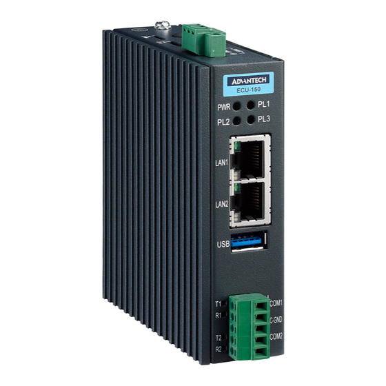
Overview The following figures show the panel configuration on ECU-150. More information of each peripheral is included in the following sections. Figure 2.1 ECU-150 Overview ECU-150 Series User Manual... -
Page 17: Led Status Indicators
The LEDs in the front panel can be divided into 3 groups: Figure 2.2 ECU-150 LED Status Indicator 2.2.1 System Status Indicators: Status Description Green Power is on Power is off Green Customers can define the Programmable LED state accord- ing to the actual need. ECU-150 Series User Manual... -
Page 18: Serial Communication Status Indicator
Blinking, Serial port 2 data being received 2.2.3 Ethernet Status Indicator Color Description Link1 Yellow Lighting, Ethernet not connected Act1 Green Blinking, Ethernet data being transmitted Link2 Yellow Lighting, Ethernet not connected Act2 Green Blinking, Ethernet data being transmitted ECU-150 Series User Manual... -
Page 19: Chapter 3 Wiring And Installation
Chapter Wiring and Installation... -
Page 20: Wiring
PWR V+ DC power input PIN Power Input PWR V- DC power input PIN 3.1.2 Communication Ports Figure 3.2 RS-232/485 Serial Ports (COM1~ COM2) Table 3.2: RS-232/485 Serial Ports (Pin Assignments) Pins RS-232 RS-485 Data- Data+ ECU-150 Series User Manual... -
Page 21: Usb Port
ECU-150 is equipped with one USB 3.0 Type A port for optional extension choice. Figure 3.3 USB Connector Table 3.3: USB Connector Pin Assignment Signal DATA- DATA+ 3.1.4 LAN Port Figure 3.4 LAN Connectors (LAN1~LAN2) Table 3.4: LAN Connector Pin Assignments Assignment Description Transmit+ Transmit- Receive+ Not used Receive- ECU-150 Series User Manual... -
Page 22: Console Port
ECU-150 is equipped with a 3-Pin COM or Micro-USB port as console port for debug- ging. Figure 3.5 Console Port of ECU-150-12A Table 3.5: 3-Pin COM Assignments Assignment COM_Debug_TX COM_Debug_RX COM_ISO_GND Figure 3.6 Console Port of ECU-150-12A1 ECU-150 Series User Manual... -
Page 23: Sd&Sim Card Installation
The installation is shown below. Figure 3.7 SIM & SD Card Slot Jumper Setting 3.2.1 Jumper Setting The motherboard of ECU-150 has two types of jumper for user operation, as shown below. Figure 3.8 Jumper Setting ECU-150 Series User Manual... -
Page 24: Extension And Installation
Extension and Installation 3.3.1 Extension Socket and Expansion Module List ECU-150 could be extended to a 2nd stack for extra communication by adding three types of expansion module through CN12 & CN19 sockets. Figure 3.9 Extension Socket ECU-150 Series User Manual... - Page 25 ECU-150P-P2A Figure 3.10 Expansion Modules 3.3.2 Assembly of Expansion Module Remove the top cover, assemble the expansion module onto ECU-150 aligning to the extension sockets, then fasten the four screws. Figure 3.11 Assembly of Expansion Module ECU-150 Series User Manual...
- Page 26 3.3.3 Wall-mounted and DIN-Rail Installation ECU-150 supports two-in-one type of installation: Wall-mount and DIN-Rail Installa- tion. Figure 3.12 Wall-mount and DIN-Rail Installation ECU-150 Series User Manual...
- Page 27 3.3.4 Installing a Wireless module Card and Antenna (Optional) For optional wireless module card and antenna, please contact Advantech for the fol- lowing wireless solution kit. Figure 3.13 Installing a Wireless module Card and Antenna ECU-150 Series User Manual...
- Page 28 No part of this publication may be reproduced in any form or by any means, electronic, photocopying, recording or otherwise, without prior written permis- sion of the publisher. All brand and product names are trademarks or registered trademarks of their respective companies. © Advantech Co., Ltd. 2024...
Need help?
Do you have a question about the ECU-150 Series and is the answer not in the manual?
Questions and answers