Table of Contents
Advertisement
Quick Links
WL2000IT
MANUAL
Waterlogic Trading LTD,
WLI Trading Limited, Second Floor, Suite 4, Beacon Court, Sandyford, Co. Dublin, Ireland
Tel: + 353 (0) 1293 1960
Fax: + 353 (0) 1293 1052
For Technical Support Email: support@waterlogicsupport.zendesk.com
WLI (UK) LTD – Global Headquarters Grenfell Road, Maidenhead, Berkshire, SL6 1HN, United Kingdom
Advertisement
Table of Contents
Troubleshooting

Related Manuals for WaterLogic WL2000IT


Summary of Contents for WaterLogic WL2000IT
- Page 1 WL2000IT MANUAL Waterlogic Trading LTD, WLI Trading Limited, Second Floor, Suite 4, Beacon Court, Sandyford, Co. Dublin, Ireland Tel: + 353 (0) 1293 1960 Fax: + 353 (0) 1293 1052 For Technical Support Email: support@waterlogicsupport.zendesk.com WLI (UK) LTD – Global Headquarters Grenfell Road, Maidenhead, Berkshire, SL6 1HN, United Kingdom...
- Page 2 The Waterlogic WL2000IT Water Treatment System provides exceptional quality and great tasting water with every use. INTRODUCTION Carefully read and follow all instructions to ensure proper and efficient operation of your WL2000IT Water Treatment System. Contact Waterlogic or an Authorized Waterlogic Dealer if you have any questions.
-
Page 3: Table Of Contents
• Free Standing Draining Procedure ......... 40 • Installation Instructions ............41 TROUBLESHOOTING GUIDE • Power Troubleshooting ............43 • Dispense Troubleshooting ............. 46 • Cold Water Troubleshooting ..........55 • Hot Water Troubleshooting ........... 56 WL2000IT Manual Page 3 - Revision:EU-2020-10-13... -
Page 4: Safety Alert Symbols
(RCD) having a rated residual operating current not exceeding 30mA. Use only Waterlogic supplied power cord. Never use extension cords or power strips to connect unit. Do not use if the power supply cord is damaged. Always unplug from power supply prior to servicing. - Page 5 TIP HAZARD. Dispenser could tip or fall causing serious injury. Always install unit on a firm, flat, and level surface and secure the WL2000IT Water Treatment System to the base cabinet with the screw provided to lock the components together. Secure unit to cabinet, wall, or floor if needed.
-
Page 6: Features And Benefits
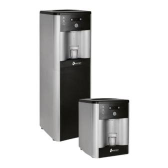
The Tower Model is also available in Cold Only Water Version. High Volume Storage and Water Capacity The WL2000IT has a 4 Litre cold tank capacity in the free standing model, 2 Litre cold tank capacity in the mini model and 1.5 Litre hot water tank capacity in both models. -
Page 7: Certifications
Intertek Labs (ETL) Certified the WL2000IT Water Treatment System to ANSI/UL 399 Standard for Drinking Water Coolers. BPA Free - Waterlogic tests for BPA and declares that all of its products are Bisphenol-A FREE and contain no harmful BPA plastics. - Page 8 WL2000IT-M F-2002-M-CA-UT6-CS-WLT Waterlogic WL2000IT Mini - Cold and Hot F-2002-M-HC-UT6-CS-WLT Waterlogic WL2000IT Free Standing - Cold F-2002-FS-C-UT6-CS-WLT Waterlogic WL2000IT Free Standing - Cold and Ambient WL2000IT Free Standing WL2000IT-FS F-2002-FS-CA-UT6-CS-WLT Waterlogic WL2000IT Free Standing - Cold and Hot F-2002-FS-HC-UT6-CS-WLT SPECIFICATIONS...
- Page 9 WL2000IT TOTAL 908 W 5.75 A SHIPPING SPECIFICATIONS ITEM WL2000IT Mini WL2000IT Free Standing 350 mm x 375 mm x 480 mm 350 mm x 375 mm x 1038 mm Width/Depth/Height 13.78” x 14.76” x 17.75” 13.78” x 14.76” x 40.89”...
-
Page 10: Operating Instructions
OPERATING INSTRUCTIONS The above picture shows front display and control panel for the Waterlogic WL2000IT Water Treatment System. For Cold Water: Press Cold Water Select Button followed by the Dispensing Button (within 3 seconds). For Hot Water: Press Hot Water Select Button followed by the Dispensing Button (within 3 seconds). -
Page 11: Service Requirements
DANGER! HIGH VOLTAGE ELECTRICAL HAZARD. Unplug before inspection and service. 5. Ensure there is adequate 50mm clearance around the WL2000IT Water Treatment System and clean the condenser grill and compressor fan to provide efficient cooling system operation. 6. Descale the hot tank as per instructions in the hot water descaling instructions. -
Page 12: Installation Rail
ALWAYS USE INSTALL RAIL. It is required to use an installation rail for the installation of any Waterlogic Water Treatment System. Failure to use an installation rail can result in damage due to excessive pressures over a prolonged period of time and no additional leak protection. -
Page 13: Hot Tank Operation
HOT TANK PRINCIPLES OF OPERATION All Waterlogic Hot Tanks have a built-in Vent or HOT TANK Expansion Chamber in the top of the tank except for WL1000GF units. OUTLET TUBE The Vent Chamber allows for expansion of the water when it is heated. -
Page 14: Resetting The Hot Tank Overheat (High Limit Safety)
Red Heater and Compressor Switch must be in the OFF position O=OFF Unplug the Power Cord from rear of WL2000IT Water Treatment System. Tower Model: Remove the Lower Front Panel by removing the Phillips Head Screws underneath the Lower Front Panel. - Page 15 Plug in the Power Cord. Make sure the Hot and Cold Tanks are filled with water BEFORE turning on the Red Heater and Compressor Switch. Verify the cooler is fully operational before installing it at the customers’ site. WL2000IT Manual Page 15 - Revision:EU-2020-10-13...
-
Page 16: Hot Tank Descaling
2. Connect descaling cartridge to the inlet water supply and connect to inlet bulkhead fitting on the back of the WL2000IT Water Treatment System. Turn on Water Supply. 1. Select Hot Water and depress the Main Dispensing Button on the Front Control Panel until descaling solution (cloudy water) comes out of the faucet. - Page 17 5. Place a pitcher, catch basin or other container under the faucet of the WL2000IT Water Treatment System. 6. Flush the Hot Tank until water runs clear. Ensure you pinch the hot water over flow tube to drain and clear the sub tank.
-
Page 18: Recommended Stock Holding (Consumables)
(221° F) Hot Tank 87°C (187°F) 1.5L 220v Hot Tank 87°C (187°F) 1.5L 120v Replacement parts can be obtained from Waterlogic or an Authorized Waterlogic Dealer. See Parts Layouts, Drawings, and Lists for additional repair parts. Hot Tank Service Hot Tanks (with controls) must be replaced at least every Replace every 3-5 years depending on usage. -
Page 19: Free Standing Exploded Diagram And Parts List
WL2000IT FREE STANDING EXPLODED DIAGRAM AND PARTS LIST Yellow = Consumables Green = Recommended spare parts WL2000IT Manual Page 19 - Revision:EU-2020-10-13... - Page 20 Optional Drip Tray Grill Recommend stocking 4 each per every 10 units ordered Drip Tray Body with Waterlogic Logo Recommend stocking 4 each per every 10 units ordered Hot Tank Stainless Steel 1.5 Litre 220v 50Hz Hot Tank Stainless Steel 1.5 Litre 120v 60Hz Recommend stocking 2 each per every 10 units ordered Overload with Manual Reset - 97°C (206°F)
- Page 21 Silicon Button Key Mat Cold only Recommend stocking 5 each per every 10 units ordered ScaleKleen Shown Recommend stocking 5 each per every 10 units ordered Top Cover – Charcoal UV Lamp Retaining Threaded Nut WL2000IT Manual Page 21 - Revision:EU-2020-10-13...
- Page 22 Fuse Holder & Fuse 120V/15A with only one wire Red Compressor and Heater Switch Cold Tank Thermostat Back Panel Silver Wire Condenser Silver Side Panel with Hole for Handle 27.1 Side Panel Plastic Handle WL2000IT Manual Page 21 - Revision:EU-2020-10-13...
- Page 23 Filter Clip, 3 inch for Sediment and Carbon Filters Filter Clip, 2 Inch for In-Line Filter Filter Bracket Front Lower Panel Front Lower Insert Panel Faucet Assembly – Hot and Cold/Cold and Ambient Faucet Cold Only Front Panel for Drip Tray Insert WL2000IT Manual Page 22 - Revision:EU-2020-10-13...
- Page 24 5/16” x ¼” Reducing Elbow John Guest Shown 1/4” Union Elbow John Guest Shown ¼” Union Tee John Guest Shown JG LLDPE Tube - Blue 8mm John Guest Shown JG LLD PE Tube - Blue O.D.1/4"John Guest Shown WL2000IT Manual Page 23 - Revision:EU-2020-10-13...
- Page 25 Silicon Tube 5/16” for Hot Water Shown Power Cord EU – 220V/50Hz Power Cord UK – 220V / 50Hz Shown Power Cord US – 120V / 60Hz WL2000IT Manual Page 24 - Revision:EU-2020-10-13...
-
Page 26: Mini Exploded Diagram And Parts List
WL2000IT MINI EXPLODED DIAGRAM AND PARTS LIST Yellow = Consumables Green = Recommended spare parts WL2000IT Manual Page 25 - Revision:EU-2020-10-13... - Page 27 Recommend stocking 2 each per every 10 units purchased Drip Tray Grill – Charcoal Recommend stocking 4 each per every 10 units purchased Drip Tray - Charcoal with Waterlogic Logo Recommend stocking 4 each per every 10 units purchased WL2000IT Manual...
- Page 28 Recommend stocking 2 each per every 10 units purchased ScaleKleen Shown Recommend stocking 2 each per every 10 units purchased Flat Top Cover - Charcoal with Texture 11.1 Metal Cover (Under Top Cover) UV Lamp Fixing Rubber UV Lamp Retaining Threaded Nut WL2000IT Manual Page 27 - Revision:EU-2020-10-13...
- Page 29 Hot Water Caution Label – adhere to Front Upper Drip Tray 17.1 Insert Panel. PCB Cover PCB for Hot and Cold/Cold and Ambient 19.1 PCB Stand-off Pin Front Hatch Panel Charcoal with UV logo Faucet Assembly Compressor (R600a) 220V/50Hz Compressor (R134a) 120v/60Hz WL2000IT Manual Page 28 - Revision:EU-2020-10-13...
- Page 30 JG Reducing Elbow Connector 5/16” * ¼” (PI211008S) JG Equal Elbow Connector ¼” (PI0308S) Bulkhead Union ¼” x ¼” John Guest P/N PI1208S JG 1/4" Stopper PI0808S (used with Bulkhead Union ¼” x ¼” 32.1 John Guest P/N PI1208S) Wire Condenser WL2000IT Manual Page 29 - Revision:EU-2020-10-13...
- Page 31 Shown Cold, Cold and Ambient JG LLD PE Tube - Blue O.D.1/4"John Guest P/N PE-08-BI-1000F- Shown JG LLDPE Tube - Blue 8mm John Guest P/N PE-0806-100M-B Shown Silicon Tube 5/16” for Hot Water Shown WL2000IT Manual Page 30 - Revision:EU-2020-10-13...
- Page 32 Power Cord EU – 220V/50Hz Power Cord UK – 220V / 50Hz Shown Power Cord US – 120V / 60Hz WL2000IT Manual Page 31 - Revision:EU-2020-10-13...
-
Page 33: Flow Diagram
WL2000IT WATER FLOW DIAGRAM WL2000IT Manual Page 32 - Revision:EU-2020-10-13... - Page 34 WL2000IT WATER ELECTRICAL SCHEMATIC DIAGRAM DANGER! HIGH VOLTAGE ELECTRICAL HAZARD. PCB (Printed Circuit Board) contains High Voltage. Only trained and qualified technicians should attempt live testing. Cold and Ambient WL2000IT Manual Page 33 - Revision:EU-2020-10-13...
- Page 35 Hot and Cold WL2000IT Manual Page 34 - Revision:EU-2020-10-13...
- Page 36 Only qualified personnel who have read and understand this entire manual should attempt to install, or service this WL2000IT Water Treatment System, failure to do so could result in death or serious injury. DO NOT plug into an electrical supply until specifically instructed.
- Page 37 The UV will interact with the sanitizer and could potentially cause taste. 10. Connect 2.7-4 Bar regulated, potable water supply to the filter housing with the sanitising solution in. Turn on water supply and check for leaks. WL2000IT Manual Page 36 - Revision:EU-2020-10-13...
- Page 38 2 or 3 litres of water will contain concentrated sanitiser. Use extreme care! Flushing the Sanitiser from the Machine 13. Place a pitcher, catch basin, or other container under the faucet of the WL2000IT Water Treatment System. 14. Flush the Cold Tank. Run a minimum of 10 litres through the faucet by dispensing cold water to dilute and remove the sanitiser from the cold circuit.
- Page 39 19. Switch Red Compressor / Heater to I=ON position. Always ensure tanks are full of water before turning on the heater or the overheat (high limit) will open and require manual reset. If the wire condenser at back of the WL2000IT Water Treatment System is warm, the refrigeration system is working.
- Page 40 WL2000IT Water Treatment System. Water Supply Line 6. Depress Cold Water Dispense Button until all Cold Water has drained from the WL2000IT Water Treatment System. 7. Depress Hot Water Dispense Button until all Hot Water has drained from the WL2000IT Water Treatment Machine.
- Page 41 Turn off Water Supply and Bleed Water Pressure 10. Isolate the WL2000IT Water Treatment System from incoming feed water by turning off the supply. 11. Dispense cold still water to relieve any pressure built up in the system.
- Page 42 WARNING! ONLY USE A Waterlogic SUPPLIED POWER CORD. Locate system within 1 meter of power supply. Never use an extension cord or adapter. Do not use a damaged power cord or plug. Keep power cord out of heavy traffic areas and away from heat sources. Do not, under any circumstances, remove ground prong or alter the power cord.
- Page 43 NOTE: Switch has internal LED that illuminates when placed in I=ON position. 3. Connect the power cord to the back of the Waterlogic WL2000IT Water Treatment System and to a 220/240 Volt supply. 4. Fill the Cold Tank. Hold a container under the dispensing faucet, press and hold the main dispensing button until a continuous flow of water is obtained.
-
Page 44: Power Troubleshooting
Failed Power Line Noise Filter, Replace Power Line Noise Filter, ElectroMagnetic Interference ElectroMagnetic Interference filter (EMI) filter (EMI) Defective Red Heater / Replace Red Heater / Compressor Switch Compressor Switch WL2000IT Manual Page 43 - Revision:EU-2020-10-13... - Page 45 Clean the condensing coil of any obstructions or dust. Make sure unit is not under minimum ventilation requirements (2 Reduction of airflow into unit. to 4 inches). Compressor is running very Low or lost refrigerant. Refrigerant recharge required. hot. WL2000IT Manual Page 44 - Revision:EU-2020-10-13...
- Page 46 Disconnect the black and red terminal connectors; Compressor Starting Circuit Inspect the starter and overheat relay for any defects. Replace components(s) as needed. Turn Red Heater and Compressor Switch on I = ON and retest compressor operation. WL2000IT Manual Page 45 - Revision:EU-2020-10-13...
- Page 47 11. Cold Water dispenses from Faucet and Vent Outlet Simultaneously 12. Small amount of water periodically dispenses from faucet automatically 13. Dispense Buttons Stick 14. Run-On - Water continues to dispense out of faucet after releasing the dispense button WL2000IT Manual Page 46 - Revision:EU-2020-10-13...
- Page 48 Additional method of verification is to turn off water to unit and Recommend 2.7 to 4 Bar for press the dispense button. Does the solenoid open without water WL2000IT Water Treatment pressure to the unit? Listen for solenoid to activate, not button System to operate properly.
- Page 49 Verify tubing is connected properly from tank outlets to correct from the tank to faucet or vice faucet attachments. versa. Hot Tank outlet hole is scaled Inspect and Descale Tank as needed. over. Expansion chamber is not Replace the Hot Tank. sealed properly. WL2000IT Manual Page 48 - Revision:EU-2020-10-13...
- Page 50 Solenoid connection to the Display soldering points on connections are secure into the board. Remove the PCB to inspect the front of the board. Inspect valve components for proper function. Replace as Solenoid Valve is Malfunctioning necessary. WL2000IT Manual Page 49 - Revision:EU-2020-10-13...
- Page 51 Possible Reason Solution Small Outlet Vent Hole susceptible to scale Descale Tank. build up. All Waterlogic Hot Tanks have a built in Vent or HOT TANK Expansion Chamber in the top of the tank except for WL1000GF units. OUTLET TUBE The Vent Chamber allows for expansion of the water when it is heated.
- Page 52 Display PCB. Verify the soldering points Loose connection(s) on the on connections are secure into the board. Display PCB Remove the PCB to inspect the front of the board. Exhausted Filter Replace filters as needed. WL2000IT Manual Page 51 - Revision:EU-2020-10-13...
- Page 53 Scale has formed inside cold Remove cold water outlet tube from tank to faucet. Pour tank outlet tube. some scale remover into cold tank. Expansion chamber in Cold Replace Cold Tank. Tank is not sealed properly. WL2000IT Manual Page 52 - Revision:EU-2020-10-13...
- Page 54 13. Dispense Buttons Stick Possible Reason Solution Dirt or Foreign material is Inspect the push buttons and clean surrounding area. filling the gap around the Inspect faucet assembly inside the unit and clean as push-buttons. necessary. WL2000IT Manual Page 53 - Revision:EU-2020-10-13...
- Page 55 Run On exists because the tanks pressurize as water is being dispensed. Every Waterlogic tank has an outlet restrictor to ensure the tanks remain full of water and water is controlled as it is released to the faucet.
-
Page 56: Cold Water Troubleshooting
Wait for cold tank to chill water to temperature prior to dispensing more cold water. Cold tank capacity is 4 litres for Tower and 2 litres for Counter A greater capacity of Waterlogic Water Systems is available. Top. Check continuity of thermostat with multimeter. Replace Cold Water Thermostat thermostat as required. -
Page 57: Hot Water Troubleshooting
Hot Water is not Hot 85 +/- 15°C (185° +/- 5° F) NOTE: The WL2000IT Water Treatment System does NOT have Sleep or Power Saving Mode and the hot water should be a of 85 +/- 15°C (185° +/- 5° F) under normal operating conditions.
Need help?
Do you have a question about the WL2000IT and is the answer not in the manual?
Questions and answers