Advertisement
Table of Contents
- 1 Table of Contents
- 2 Machine Overview
- 3 Wetted Parts Layout - Hot and Cold
- 4 Pre Delivery Inspection Procedures (PDI)
- 5 Installation Procedures
- 6 Operating Instructions
- 7 Maintenance and Servicing
- 8 Sanitising or Descaling
- 9 Fault Finding
- 10 Technical Specifications and Warranties
- 11 End of Life
- 12 Rohs
- 13 Biocote
- 14 Main PCB Schematic Diagram Hot and Cold
- 15 Spare Parts Numbers
- Download this manual
Advertisement
Table of Contents

Related Manuals for WaterLogic WL2000IT


Summary of Contents for WaterLogic WL2000IT
- Page 1 WL2000IT Technical Manual Waterlogic 2000IT Technical Manual - Issue B, December 2013...
-
Page 2: Table Of Contents
Main PCB Schematic Diagram - Hot and Cold Wetted Parts Illustration - Wetted Parts List Spare Parts Numbers Main Parts List Illustration - Freestanding model Spare Parts Numbers Main Parts List Illustration - Mini model Spare Parts Numbers Waterlogic 2000IT Technical Manual - Issue B, December 2013... -
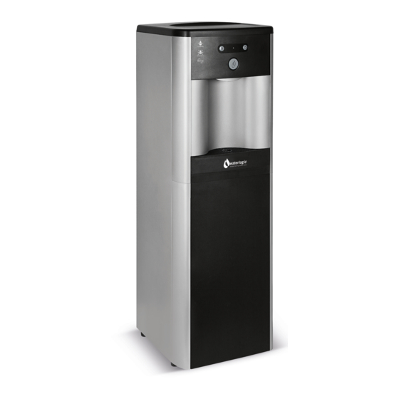
Page 3: Machine Overview
Furthermore, the Activated Carbon process will remove a whole range of contaminants e.g. chlorine and pesticides. There are many kinds of different filter combinations available from Waterlogic to suit local water conditions. Waterlogic 2000IT Technical Manual - Issue B, December 2013... - Page 4 The compressor operates at 220-240V at 50Hz. It uses 65 grams of R134a non- Ozone depleting refrigerant gas for the Free standing model and 40 grams of R134a gas for the Mini Model. Waterlogic 2000IT Technical Manual - Issue B, December 2013...
-
Page 5: Wetted Parts Layout - Hot And Cold
CAUTIONS: • Only competent trained technicians should work on Waterlogic products. • Waterlogic units may weigh over 25KG. We recommend caution when lifting. • Packing materials could present a trip hazard. Keep them off the floor. • Take care not to allow the power lead to get wet. If the lead gets wet it must not be used. -
Page 6: Installation Procedures
To gain access to the screws tilt the ma- chine backward at an angle of 10 degrees. 5. Make the water connection using an installation kit. Waterlogic recommends the use of a pressure reducing valve, a shut off valve and a non-return valve. These should be fitted before the water intake to the machine. - Page 7 • The WL 2000IT must be installed according to the local guidelines. machine. • Waterlogic strongly recommend that a pressure reducing valve is set at 3 bar and a non-return valve be used on all WL 2000IT installations. 11. Check the machine for any water leaks and ensure that all water fittings are se- •...
-
Page 8: Operating Instructions
• Do not dispense water in a stop start style of vending water from selection • (Hold the button continuously until cup is full). • Never try to fill more than one vessel at a time. Waterlogic 2000IT Technical Manual - Issue B, December 2013... -
Page 9: Maintenance And Servicing
SANITISING OR DE-SCALING 4. To remove the Waterlogic filters, twist anti-clockwise and replace with a new Please ensure that you do not accidentally drop sanitiser or de-scaler on any of Waterlogic twist filter, twist clockwise. -
Page 10: Fault Finding
Replace All fault finding procedures must be carried by a technician trained by Waterlogic the hot tank and take the current hot tank back to be bench tested. Reassemble International or their nominated distributor. -
Page 11: Technical Specifications And Warranties
5 - 8°C Hot Water Temp. 85 - 87°C 85 - 87°C Waterlogic has a policy of constant and continual improvement and therefore reserves the right to change specifications without prior notice, other than in the Refrigeration Gas WL2 FW HC... -
Page 12: End Of Life
ROHS Please note: All Waterlogic machines comply with EC Directive (2002/95/EC) on the Restriction BioCote® is an additional line of defence to protect between cleaning routines, it is of the Use of Certain Hazardous Substances in Electrical and Electrical Equipment not a replacement for your normal cleaning and sanitisation processes. -
Page 13: Main Pcb Schematic Diagram Hot And Cold
Main PCB Schematic Diagram Hot and Cold Waterlogic 2000IT Technical Manual - Issue B, December 2013... - Page 14 Silicon Tube 5/16" Stainless Steel Insert for Faucet Faucet HC & CA Natural Faucet O-Ring Faucet Nipple Blue Natural Faucet O-Ring UV Cold Tank Assembly JG LLDPE Tube - Blue 8mm Waterlogic 2000IT Technical Manual - Issue B, December 2013...
-
Page 15: Spare Parts Numbers
Faucet HC & CA Facuet Nipple Blue Stainless Steel Insert for Faucet Natural Faucet O-Ring (Silicon White) Stainless Steel Gauze for Faucet WL2000 Front Panel for Drip Tray Insert Plastic PCB Cover for WL2000 Waterlogic 2000IT Technical Manual - Issue B, December 2013... - Page 16 Power Transformer UV Ballast metal cover UV Lamp Fixing Rubber UV Lamp Retaining Threaded Nut UV Lamp 8W O-ring Quartz Sleeve D310mm for 8W Lamp UV Cold Tank Assembly 4L Wire Condenser Waterlogic 2000IT Technical Manual - Issue B, December 2013...
- Page 17 PCB of WL2000 HC&CA Silicon Button Key Mat WL2000 HC 17 18 19 20 21 WL2000 Front Hatch Panel Charcoal Button Label WL2000 HC&CA WL2000 Drip Tray Grill WL2000 Drip Tray Body Charcoal Waterlogic 2000IT Technical Manual - Issue B, December 2013...
- Page 18 UV Cold Tank Assembly 2L JG Reducing Elbow Connector 5/16" * 1/4" Solenoid Valve DC24V 1000mm JG Reducing Elbow Connector 5/16" * 1/4" Solenoid Valve DC24V 1000mm JG Equal Tee Connector 1/4" Waterlogic 2000IT Technical Manual - Issue B, December 2013...
- Page 19 Speak to a Water Expert USA, Canada and Mexico exportsales@waterlogic.com info@waterlogicusa.com + 353 1 293 1960 + 1 402 884 7212 WLI Trading Ltd. Waterlogic USA, 4141 N. 156th Street, Suite 4, 2nd Floor Beacon Court, Omaha, NE 68116 Sandyford, Dublin 18, Ireland www.waterlogic.com...
Need help?
Do you have a question about the WL2000IT and is the answer not in the manual?
Questions and answers