Advertisement
INSTALLER: Leave this manual with the appliance.
CONSUMER: Retain this manual for future reference.
These instructions are supplementary to the Installation
and Operating Instructions supplied with the fireplace
and should be kept together. Refer to the Installation
and Operating Instructions for proper gas supply, safety
requirements and operating instructions.
030323-20
TC54
TRANQUILITY
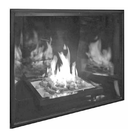
BURNER KIT
INSTRUCTIONS
SKU# 22150049
For TC54 Series D
Fireplaces
SKU# 22150049
100005915
Advertisement
Table of Contents

Summary of Contents for Town & Country Fireplaces 22150049
- Page 1 Operating Instructions supplied with the fireplace and should be kept together. Refer to the Installation and Operating Instructions for proper gas supply, safety requirements and operating instructions. TC54 TRANQUILITY BURNER KIT INSTRUCTIONS SKU# 22150049 For TC54 Series D Fireplaces 030323-20 SKU# 22150049 100005915...
-
Page 2: Package Contents
Package Contents Figure 1: TC54 Tranquility burner kit contents. BURNER ASSEMBLY PEBBLE ASSEMBLY 7lbs SAND LINE COVER, LEFT LINE COVER, RIGHT PKG. TAPERED PLUGS (not shown) 10005915 SKU# 22150049_030323-20... - Page 3 2. Set the burner assembly into the firebox as shown to ease connection setup and right panel installation. (Figure NOTE: If unit is to be converted to Propane, see Propane conversion instructions on page 11 before proceeding. Figure 2: Line covers. Figure 3: Initial burner placement. 100005915 SKU# 22150049 030323-20...
- Page 4 Figure 4: Access cover. 3. Remove access cover to the valve control center from the right side of the firebox (Figure 4). 4. Attach the center supply tube from the “T” and the pilot gas supply tube to the bulk head fitting and tighten (Figure 5).
- Page 5 5. Feed the ignition and sensor wires through the bulkhead plate to the interface module. (Figure 6). 6. Attach the ignition and sensor wires to the interface module as shown in (Figure 7). Flame sensor wire (white) Ignition wire (red) Interface module Figure 7: Interface module. 100005915 SKU# 22150049 030323-20...
- Page 6 Figure 8: Access cover. 7. Re-install the access panel in the right side of the firebox (Figure 8). 8. Install right side panel as per panel installation instructions and finalize setting burner assembly into the unit (Figure 9). Figure 9: Burner assembly installed. 10005915 SKU# 22150049_030323-20...
- Page 7 9. Slide the line covers out from under the burner tray and slip the tab into the slot in the assembly base. (Figure 10). 10. Place tapered plugs into all burner ports to prevent sand from entering the burners.(Figure 11). Figure 11: Tapered plugs in ports. 100005915 SKU# 22150049 030323-20...
- Page 8 CAUTION: Before pouring sand ensure all connections and adjustments are made. Removing sand is very difficult. Figure 12: Sand placement. 11. Pour sand evenly over tray and burners using the entire contents. Use caution not to let sand enter pilot locations. (Figure 12). 12.
- Page 9 14). 14. Place four trim rocks, approx. 2” dia., in spaces between the pebble assemblies to fill the gaps. Do not place rocks on top of the assemblies.(Figure 15 & 16). Figure 15: Placing trim rocks. 100005915 SKU# 22150049 030323-20...
- Page 10 Figure 16: Placing trim rocks. 15. Place the remaining four trim rocks at desired locations around the pebble assemblies. Do not place rocks on top of the assemblies.(Figure 16). 10005915 SKU# 22150049_030323-20...
-
Page 11: Propane Conversion
4. Apply a small amount of pipe joint compound to the threads of the propane burner orifices marked “LD” to ensure a good seal, before screwing it into the manifold. Figure 18: Remove NG orifices. Install LP orifces. 100005915 SKU# 22150049 030323-20... - Page 12 This appliance was converted to propane gas Kit Number 5052.52001-B Company Address The above accepts the responsibility that this conversion has been properly performed. Figure 19: Adjust shutters and remove pilot. 5. Open primary air shutters fully. Remove the pilot from the burner. (Figure 19) 6.
-
Page 13: Gas Pressure Check
Natural Gas Propane Min. Pressure 5.0" WC 12.5" WC (For purpose of input adjustment) Max. Pressure 13.9" WC 13.9" WC Manifold Pressure Maximum 3.5" WC 10" WC Minimum 1.6" WC 6.4" WC Figure 23: Pressure adjustment. 100005915 SKU# 22150049 030323-20... -
Page 14: Burner Flame Adjustment
Burner Flame Adjustment The air shutter on the burner tube controls the primary combustion air to the gas burner. The shutter should be set to fully closed for natural gas or fully open for propane. See Figure 24 for proper flame pattern. -
Page 15: Parts Diagram
Parts Diagram (WHEN ORDERING, INCLUDE PART NUMBER WITH DESCRIPTION) ITEM .... DESCRIPTION ..............PART NO. #1....TC54 TRANQUILITY BURNER KIT ........22150049 #2....BURNER ................80001212 #3....PILOT ASSEMBLY, CONVERTIBLE ........80000525 #4....ORIFICE, NG marked “ND” (2 Required) ......80002042 #5.... - Page 16 © 2023 Copyright Pacific Energy Fireplace Products LTD Reproduction, adaptation, or translation without prior written permission is prohibited, except as allowed under the copyright laws. For technical support, please contact your retailer. Web site: www.townandcountryfireplaces.net 2975 Allenby Rd., Duncan, BC V9L 6V8 Printed in Canada...


Need help?
Do you have a question about the 22150049 and is the answer not in the manual?
Questions and answers