Advertisement
Quick Links
INSTALLER: Leave this manual with the appliance.
CONSUMER: Retain this manual for future reference.
These instructions are supplementary to the Installation
and Operating Instructions supplied with the fireplace
and should be kept together. Refer to the Installation
and Operating Instructions for proper gas supply, safety
requirements and operating instructions.
Visit www.townandcountryfireplaces.net for the most recent version of this manual
230223-24
SKU# 22150012(Brown) &
22150020(Black)
For TC36D & TC36D Arch
Series D
SKU# 22150012 &22150020
TC36D
TRANQUILITY
BURNER KIT
INSTRUCTIONS
100005911
Advertisement

Related Manuals for Town & Country Fireplaces 22150012


Summary of Contents for Town & Country Fireplaces 22150012
- Page 1 Operating Instructions for proper gas supply, safety requirements and operating instructions. TC36D TRANQUILITY BURNER KIT INSTRUCTIONS SKU# 22150012(Brown) & 22150020(Black) For TC36D & TC36D Arch Series D Visit www.townandcountryfireplaces.net for the most recent version of this manual 230223-24 SKU# 22150012 &22150020...
-
Page 2: Contents Of Package
A. Burner assembly (including pilot & gas lines) B. Panel, base (attached to burner assembly). C. Pebble assembly D. Hardware - tapered plugs, screws, brush, panel clips. E. Side cover - left hand side. F. 2.2 lbs Sand G. Side cover (right hand side) SKU# 22150012/22150020 230223-24... - Page 3 1. Remove floor shield (2 screws) and discard the shield. Use screws to plug vacant holes. 2. Plug any other vacant holes in the bottom of the firebox with 1/2” screws, as they are not required to attach this style of burner (Figure 3). Figure 3: Removing floor shield. SKU# 22150012/22150020 230223-24...
- Page 4 Figure 5: Access cover to valve control center. Figure 6: Flex line bent to shape. SKU# 22150012/22150020 230223-24...
- Page 5 7. Remove the two lower outside screws from the Air Channel as indicated in Figure 9. The lower panel will be attached to the rear wall of the firebox using the two screws just removed. Figure 9: Air channel. SKU# 22150012/22150020 230223-24...
- Page 6 (Figure 10). 9. Position the burner tray assembly into the firebox and against the lower rear panel (Figure 11). Rear Panel Burner Assembly Figure 11: Lower rear panel and burner assembly. SKU# 22150012/22150020 230223-24...
- Page 7 (Figure 12). Ensure that there are no leaks. 11. Feed the ignition and sensor wires through the bulkhead plate and gasket to the firebox (Figure 13). Ignition and sensor wires Bulkhead plate Figure 13: Ignition and sensor wires routing. SKU# 22150012/22150020 230223-24...
- Page 8 13. Once the gas and electrical lines are connected to the bulkhead and the interface module, rein- stall the valve control center’s access cover (Figure 5 on page 4). The panels are now ready to be installed. Figure 15: Lower rear panel and burner assembly. SKU# 22150012/22150020 230223-24...
- Page 9 15. The right hand side panel has a cut out which will t over the side cover. The correct orientation of the upper rear panel has the two insulation retaining clips on the rear of the panel at the top (both Figure 17). Figure 17: Panel retainer removal. SKU# 22150012/22150020 230223-24...
- Page 10 If upper rear panel seems too loose once installed, remove panel, bend the tabs forward and try again. Figure 19: Lower rear panel and burner assembly. SKU# 22150012/22150020 230223-24...
- Page 11 21. Reinsert the two screws previously removed from the panel retainer but do not tighten. Reinstall the panel retainer and fit slots to hook onto the two screws. Tighten screws (Figure 21). Figure 21: Panel retainer reinstalled. SKU# 22150012/22150020 230223-24...
- Page 12 24. Place sand in tray. Use supplied brush to spread and level the sand to just below the top of raised burner ports. Gently blow excess sand from around ports (Figure 24). Figure 23: Inserting tapered plugs. SKU# 22150012/22150020 230223-24...
- Page 13 26. Remove pebble assembly from packaging by placing hand on top and tipping upside down. Note that the rock in the lower right is hollow underneath and will fit over top of the pilot assembly (Figure 25). Figure 25: Tranquility rock set SKU# 22150012/22150020 230223-24...
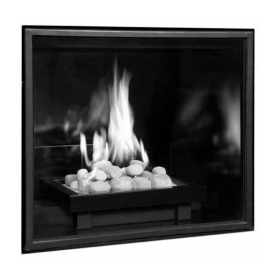
- Page 14 27. Gently place pebble assembly onto sand base aligning 3 holes in the bottom of the rock set to the 3 pins located on the burner tray (Figure 26). 28. Install glass door. Unit is ready for lighting. Figure 27: TC36 Tranquility rock set in place. SKU# 22150012/22150020 230223-24...
-
Page 15: Propane Conversion
If the unit is to be used on propane convert as follows using the components supplied with this burner: Figure 28: Access panel. 1. Remove rock set and sand if present. 2. Remove right hand side panel if present. 3. Remove all 10 screws from the Valve control center panel (Figure 28). SKU# 22150012/22150020 230223-24... - Page 16 Figure 30: Disconnecting ame sensor and ignition wires at interface. 5. Disconnect the ame sensor wire and the ignition wire from the interface module (Figure 30) and withdraw the wires back through the bulkhead plate and into the rebox area. SKU# 22150012/22150020 230223-24...
- Page 17 (Figure 33). Apply a small amount of pipe joint compound to the threads of the propane burner orifice to ensure a good seal, before screwing it into the fitting. Figure 33: Orifice. Figure 34: Air shutter fully closed for natural gas. SKU# 22150012/22150020 230223-24...
- Page 18 10. Remove the 2 screws holding the pilot assembly in place with a short screwdriver (Figure 36). 11. With a 7/16” wrench, loosen the pilot head on the pilot assembly using a wrench to hold the bracket steady (Figure 37). Figure 37: Loosening pilot shield. SKU# 22150012/22150020 230223-24...
- Page 19 5052.52001-B Company Address The above accepts the responsibility that this conversion has been properly performed. Figure 40: Removing pilot assembly. For complete valve conversion installation instructions, refer to the instruction book included in the SIT conversion kit. SKU# 22150012/22150020 230223-24...
-
Page 20: Gas Pressure Check
Min. Pressure 5.0" WC 12.5" WC PRESSURE (For purpose of input adjustment) Max. Pressure 13.9" WC 13.9" WC MANIFOLD Manifold Pressure PRESSURE Maximum 3.5" WC 10" WC Minimum 1.6" WC 6.4" WC Figure 43: Gas test ports. SKU# 22150012/22150020 230223-24... - Page 21 Proper air shutter setting is required, fully closed for natural gas and half open for propane. The flame should be just orange and “lazy” . It should NEVER be set to create sooting on internal parts and window glass. SKU# 22150012/22150020 230223-24...
-
Page 22: Parts Diagram
1d ............LINE COVER, LT #6 ORIFICE NG 1e .............TRANQUILITY LEG #7 PROPANE CONVERSION KIT (not shown) 1f ..............FLOOR PAN #8 SAND (not shown) 1g ...........TAPPED 1/8-27 NPT 1h ............LINE COVER, RT 1i ..........BURNER INLET TUBE 1j ............. CURB CLAMP SKU# 22150012/22150020 230223-24... - Page 23 SKU# 22150012/22150020 230223-24...
- Page 24 © 2017 Copyright Pacic Energy Fireplace Products LTD Reproduction, adaptation, or translation without prior written permission is prohibited, except as allowed under the copyright laws. TFor technical support, please contact your retailer. Web site: www.townandcountryfireplaces.net 2975 Allenby Rd., Duncan, BC V9L 6V8 Printed in Canada...
Need help?
Do you have a question about the 22150012 and is the answer not in the manual?
Questions and answers