Advertisement
INSTALLER: Leave this manual with the appliance.
CONSUMER: Retain this manual for future reference.
These instructions are supplementary to the Installation
and Operating Instructions supplied with the fireplace
and should be kept together. Refer to the Installation
and Operating Instructions for proper gas supply, safety
requirements and operating instructions.
140322-12
TC36 ST, Chalet Burner Kit, D/D2
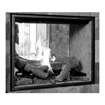
TC36ST SEE-THRU
CHALET
BURNER KIT
INSTRUCTIONS
PART# 22150055
For TC36ST SEE-THRU
FIREPLACES
Series D/D2
100005514
Advertisement
Table of Contents

Summary of Contents for Town & Country Fireplaces 22150055
- Page 1 Refer to the Installation and Operating Instructions for proper gas supply, safety requirements and operating instructions. TC36ST SEE-THRU CHALET BURNER KIT INSTRUCTIONS PART# 22150055 For TC36ST SEE-THRU FIREPLACES Series D/D2 140322-12 TC36 ST, Chalet Burner Kit, D/D2 100005514...
-
Page 2: Package Contents
Package Contents • BURNER/GRATE ASSEMBLY • 11 PCS LOG SET • PILOT ASSEMBLY • GAS FLEX LINE • 2 EMBER MATERIAL • HARDWARE PACKAGE Burner/Grate Installation In these instructions the right and left sides of the fireplace are refer- Fig. # 1 enced during the installation process. -
Page 3: Propane Conversion
Propane Conversion If the unit is to be used on propane, convert as follows using the components supplied with this fireplace: WARNING This conversion kit shall be installed by a qualified service agency in accordance with the manufacturer's instructions and all applicable codes and requirements of the authority having jurisdiction. - Page 4 4. Remove the 2 front screws holding the burner tray in place and slide tray Fig. # 4 sideways to access burner orifice. (Fig. #4) 5. Using a 1/2” wrench, undo the natural gas burner orifice, (marked #32). (Fig. #5) 6.
-
Page 5: Interface Module
2 SCREWS Fig. # 9 Fig. # 10 BULKHEAD PLATE INTERFACE FLAME SENSOR IGNITION MODULE WIRE (WHITE) WIRE (RED) 13. Secure the electrical bulkhead plate (Fig.#9) and gasket to the firebox. (2 screws) Attach the ignition and sensor wires to the module. -
Page 6: Gas Pressure Check
Gas Pressure Check Note: To test the gas pressure, turn off the gas supply before removing the blank- ing plug from the supply pressure test port or manifold pressure test port. Verify gas pressures with the fireplace lit and on the highest setting. Fig. - Page 7 Ember Material Two large bags of ember material are shipped with the fireplace and need to be Fig. # 15 installed to ensure optimum performance and flame appearance. Pull apart the material into ember size pieces (approximately 1” squares) and gently place them into the burner pan.
-
Page 8: Left Log Placement
Step 3 Step 4 LEFT LOG PLACEMENT LEFT END LOG PLACEMENT 3. Install the left log onto the grate straddling the grate 4. Install the left end log on the floor near the left leg of as shown. the grate as shown. VALVE SIDE VALVE SIDE VALVE SIDE... - Page 9 Step 7 Step 8 RIGHT LOG PLACEMENT LEFT LOG PLACEMENT VALVE SIDE VALVE SIDE VALVE SIDE VALVE SIDE Step 9 Step 10 RIGHT END LEFT LOG PLACEMENT LEFT END LOG PLACEMENT VALVE SIDE VALVE SIDE VALVE SIDE VALVE SIDE Step 11 CENTER FLOOR LOG PLACEMENT Note: Improper placement of logs will create soot on internal parts and glass.
-
Page 10: Burner Flame Adjustment
Burner Flame Adjustment The air shutter on the burner tube controls the PRIMARY AIR SHUTTERS primary combustion air to the gas burner and is pre-set closed at the factory for natural gas fuel. Some adjustment may be necessary to Fig. # 16 obtain desired flame and to eliminate carbon deposits. -
Page 11: Replacement Parts
Replacement Parts ITEM ..DESCRIPTION ........PART NO. ITEM ..DESCRIPTION ........PART NO. 1.... LOG GRATE ......TC36.9381WELD 14 ... 1/4” FLEX COMPRESSION ......5019.225 2.... BURNER TRAY SUPPORT SHIELD ..9369.001 15 ... 1/2” FLEX FLARE CONNECTION ....5019.223 3.... BURNER TRAY, FR ....TC36.9370FWELD 16 ... - Page 12 © 2015 Copyright Pacific Energy Fireplace Products LTD Reproduction, adaptation, or translation without prior written permission is prohibited, except as allowed under the copyright laws. For technical support, please contact your retailer. www.townandcountryfireplaces.net 2975 Allenby Rd., Duncan, BC V9L 6V8 Printed in Canada...


Need help?
Do you have a question about the 22150055 and is the answer not in the manual?
Questions and answers