Table of Contents
Advertisement
Quick Links
ISTRUZIONI PER L'INSTALLAZIONE E LA MANUTENZIONE
Gentile Cliente,
metta in funzione la sua nuova caldaia entro 30gg dalla data di installazione da personale
professionalmente qualificato. Potrà così beneficiare sia della garanzia legale, sia della
garanzia convenzionale Sime che trova alla fine di questo manuale.
Fonderie SIME S.p.A
1R HE 9 ErP
NL
IT
DE
ES
GR
ENG
FR
Cod. 6276078 - 12/2016
Advertisement
Table of Contents

Related Manuals for Sime 1R HE 9 ErP


Summary of Contents for Sime 1R HE 9 ErP
- Page 1 30gg dalla data di installazione da personale professionalmente qualificato. Potrà così beneficiare sia della garanzia legale, sia della garanzia convenzionale Sime che trova alla fine di questo manuale. Fonderie SIME S.p.A Cod. 6276078 - 12/2016...
-
Page 2: Table Of Contents
CONTENTS BOILER DESCRIPTION 1.1 INTRODUCTION ............................... 24 1.2 DIMENSIONAL DETAILS 1.3 TECHNICAL FEATURES ............................ 25 1.4 FUNCTIONAL DIAGRAM 1.5 COMPATIBLE BURNERS ............................ 26 1.6 CONNECTION OF CONDENSATION WATER TRAP .................... 27 INSTALLATION 2.1 BOILER ROOM ................................. 28 2.2 BOILER ROOM DIMENSIONS 2.3 CONNECTING UP SYSTEM 2.4 CONNECTING UP FLUE 2.5 ELECTRICAL CONNECTION USE AND MAINTENANCE 3.1 COMMISSIONING THE BOILER . -
Page 3: Boiler Description
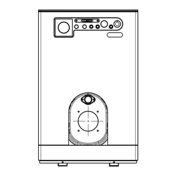
BOILER DESCRIPTION 1.1 INTRODUCTION boilers condensing they use light oil and economical performance. have a perfectly balanced combustion The new 1R HE 9 ErP series of cast iron with a very high thermal efficiency for 1.2 DI M EN S IO N AL DETAILS (fig. 1) 1410 1R HE 9 ErP M C.H. flow G 1” (UNI-ISO 228/1) R C.H. return G 1” (UNI-ISO 228/1) Fig. 1 1.2.1 Technical data plate (fig. 2) MODEL SERIAL NUMBER CODE YEAR OF CONSTRUCTION DIRECTIVE OF REFERENCE... -
Page 4: Technical Features
1.3 TECHNICAL FEATURES 1R HE 9 ErP Output 80-60°C 74.5 50-30°C 78.7 Input 78.0 Useful efficiency measured at 100% 80-60°C 95.5 50-30°C 100.9 Useful efficiency measured at 30% 103.0 PIN number 1312CR194R Type B23P Sections n° Maximum water head bar (kPa) 4 (392) Water content 37.7 Smokes loss of head mbar (kPa) 0.46 (0.0450) Combustion chamber pressure mbar (kPa) 0.98 (0.0960) Suggested chimney depression mbar (kPa) 0.15 (0.0147) Smokes temperature 80-60°C °C 88.1 50-30°C °C... -
Page 5: Compatible Burners
1.5.1 Burners assembly (fig. 4) The boiler door details is shown in figure 3/a for burner mounting. The burners must be regulated such that the CO value is that indicated in point Fig. 4 1.3, with a tolerance of ± 5%. 1.5.2 Permanent feeding burners Model Code Nozzle Atomising Pump Class Adsorbed power Type ø angle pressure NOx consumption bar 1R HE 9 ErP SIME MACK 4 8099010 DELEVAN 0,75 60°W 11,0... -
Page 6: Connection Of Condensation Water Trap
1.6 CONNECTION OF CONDENSATION WATER TRAP (fig. 5) The drip board and its water trap must be connected to a civil drain through a pipe (ø 25) with a slope of at least 5 mm per metre to ensure drainage of conden- sation water. The plastic pipes normally used for civil drains are the only type of pipe which is appropriate for conveying condensation to the building’s sewer pipes. 1 Drain hose 2 Condensate drain tap Fig. 5... -
Page 7: Installation
INSTALLATION 2.1 BOILER ROOM stem. an internal section 10% greater than that of the boiler union; The boiler room should feature all the – Should it be necessary to empty the characteristics required by standards system either partially or totally. – the useful section of the flue must governing liquid fuel heating systems. conform to the following formula: S = K 2.3.3... - Page 8 NOTE: The brown (capped off) cable has to be exclusively used in case of permanent feeding burners (type B1). B1 Permanent Feeding Burner (optional) Line TA Room stat Neutral OP Programmer’s clock (optional) Main switch TS Safety stat NO T E: TC Boiler stat - When a room stat (TA) is to be fitted remove the link SA Green voltage LED between terminal 4 and 5 on the connector plug.
-
Page 9: Use And Maintenance
USE AND MAINTENANCE WARNINGS – In case of failure or malfunction of the equipment, contact authorised technical staff. – For safety reasons, the User cannot access the internal parts of the appliance. All operations involving the removal of protections or otherwise the access to dan- gerous parts of the appliance must be performed by qualified personnel. – The appliance can be used by children under 8 years and by persons with redu- ced physical, sensory or mental capabilities, or lack of experience or knowledge, provided they are under supervision or after they have been given instructions concerning the safe handling of the appliance and the understanding of the dan- gers inherent to it. Never let children play with the appliance. Children without supervision must not carry out cleaning and maintenance meant to be carried out by the user. 3.1 COMMISSIONING THE BOILER When commissioning the boiler always make sure that: – the system has been filled with water and adequately vented; – the flow and return valves are fully open; – the flue and chimney are free from obstructions;... -
Page 10: Regular Cleaning
the presence of voltage.The burner will start. 60ϒ C 3.2.2 Boiler stat (fig. 8) 60ϒ C Turn the boiler stat knob to a tempera- ture no lower than 60°C. The set temperature value can be checked on the thermometer. 3.2.3 Safety stat (fig. 9) The manually reset safety stat trips to switch-off the burners immediately when the boiler temperature exceeds 100°C. To restart the boiler, unscrew the black cover and press the button underneath. -
Page 11: Frost Potection
The boiler gets dirty easily system, the function of the circulation the equipment MUST BE RECYCLED in line – Check the burner regulator (smoke pumps. with current legislation. analysis), the fuel quantity, the flue – Check the load pressure of the appli- obstruction and the cleanness of the ance, the efficiency of the expansion IT MUST NOT be disposed of together with air duct of the burner (dust). tanks and the valve calibration. urban waste.
Need help?
Do you have a question about the 1R HE 9 ErP and is the answer not in the manual?
Questions and answers