Sime Murelle Equipe 100 BOX ErP Manual
Hide thumbs
Also See for Murelle Equipe 100 BOX ErP:
- Original instructions manual (73 pages) ,
- User, installation and servicing instructions (56 pages) ,
- Manual (39 pages)
Advertisement
Available languages
Available languages
Quick Links
Advertisement

Related Manuals for Sime Murelle Equipe 100 BOX ErP


Summary of Contents for Sime Murelle Equipe 100 BOX ErP
- Page 1 MURELLE EQUIPE 100-150 BOX ErP Fonderie SIME S.p.A Cod. 6322833 - 03/2016...
- Page 3 La FONDERIE SIME S.p.A. afincada en Via Garbo 27 - Legnago (VR) – Italy, declara que sus calderas de agua caliente, marcadas CE conforme a la Directiva Gas 90/396/CEE y equipadas con termostato de seguridad aju- stado para un máximo de 110°C, están excluidas del campo de aplicación de la Directiva PED 97/23/CEE ya que...
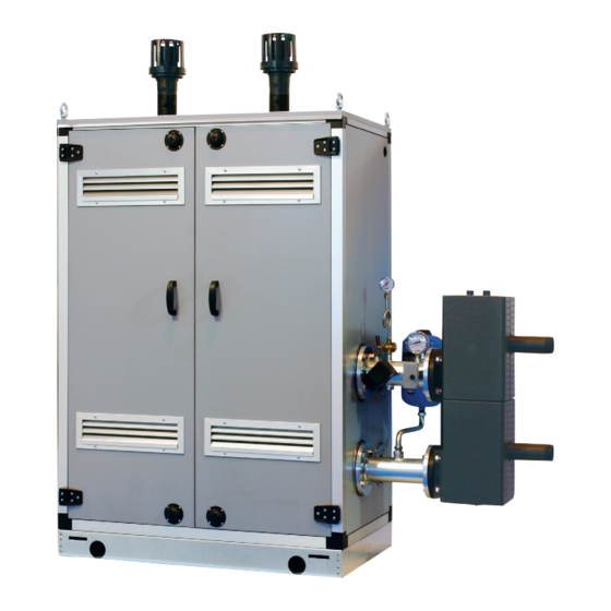
- Page 4 100-150 BOX ErP son aparatos de con- para el funcionamiento individual o en DIMENSIONES MÓDULOS 1.2. 1 “MURELLE EQUIPE 100 BOX ErP” 1775 1100 CONEXIONES M Ida instalación G 2” (UNI - ISO 7/1) Retorno instalación G 2” (UNI - ISO 7/1) Gas (Brida PN6-DN50) S3 Descarga agua de condensación ø...
- Page 5 1.2.2 “MURELLE EQUIPE 150 BOX ErP” 1100 (Murelle Equipe 100 BOX ErP) 1730 CONEXIONES M Ida instalación G 2” (UNI - ISO 7/1) Retorno instalación G 2” (UNI - ISO 7/1) Gas (Brida PN6-DN50) S3 Descarga agua de condensación ø 40 NOTA: Es obligatorio montar un separador hidráulico o intercambiador de placas.
- Page 6 DATOS TÉCNICOS MURELLE EQUIPE 100 BOX ErP 150 BOX ErP Generadores con potencia térmica nominal 46,7 kW n° Potencia térmica Nominal (80-60°C) (Pn max) 93,4 140, 1 Nominal (50-30°C) (Pn max) 102,0 153,0 Mínima (80-60°C) (Pn min) Mínima (50-30°C) (Pn min) 10,5 10,5 Caudal térmico (*)
- Page 7 ESQUEMA FUNCIONAL (fig. 2) 19 20 LEYENDA 1 Sonda ida de cascada (SMC) 2 Compensador hidráulico 3 ---------- 5 Sifón descarga agua de condensación 6 Válvula gas 7 ---------- 8 Ventilador 9 Sonda ida calefacción (SM) 10 Termostato seguridad 100°C 11 Sonda humos (SF) 12 Intercambiador primario 14 Sonda retorno calefacción (SR)
- Page 8 COMPONENTES PRINCIPALES (fig. 3) Codice/Code 8111227 Modello/Model MURELLE EQUIPE 100 BOX ErP Matricola/Serial n. 9999999999 PAR 1 = 6 (G20) / 14 (G31) PAR 2 = 9 LEGENDA 1 Colector retorno instalación 2 Grifo gas 3 Colector ida instalación 4 Válvula gas 5 Ventilador 6 Termostato seguridad 100°C...
- Page 9 INSTALACIÓN La instalación debe considerarse fija y debe A parte hay disponibles: el montaje de las descarga de humos para ser efectuada exclusivamente por empre- – Kit tubos de conexión separador hidráuli- instalaciones internas o externas, ver los sas especializadas y cualificadas, cumplien- co cód.
- Page 10 2.2.2 Al exterior del edificio debe estar conectada con un embudo de Sólo las tuberías de plástico de los nor- recolección para encauzar la eventual males desagües son idóneas para encau- Los módulos térmicos MURELLE EQUIPE purga en caso de que dicha válvula actúe. zar el agua de condensación hacia la red 100-150 BOX ErP se pueden instalar tam- ATENCIÓN: No efectuar el lavado de la...
- Page 11 Para este tipo de instalación hacer referen- la salida a la izquierda simplemente girando cos en caso de instalación exterior. ø D MODELO Murelle Equipe 100 BOX ErP 2020 Murelle Equipe 150 BOX ErP 2055 Fig. 6...
- Page 12 KIT TUBOS DE CONEXIÓN DEL SEPARADOR HIDRÁULICO (fig. 7) SIME proporciona el kit tubos de conexión del separador hidráulico cód. 8101534 para la instalación con los ataques en el lado izquierdo. El kit tiene la siguiente composición (fig, 7): – Tronco con brida de impulsión instala- ción cód.
- Page 13 CONNETTORE CABLATO (cod. 6319173) WIRED CONNECTOR (cod 6319173) DIP SWITCH GESTIONE IN MODBUS MODBUS MANAGEMENT 1 2 3 COMUNICAZIONE MODBUS MODBUS COMMUNICATION TABELLA PAR 17 INST/ Tab. PAR 17 INST CONFIGURACIÓN DE LOS PARÁMETROS DEL INSTALADOR: PAR 17 INST N° Bit Dati Baud Rate Parità...
- Page 14 TABELLA DELLE VARIABILI MODBUS / MODBUS BOILER VARIABLES LIST Descrizione / Function Variable description Digital variables (COILS) Boiler CH Enable/Request D R/W Richiesta riscaldamento zona 1 Request CH zone 1 Boiler DHW Enable D R/W Abilitazione preparazione ACS Enable DHW preparation Boiler Water Filling Function D R/W Non usato...
- Page 15 2. 1 0 SEPARADOR HIDRÁULICO El separador hidráulico viene suministrado a parte en un kit cód. 8101550 completo de juntas, tuercas y tornillos de fijación (fig. 9). El montaje del separador hidráulico es obligatorio para los módulos 100-150 BOX ErP. ATENCIÓN: Es posible introducir el separa- dor hidráulico en un contenedor de protec- ción cód.
- Page 16 ELÉCTRICA sión monofásica 230V - 50Hz pasando por un interruptor general protegido por fusi- NOTA: La SIME rehúsa cualquier respon- Cada módulo tiene cable eléctrico de ali- bles con distancia entre los contactos de sabilidad ante daños a personas o cosas mentación que, si debe ser reemplazado,...
- Page 17 2. 1 1.2 Conexión eléctrica de los módulos en secuencia/cascada (fig. 11/a) LEYENDA Línea Neutral Sonda temperatura externa Sonda ida de cascada RS-485 Ficha gestión en cascada NOTA: La sonda de temperatura exterior (SE) se debe conectar a la caldera MASTER y la sonda de impulsión de cascada (SMC) a la caldera SLAVE 1 Las sondas SE, SMC y el cable de conexión de las placas RS-485 se incluyen con los móduos en el kit de sondas cód.
- Page 18 Están activas Debe ser utilizada exclusivamente con el kit de progra- las funciones de protección. mación de SIME y sólo por personal autorizado. No TECLA MODALIDAD VERANO conectar otros dispositivos electrónicos (cámaras foto- Si se pulsa esta tecla, la caldera funciona sólo gráficas, teléfonos, mp3, etc.).
- Page 19 ACCESO A LA INFORMACIÓN PARA EL INSTALADOR Para acceder a la información para el instalador, pulsar la tecla (3 fig. 12). Cada vez que se pulsa la tecla se pasa a la información siguien- te. Si la tecla no se pulsa, el sistema sale automáticamente de la función. Si no está conectada ninguna ficha de expansión (ZONA MIX o INSOL) no se mostrarán las relativas informaciones.
- Page 20 18. Visualización valor sonda retorno calefacción (SR) 29. Visualización mando de cierre de las válvulas con tarjeta ZONA MIX 2 (respectivamente ON y OFF) 18. Visualizzazione valore sonda ritorno riscaldamento (SR) 29. Visualizzazione comando chiusura valvola con schedino ZONA MIX 2 (rispettivamente ON e OFF) 19.
- Page 21 0 = Inhabilitado La visualización estándar vuelve automáti- 1 = Habilitado camente después de 60 segundos, o al pul- Asignación canales SIME HOME 0 = No asignado sar una de las teclas de mando (2 fig. 12) 1 = Circuito 1 excluido la tecla RESET.
- Page 22 CALDERA PAR 2 PARÁMETROS PARA EL INSTALADOR Instantánea con valv. desviadora e indicador de flujo TARJETA EXPANSIÓN Instantánea con valv. desviadora, indicador de flujo y combinación solar PAR DESCRIPCIÓN RANGO UNIDAD PASO VALOR DE MEDIDA PREDET. Hervidor remoto con Número de tarjetas de expansión 0 ...
- Page 23 El electrodo está conectado a masa o – Interfaz con los siguientes sistemas elec- ENCENDIDO ELECTRONICO muy desgastado: es necesario sustituirlo. trónicos: control remoto SIME HOME, La tarjeta electrónica está averiada. termorregulación RVS, conexión a una El encendido y la detección de llama se con- tarjeta de gestión de una zona de mezcla...
- Page 24 ALTURA DE ELEVACION de calefacción está representada, en fun- terminado (parámetro del instalador PAR DISPONIBLE EN ción de la capacidad, del gráfico de la fig. 14. 13 = Au). LA INSTALACION (fig. 14) La velocidad de la bomba instalación modu- La prevalencia residual para la instalación lante se ha configurado con un valor prede- 1000...
- Page 25 Esta operación debe necesariamente ser ejecutada por personal autorizado y con 3) Buscar los valores de CO a la poten- componentes originales Sime, so pena de cia máx. indicados a continuación, aju- pérdida de vigencia de la garantía. stando el parcializador (5 fig. 16):...
- Page 26 instalación y de uso. En cualquier caso es conveniente hacer ejecutar un control anual a personal técnico autorizado. Durante las operaciones de mantenimien- to se debe comprobar que el gotero sifón esté lleno de agua(verificación necesaria especialmente cuando hace mucho tiem- po que no se utiliza el generador).
- Page 27 4.5.3 Diagnosis y remedio bomba instalación alta eficiencia (fig. 22/a) LED diagnosis y remedio Color Led Significado Diagnóstico Causas Remedio Verde continua Funcionamiento Funcionamiento normal Funcionamiento normal normal de la bomba o se encuentra de frente a un fenómeno que afecta un poco su funcionamiento Rojo/verde Anomalía (bomba...
- Page 28 ANOMALÍAS DE de la llama, la caldera se para y en el FUNCIONAMIENTO display aparece la anomalía ALL 06. Pulsar la tecla del panel de man- Pulsar la tecla del panel de man- dos (2) para volver a activar la caldera. Cuando se presenta una anomalía de fun- dos (2) para volver a activar la caldera.
- Page 29 Cuando la sonda anti-hielo sifón (SA) o encendido. Durante dicha anomalía la caldera sigue sonda calentador L.2000 (SB) está funcionando normalmente. abierta o en cortocircuito, en el display se visualiza la anomalía ALL 10. – INTERVENCIÓN TERMOSTATO DE SEGURIDAD SEGUNDA ZONA MEZ- CLADA “ALL 22”...
- Page 30 Fig. 23/26 da (sonda de impulsión de cascada ALL Fig. 23/22 31) la pantalla del mando remoto SIME HOME muestra la alarma 70. Compro- – ANOMALÍA COMUNICACIÓN FICHA bar la anomalía en la cascada.
- Page 31 PARA EL USUARIO ADVERTENCIAS – Desactivar el equipo en caso de rotura y/o mal funcionamiento, absteniéndose de realizar cualquier intento de repa- ración o de intervención directa. Para esto dirigirse exclusivamente a personale técnico autorizado . – La instalación de la caldera y cualquier intervención de asistencia o mantenimiento deben ser ejecutadas por perso- nal calificado conforme a la norma CEI 64-8.
- Page 32 zonas). El display se presenta como indica la figura. Modificar los valores con las teclas . La visualización están- dar vuelve al pulsar la tecla o al cabo de 10 segundos si no se pulsa ninguna tecla. REGULACIÓN CON SONDA EXTERNA CONECTADA (fig.
- Page 33 Solicitar la intervención de personal técnico autorizado. – ALL 70 y ALL 71 Estas alarmas se muestran en la pan- talla del mando remoto SIME HOME. Solicitar la intervención de personal técnico autorizado. LED VERDE BOMBA INSTALACIÓN ALTA EFICIENCIA (fig. 28) Si falta la señal LED o cambia el color (rojo-...
- Page 34 NOTE...
- Page 35 – Discharge any air in the gas pipes by using the pressure escape on the gas valve. FONDERIE SIME S.p.A. located in Via Garbo 27 - Legnago (VR) - Italy declares that its hot water boilers, CE appro- ved according to Gas Directive 90/396/CEE and equipped with safety thermostat calibrated to maximum 110°C, are exempt from PED Directive 97/23/CEE application field because they meet the requisites foreseen in arti- cle 1 comma 3.6 therein.
- Page 36 MURELE EQUIPE 100-150 BOX ErP are and easy to assemble, designed to work DIMENSIONS MODULES 1.2. 1 “MURELLE EQUIPE 100 BOX ErP” 1775 1100 FIXTURES M System supply G 2” (UNI - ISO 7/1) System return G 2” (UNI - ISO 7/1) Gas (Flange PN6-DN50) S3 Condensation drain ø...
- Page 37 1.2.2 “MURELLE EQUIPE 150 BOX ErP” 1100 (Murelle Equipe 100 BOX ErP) 1730 FIXTURES M System supply G 2” (UNI - ISO 7/1) System return G 2” (UNI - ISO 7/1) Gas (Flange PN6-DN50) S3 Condensation drain ø 40 NOTE: Assembly of a hydraulic separator or plate exchanger is also mandatory. The hydraulic separator is supplied with modu- les in a kit code 8101550 and the tubes connecting the hydraulic separator in the kit code 8101534.
- Page 38 TECHNICAL SPECIFICATIONS MURELLE EQUIPE 100 BOX ErP 150 BOX ErP Generators with a heat output kW 46.7 n° Heat output Nominal (80-60°C) (Pn max) 93.4 140. 1 Nominal (50-30°C) (Pn max) 102.0 153.0 Minimum (80-60°C) (Pn min) Minimum (50-30°C) (Pn min) 10.5 10.5 Heat input (*)
- Page 39 OPERATING DIAGRAM 19 20 1 Cascade supply probe (SMC) 2 Hydraulic compensator 3 ---------- 5 Condensation drain siphon 6 Gas valve 7 ---------- 8 Fan 9 Heating supply probe (SM) 10 Safety thermostat 100°C 11 Sensor fumes (SF) 12 Primary exchanger 14 Heating return probe (SR) 15 Pressure transducer 17 Check valve...
- Page 40 MAIN COMPONENTS Codice/Code 8111227 Modello/Model MURELLE EQUIPE 100 BOX ErP Matricola/Serial n. 9999999999 PAR 1 = 6 (G20) / 14 (G31) PAR 2 = 9 1 System return manifold 2 Gas tap 3 System supply manifold 4 Gas valve 5 Fan 6 Safety thermostat 100°C...
- Page 41 INSTALLATION Installation is permanent and must exclusi- – Polypropylene exhaust manifold kit for least 3.000 sq. cm or 5.000 sq. cm for vely be performed by specialised and quali- indoor installation (purposely treated to gas with density over 0.8, must be installed fied personnel, following all the instructions resist weathering when installed out- in the outer walls for room ventilation.
- Page 42 For long-term protection agains corrosion demand, limiting pressure loss between the entrap all the impurities in the gas or in gas and deposits, the use of inhibitors such as meter and any utility device no greater than main pipes. Sentinel X100 or Fernox Protector F1 is 1.0 mbar for second family gas (natural To prevent malfunctioning of the valve, or in recommended after cleaning the system.
- Page 43 Refer to fig. 6 for this type of installation. the left by simply rotating the manifold doors. ø D MODEL Murelle Equipe 100 BOX ErP 2020 Murelle Equipe 150 BOX ErP 2055 Fig. 6...
- Page 44 TUBES CONNECTING THE HYDRAULIC SEPARATOR KIT (fig. 7) SIME provides the tubes connecting the hydraulic separator kit code 8101534 for installations with left-hand side attach- ments. The kit is made up of the following compo- nents (fig. 7): – System supply flanged section code 6291965 –...
- Page 45 CONNETTORE CABLATO (cod. 6319173) WIRED CONNECTOR (cod 6319173) DIP SWITCH GESTIONE IN MODBUS MODBUS MANAGEMENT 1 2 3 COMUNICAZIONE MODBUS MODBUS COMMUNICATION TABELLA PAR 17 INST/ Tab. PAR 17 INST INSTALLER PARAMETER SETTING: PAR 17 INST Baud Rate N° Bit Dati Parità...
- Page 46 TABELLA DELLE VARIABILI MODBUS / MODBUS BOILER VARIABLES LIST Descrizione / Function Variable description Digital variables (COILS) Boiler CH Enable/Request D R/W Richiesta riscaldamento zona 1 Request CH zone 1 Boiler DHW Enable D R/W Abilitazione preparazione ACS Enable DHW preparation Boiler Water Filling Function D R/W Non usato...
- Page 47 2. 1 0 HYDRAULIC SEPARATOR The hydraulic separator is supplied separa- tely in a kit code 8101550 complete with gaskets, nuts and fastening screws (figure The compensator is required in the assem- bly of modules 100-150 BOX ErP. WARNING: The hydraulic separator can be inserted in a specific protective box code 8101517 supplied separately.
- Page 48 CONNECTIONS 230V – 50 Hz single phase voltage is required using a fuse protected main swit- NOTE: SIME shall not be liable for any Each module is supplied with a power cord ch with at least 3 mm. between contacts.
- Page 49 2. 1 1.2 Electrical connection of modules in sequence/cascade (fig. 11/a) Line Neutral External sensor Cascade supply probe RS-485 Cascade management board NOTICE: The external temperature probe (SE) must be connected to the MASTER boiler and the cascade supply probe (SMC) to the SLAVE 1 boiler. The SE, SMC probes and the RS-485 board connection cable are supplied together with the modules in the probe kit code 8092250.
- Page 50 ON = Electricity supply to boiler is on PC CONNECTION OFF = Electricity supply to boiler is on but nor ready for To be used only with the SIME programming kit and only functioning. However, the protection functions by authorised personnel. Do not connect other electro- are active.
- Page 51 ACCESS TO INSTALLER'S INFORMATION For access to information for the installer, press the key (3 fig. 14). Every time the key is pressed, the display moves to the next item of information. If the key is not pressed, the system automatically quits the function. If there is no expansion board (ZONA MIX or INSOL) the relative info shall not be displayed.
- Page 52 18. Visualisation C.H. return sensor value (SR) 29. Visualisation valve closing opening control with board ZONA MIX 2 18. Visualizzazione valore sonda ritorno riscaldamento (SR) 29. Visualizzazione comando chiusura valvola con schedino (respectively ON and OFF) ZONA MIX 2 (rispettivamente ON e OFF) 30.
- Page 53 The standard visualisation returns automa- of voltage 1 = Enabled tically after 60 seconds, or by pressing one Allocation of SIME HOME channels 0 = Not assigned of the control keys (2 fig. 12) excluded the 1 = Circuit 1 2 = Three-zone circuit key RESET.
- Page 54 BOILER PAR 2 PARAMETERS INSTALLER Instant with deviator valve and flowmeter EXPANSION CARD Instant with deviator valve, flowmeter and solar combination PAR DESCRIPTION RANGE UNIT OF INC/DEC DEFAULT MEASUREMENT UNIT SETTING D.H.W. tank with Number of expansion boards 0 ... 3 deviator valve and boiler sensor Mix valve stroke time 0 ...
- Page 55 8.313 – Interface with the following electronic It can be caused by a closed gas tap or 5.828 systems: remote control SIME HOME by a broken valve coil (the interruption 4. 1 61 code 8092280/81, thermal regulator does not allow for opening).
- Page 56 the earth or badly worn and must be HEAD AVAILABLE is set as default (installation parameter replaced. The electronic board is faulty. TO SYSTEM (fig. 14) PAR 13 = Au). In the case of a sudden lack of voltage, the Residual head for the heating system is burner will immediately switch off.
- Page 57 2) Press the button for a few seconds This operation must be performed by 3) Identify the CO values at max. power by authorised personnel using original Sime adjusting the shutter (5 fig. 16): components. MAX power To convert from natural gas to LPG or vice...
- Page 58 During maintenance operations, it is important to verify that the drip-plate with drain trap contains water (this check is particularly important if the generator has not been used for exten- ded periods of time). If necessary, the drip plate can be filled using the tap provided (fig.
- Page 59 4.5.3 Pump high efficiency diagnose and remedy (fig. 22/a) LED diagnose and remedy Led color Meaning Diagnostic Cause Remedy Continuous green Normal running Pump run as expec- Normal operation ted or is faced to a phenomenon that shortly affects its running Red/green blinking Abnormal situation...
- Page 60 FUNCTIONING ANOMALIES When there is a functioning anomaly, an alarm appears on the display and the blue luminous bar becomes red. Descriptions of the anomalies with relative alarms and solutions are given below: – LOW WATER PRESSURE ANOMALY ALARM 02 (fig. 23/1) If the pressure detected by the transdu- Fig.
- Page 61 – SAFETY/LIMIT THERMOSTAT ANO- MALY ALARM 07 (fig. 23/6) If the connection with the safety thermo- stat/limit thermostat is interrupted, the boiler will stop; the flame control will remain waiting to be switched off for one minute, keeping the system pump on for that period.
- Page 62 – “ALL 15” FAN ERROR (fig. 23/12) – SAFETY THERMOSTAT INTERVENTION – AUXILIARY SENSOR ANOMALY (S3) The fan speed does not fall within the SECOND MIXED ZONE “ALL 22” (fig. “ALL 26” (fig. 23/20) rated speed range. 23/16) When the solar probe is open or short If the error conditions persists for two When it results that the ZONA MIX circuited, on the display the anomaly ALL...
- Page 63 The boiler restar ts when the boiler codes 70 and 71 will appear on the SIME three-zone system configuration is acti- HOME remote control display: vated - ALARM 70 When an anomaly affects cascade ope-...
- Page 64 USER INSTRUCTIONS WARNINGS – In case of fault and/or incorrect equipment operation, deactivate it, without making any repairs or taking any direct action. Apply only to qualified technical personnel. – Boiler installation and any other assistance and/or maintenance activity must be carried out by qualified personnel per- suant to Standard CEI 64-8.
- Page 65 If the anomaly persists, request assi- – ALL 70 and ALL 71 ANOMALIES AND SOLUTIONS stance from qualified technical person- These alarms appear on the SIME nel. HOME remote control display. Request When there is a functioning anomaly, the assistance from qualified technical per- display shows an alarm and the blue lumi- sonnel.
- Page 66 GAS CONVERSION If it is necessary to change to a different type of gas, request assistance only from authorised technical personnel. MAINTENANCE Annual maintenance of the appliance should be planned sufficiently in advance, requesting the assistance of authorised technical personnel. The boiler is supplied with an electric wire for the electrical power supply which, in the case of replacement, must be substi-...
- Page 67 APPENDIX DETALLES DEL PRODUCTO / PRODUCT DETAILS Murelle Equipe 100 BOX ErP 150 BOX ErP Classe efficienza energetica stagionale riscaldamento Clase de eficiencia energética estacional en calefacción Classe de eficiência energética do aquecimento ambiente sazonal C.H. energy efficiency class Potenza termica (kW) Potencia térmica (kW) Potência calorífica (kW) Heat output (kW)
- Page 68 Daily fuel consumption Recapiti / Datos de contacto Fonderie Sime S.p.A. Via Garbo 27, 37045 Legnago (VR) ITALIA Elementos de contacto / Contact details a. Regime ad alta temperatura: temperatura di ritorno di 60°C all’entrata e 80°C di temperatura di fruizione all’uscita dell’apparecchio b.
- Page 69 Daily fuel consumption Recapiti / Datos de contacto Fonderie Sime S.p.A. Via Garbo 27, 37045 Legnago (VR) ITALIA Elementos de contacto / Contact details a. Regime ad alta temperatura: temperatura di ritorno di 60°C all’entrata e 80°C di temperatura di fruizione all’uscita dell’apparecchio b.
- Page 70 NOTES...
- Page 72 Fonderie Sime S.p.A - Via Garbo, 27 - 37045 Legnago (Vr) Tel. +39 0442 631111 - Fax +39 0442 631292 - www.sime.it...
Need help?
Do you have a question about the Murelle Equipe 100 BOX ErP and is the answer not in the manual?
Questions and answers