Advertisement
Quick Links
Cod. 6331840A - 08/2021 -R0
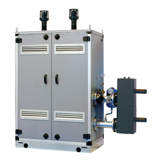
MURELLE EQUIPE
140 BOX ErP
USER, INSTALLATION AND SERVICING INSTRUCTIONS
USER, INSTALLATION AND SERVICING INSTRUCTIONS
ENSURE THAT THESE
INSTRUCTIONS ARE LEFT
FOR THE USER AFTER
COMPLETION OF THE
BENCHMARK SECTION
PLEASE READ THE
IMPORTANT NOTICE
WITHIN THIS GUIDE
REGARDING YOUR BOILER
WARRANTY
199839
ORIGINAL INSTRUCTIONS
Advertisement

Related Manuals for Sime 8111235


Summary of Contents for Sime 8111235
- Page 1 Cod. 6331840A - 08/2021 -R0 MURELLE EQUIPE 140 BOX ErP USER, INSTALLATION AND SERVICING INSTRUCTIONS USER, INSTALLATION AND SERVICING INSTRUCTIONS ENSURE THAT THESE INSTRUCTIONS ARE LEFT FOR THE USER AFTER COMPLETION OF THE BENCHMARK SECTION PLEASE READ THE IMPORTANT NOTICE WITHIN THIS GUIDE REGARDING YOUR BOILER WARRANTY...
- Page 2 SAFE HANDLING This boiler may require 2 or more operatives to move it into its installation site, remove it from its packaging and during movement into its installation location. Manoeuvring the boiler may include the use of a sack truck and involve lifting pushing and pulling.
-
Page 3: Table Of Contents
CONTENTS DEVICE DESCRIPTION ..............pag. INSTALLATION . -
Page 4: Device Description
NOTE: The installation must incorporate a hydraulic separator or plate heat exchanger. The hydraulic separator available from Sime Ltd is supplied with modules in a kit code 8101550 and the tubes connecting the hydraulic separator in the kit code 8101534. It can be assembled on the left-hand side by moving the system supply/return manifold blind flanges. - Page 5 TECHNICAL SPECIFICATIONS MURELLE EQUIPE 140 BOX ErP Generators with a heat output kW 63.2 n° Heat output Nominal (80-60°C) (Pn max) 126.5 Nominal (50-30°C) (Pn max) 136.2 Minimum (80-60°C) (Pn min) 13.4 Minimum (50-30°C) (Pn min) 15.0 Heat input (*) Nominal (Qn max - Qnw max) 130.0 Minimum (Qn min - Qnw min) 14.0...
- Page 6 OPERATING DIAGRAM (fig. 2) 19 20 1 Cascade delivery supply probe (SMC) 15 Pressure transducer 2 Hydraulic compensator 16 Single module drain 3 Antifreeze siphon sensor (SB/SA) 17 Non return valve 4 Safety valve 3.5 bar 18 Pump high efficiency 5 Condensation drain siphon 19 3-way isolation/drain valve 6 Gas valve...
- Page 7 MAIN COMPONENTS (fig. 3) Code 8111235 Model MURELLE EQUIPE 140 BOX ErP Serial n. 9999999999 PAR 1 = 60 (G20) / 62 (G31) PAR 2 = 9 1 System return manifold 2 Gas isolation valve 3 System supply manifold 4 Gas valve 5 Fan 6 Safety thermostat 100°C...
- Page 8 TECHNICAL DATA PLATE (fig. 3/a) MODEL TYPE SERIAL NUMBER CODE YEAR OF CONSTRUCTION PIN NUMBER DIRECTIVE OF REFERENCE WATER CONTENT IN BOILER HEAT INPUT MAX HEAT INPUT MIN HEAT OUTPUT MAX (80-60°C) HEAT OUTPUT MIN (80-60°C) HEAT OUTPUT MAX (50-30°C) HEAT OUTPUT MIN (50-30°C) MAX OPERATING PRESSURE MAX OPERATING PRESSURE...
-
Page 9: Installation
INSTALLATION The unit is suitable for external installation – Hydraulic separator kit code 8101550. respect of other appliances installed in the in a fixed location. – Polypropylene exhaust manifold kit for same area, and seasonal use. Take care It must be installed by qualified engineers indoor installation (purposely treated to that the position of low level vents would in compliance with all instructions con-... - Page 10 2.3.1 Condensation drain connection EXHAUST FOR OUTDOOR INSTALLATION (fig. 5) accordance with BS 7593. Sime Ltd recom- mend only the use of Fernox products for The condensate drain must be connected the flushing and final treatment of the sys- to the civil drain by a pipe with minimum 5 The exhaust terminal for single module Fig.
- Page 11 TUBES CONNECTING THE code 8089530 is required for this type The indicated solutions have the exhaust HYDRAULIC SEPARATOR KIT of installation. For separately supplied manifold positioned both on the modules. accessory assembly see fig. 5. It is however possible to move the exhaust (fig.
- Page 12 6291965 – System return flanged section code 6291965 – Gaskets, nuts and fastening screws M16 – Expansion vessel 8 liters code 6245108 (Preload pressure 1.5 bar – Maximum pressure 10 bar) and connection pipe code 6227661. WARNING: In models “140 BOX ErP” the tubes connecting hydraulic separator kit can be inserted in a specific protective box code 8101517 supplied separately...
- Page 13 HYDRAULIC SEPARATOR The hydraulic separator (available from is supplied separately in a kit Sime Ltd) code 8101550 complete with gaskets, nuts and fastening screws (figure 9). It is mandatory to include a hydraulic sepa- rator in the assembly of the 140 BOX ErP.
- Page 14 2.11 ELECTRICAL NOTE: Sime declines all responsibility dimensions. 230V – 50 Hz single phase CONNECTIONS for injury or damage to persons, animals voltage is required using a fuse protected main switch with at least 3 mm. between or property resulting from the failure to Each module is supplied with a power cord contacts.
- Page 15 2.11.2 Electrical connection of generators in sequence/cascade (fig. 11/a) Line Neutral External sensor Cascade supply probe RS-485 Cascade management board The RS-485 board for management in sequence/cascade is placed at the rear of the control panel of each individual generator as shown in the figure. POLA CN10 CONFIGURATION OF CASCADE PARAMETERS...
- Page 16 607301 (clean electrical contact). 2.11.4 Remote control SIME HOME connection (optional) The heating demand can be controlled by use of remote control unit SIME HOME (code 8092280/81) The remote control unit allows for com- plete control, except lockout reset. The generator will display CR.
-
Page 17: Characteristics
(access to INST and OEM parameters) OFF = Electricity supply to boiler is on but nor ready To be used only with the SIME programming kit and for functioning. However, the protection only by authorised personnel. Do not connect other functions are active. - Page 18 ACCESS TO INSTALLER’S INFORMATION For access to information for the installer, press the key (3 fig. 12). Every time the key is pressed, the display moves to the next item of information. If the key is not pressed, the system automatically quits the function. If there is no expansion board (MIXED ZONE or SOLAR) the relative info will not be displayed.
- Page 19 18. Display of Heating return sensor value (SR) Display of valve closing opening control with board 18. Visualizzazione valore sonda ritorno riscaldamento (SR) 29. Visualizzazione comando chiusura valvola con schedino MIXED ZONE 2 (respectively ON and OFF) ZONA MIX 2 (rispettivamente ON e OFF) 30.
- Page 20 The standard visualisation returns auto- of voltage 1 = Enabled matically after 60 seconds, or by pressing Allocation of SIME HOME channels 0 = Not assigned 1 = Circuit 1 one of the control keys (2 fig. 12). 2 = Three-zone circuit...
- Page 21 BOILER PAR 2 PARAMETERS INSTALLER Instantaneous with diverter valve and flowmeter EXPANSION CARD Instantaneous with diverter valve PAR DESCRIPTION RANGE UNIT OF INC/DEC DEFAULT flowmeter and solar combination MEASUREMENT UNIT SETTING Remote control DHW cylinder Number of expansion boards 0 ... 3 with diverter valve and cylinder Mix valve stroke time 0 ...
- Page 22 – Lack of gas – Interface with the following electronic 8.313 The ignition electrode persists in dis- systems: remote control SIME HOME 5.828 code 8092280/81, thermal regulator charging for max. 10 seconds. If after RVS, connected to a management card 4.161...
- Page 23 HEAD AVAILABLE graph in fig. 14. The speed of the modulat- TO SYSTEM (fig. 14) ing pump system is set as default (installa- tion parameter PAR 13 = Au). Residual head for the heating system is shown as a function of rate of flow in the WILO PARA 25\9-87 1000 1200...
-
Page 24: Commissionimg, Use And Maintenance
“Chimney Sweep “mode as working gas supply pressure. requirements of table 1.3. described in section 4.5.1 and If required contact Sime Ltd for Ensure that this inlet pressure record the measurements from further assistance. can be obtained with all other... - Page 25 GAS CONVERSION (fig. 17) enter when the type of gas fuel is changed. 2) Press the button for a few seconds This operation must be performed by authorised personnel using original Sime MODEL PAR 1 3) Identify the CO values at max. power by components.
- Page 26 MAINTENANCE (fig. 20) To ensure correct operation and efficiency it is important that the boiler is serviced at regular intervals, at least once a year (this may also be a condition of the warranty). Servicing must only be done by a qualified technician.
- Page 27 FUNCTIONING ERRORS Apre When there is a functioning error, an alarm Circuito Circuito riscaldamento 2 appears on the display and the blue lumi- riscaldamento 2 nous bar becomes red. Descriptions of the errors with relative alarms and solutions are given below: Circuito riscaldamento 2 –...
- Page 28 Apre – SAFETY/LIMIT THERMOSTAT ERROR ALARM 07 (fig. 23/6) If either the 95 degree stat or the heat Circuito exchanger safety stat opens, the burner riscaldamento 2 will turn off and ALL 07 will be displayed. Press the key of the controls (2) to start up the boiler again.
- Page 29 (impianto tre zone) – “ALL 15” FAN ERROR (fig. 23/12) – SAFETY THERMOSTAT INTERVENTION – AUXILIARY SENSOR ANOMALY (S3) rcuito scaldamento 2 Circuito SECOND MIXED ZONE “ALL 22” (fig. “ALL 26” (fig. 23/20) The fan speed does not fall within the riscaldamento 2 23/16) rated speed range.
- Page 30 Apre cade connection, error codes 70 and 71 The boiler restarts when the boiler three-zone system configuration is acti- will appear on the SIME HOME remote control display: vated. - ALARM 70 When an anomaly affects cascade oper- ation (cascade delivery sensor ALL 31),...
- Page 31 CIRCULATOR OPERATION FAULTS When an operating anomaly occurs, a co- lored and flashing LED appears on the circulator display. The circulator stops (depending on the type of anomaly) and makes cyclical attempts to restart. Below are the descriptions of the anomalies with relative alarm and solution: ANOMALY CAUSE...
- Page 33 SERVICE RECORD It is recommended that your heating system is serviced regularly and that the appropriate Service Interval Record is completed. Service Provider Before completing the appropriate Service Record below, please ensure you have carried out the service as described in the manufacturer’s instructions. Always use the manufacturer’s specified spare part when replacing controls.
-
Page 36: Fault Finding
FAULT FINDING If an electrical fault occurs on the appli- reads 0 then there is a short circuit. scale. ance the preliminary electrical system Meter set on ø (ohm) x 100 scale. Repeat All switches including thermostat on test checks must be carried out first. it with leads from L to E. - Page 37 APPENDIX 1 Manufacturers Instructions Manufacturer’s instructions must be followed for the correct connection of the condensate discharge pipe from the boiler as this may vary due to the design of the boiler. For example a visible air break and trap is not required if there is a trap with a minimum condensate seal of 75 mm incorporated into the boiler.
- Page 38 Figure 1 – Connection of condensate discharge pipe to internal soil and vent stack. Note – Check manufacturer’s instructions to see if an air break is required. Boiler Visible air break 75 mm trap Visible air break and trap not required if there is a trap with a minimum condensate seal of 75 mm incorporated into the boiler Soil and vent stack Invert...
- Page 39 Internal Condensate Pipe Discharge Termination Figure 2(a) – Connection of a condensate discharge pipe downstream of a sink, basin, bath or shower waste trap. Note – Check manufacturer’s instructions to see if an air break is required. Boiler Visible air break 75 mm trap Visible air break and trap not required if there is a trap with a minimum condensate seal of 75 mm incorporated into the boiler.
- Page 40 Internal Condensate Pipe Discharge Termination Figure 2(b) – Connection of a condensate discharge pipe upstream of a sink, basin, bath or shower waste trap Boiler Visible air break at plug hole – alternative connection can be below sink trap 75 mm sink, basin, bath or shower waste trap Sink, basin, bath or shower with integral overflow Open end of condensate discharge pipe direct into gully 25 mm min below grating but above water level;...
- Page 41 Internal Condensate Pipe Discharge Termination Figure 3 – Connection of a condensate pump - typical method (NB manufacturer’s detailed instructions should be followed). Note – Any external pipe work should be insulated, pipe cut at 45 degrees and a drain/ leaf guard fitted.
- Page 42 Internal Condensate Pipe Discharge Termination Figure 3 – Connection of a condensate pump - typical method (NB manufacturer’s detailed instructions should be followed). Note – Any external pipe work should be insulated, pipe cut at 45 degrees and a drain/ leaf guard fitted.
- Page 43 External Connections External Connections External Connections Only fit an external boiler condensate drain connection if an internal gravity or pumped connection is impractical to install. The pipe work from the boiler should be of a minimum 19mm ID or as per manufacturer’s instructions and the condensate discharge pipe shall be run in a standard drainpipe material, e.g.
- Page 44 External Connections Figure 4 – Connection of condensate discharge pipe to external soil and vent stack Boiler Visible air break 75 mm trap Visible air break and trap not required if there is a trap with a minimum condensate seal of 75mm incorporated into the boiler.
- Page 45 External Connections Alternative Solutions Cold weather protection methods approved or endorsed by boiler manufacturers and/or service organisations may be adopted if these are considered suitable by the parties involved. It is the responsibility of the manufacturer of these products to ensure they have completed the necessary testing or calculations to ensure the product offers suitable protection to prevent the condensate pipe from freezing.
- Page 46 External Connections Electric Trace Heating Trace heating with an external thermostat can be fitted to the external condensate pipe to raise the temperature of the condensate pipe in freezing conditions. Trace heating takes the form of an electrical heating element run in physical contact along the length of the condensate pipe.
- Page 47 External Connections Figure 5 – External termination to rainwater downpipe (NB only combined foul/rainwater drain) Condensate discharge pipe from boiler Pipe size transition point Water/weather proof insulation 43mm 90° male/female bend External rain water pipe into foul water External air break Air gap 68mm PVCu strap on fitting Minimum internal diameter 19mm...
- Page 48 External Connections External Termination of the Condensate Pipe Where the condensate discharge pipe is terminated over an open foul drain or gully, the pipe should terminate below the grating level, but above water level, in order to minimise “wind chill” at the open end. Pipe drainage and resistance to freezing will be improved if the termination end of the condensate pipe is cut at 45 degrees as opposed to a straight cut.
- Page 49 External Connections Figure 6 – External drain, gully or rainwater hopper Boiler Visible air break 38mm minimum trap Visible air break and trap not required if there is a trap with a minimum condensate seal of 38 mm incorporated into the boiler – refer to manufacturers instructions External length of pipe 3 m maximum Open end of condensate discharge pipe direct into gully 25 mm min below grating but above water level;...
- Page 50 External Connections Figure 7 – Example of a purpose made soakaway Condensate discharge pipe from boiler Ground (this section of the condensate discharge pipe may be run either above or below round level); End cut at 45° Diameter 100 mm minimum plastic tube Bottom of tube sealed Limestone chippings Two rows of three 12 mm holes at 25 mm centres, 50 mm from bottom of tube and facing...
-
Page 51: User Instructions
USER INSTRUCTIONS Apre SINGLE MODULE IGNITION (fig. 24) The first ignition of the boiler must be carried out by qualified technical person- nel. Successively, if it is necessary to start up the boiler again, adhere strictly to the following instructions: open the gas tap Circuito to allow the flow of the fuel and move the riscaldamento 2... - Page 52 – ALL 70 and ALL 71 and, if low temperatures are expected, to If the anomaly persists, request assi- These alarms appear on the SIME stance from qualified technical per- HOME remote control display. Re- completely empty the hydraulic circuits sonnel.
-
Page 53: Product Details
PRODUCT DETAILS Murelle Equipe 140 BOX ErP Murelle 70 BOX ErP Classe efficienza energetica stagionale riscaldamento Clase de eficiencia energética estacional en calefacción Classe de eficiência energética do aquecimento ambiente sazonal C.H. energy efficiency class Potenza termica (kW) Potencia térmica (kW) Potência calorífica (kW) Heat output (kW) Consumo annuo di energia riscaldamento (GJ) - Page 54 Daily fuel consumption Recapiti / Datos de contacto Fonderie Sime S.p.A. Via Garbo 27, 37045 Legnago (VR) ITALIA Elementos de contacto / Contact details a. Regime ad alta temperatura: temperatura di ritorno di 60°C all’entrata e 80°C di temperatura di fruizione all’uscita dell’apparecchio b.
- Page 55 NOTES...
- Page 56 Sime Ltd 1a Blue Ridge Park Thunderhead Ridge Glasshoughton, Castleford, WF10 4UA Phone: 0345 901 1114 Fax: 0345 901 1115 www.sime.co.uk Email: enquiries@sime.co.uk...
Need help?
Do you have a question about the 8111235 and is the answer not in the manual?
Questions and answers