Advertisement
Quick Links
EN
EN
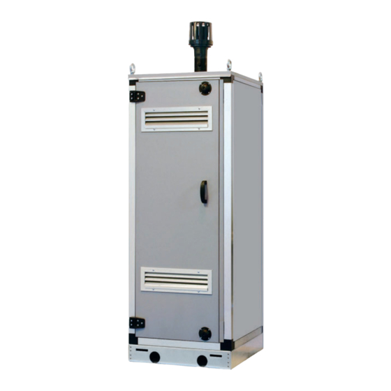
MURELLE 110 BOX ErP
USER, INSTALLATION AND SERVICING INSTRUCTIONS
INSTALLATION AND SERVICING INSTRUCTIONS
INSTALLATION AND SERVICING INSTRUCTIONS
BRAVA DGT HE
BRAVA DGT HE
25 - 30 - 35
25 - 30 - 35
TRANSLATION OF THE ORIGINAL INSTRUCTIONS
Cod. 6316191 - 08/2013
6332393
- 05/2022 - R0
Cod. 6316191 - 08/2013
ENSURE THAT THESE
ENSURE THAT THESE
INSTRUCTIONS ARE LEFT
INSTRUCTIONS ARE LEFT
FOR THE USER AFTER
FOR THE USER AFTER
COMPLETION OF THE
COMPLETION OF THE
BENCHMARK SECTION
BENCHMARK SECTION
PLEASE READ THE
PLEASE READ THE
IMPORTANT NOTICE
IMPORTANT NOTICE
WITHIN THIS GUIDE
WITHIN THIS GUIDE
REGARDING YOUR BOILER
REGARDING YOUR BOILER
WARRANTY
WARRANTY
199839
199838
199838
BOILER DETAILS
please place a sticker
from the installation pack here
Advertisement

Related Manuals for Sime MURELLE 110 BOX ErP


Summary of Contents for Sime MURELLE 110 BOX ErP
- Page 1 Cod. 6316191 - 08/2013 BRAVA DGT HE BRAVA DGT HE 25 - 30 - 35 25 - 30 - 35 MURELLE 110 BOX ErP USER, INSTALLATION AND SERVICING INSTRUCTIONS INSTALLATION AND SERVICING INSTRUCTIONS INSTALLATION AND SERVICING INSTRUCTIONS ENSURE THAT THESE...
- Page 2 For the first year all of our appliances are protected by our manufacturer’s guarantee which covers both parts and labour. As you would expect from Sime Ltd, it is our aim to provide our valued customers with the best in after sales and service.
-
Page 3: Table Of Contents
YOU CAN CHECK YOUR INSTALLER IS GAS SAFE REGISTERED BY CALLING ON 0800 408 5500 OR ALTERNATIVELY WWW.GASSAFEREGISTER.CO.UK COMPLIANCE Our company declares that the MURELLE 110 BOX ErP boilers conform to the essential requirements of the following directives: - Boiler Efficiency Directive 92/42/EEC - Gas Appliances Regulations 2016/426/EC... -
Page 4: Description Of The Appliance
NOTE: The appliance must be turned which are painted, insulated and weather on for the first time by an authorised resistant. MURELLE 110 BOX ErP boilers are pre- technician . They are classed “modules” since they mix/condensing boilers for heating only,... - Page 5 1 .3 SPECIFICATIONS MURELLE 110 BOX ErP Heat output Nominal (80-60°C) (Pn max) 106.2 Nominal (50-30°C) (Pn max) 112.6 Reduced (80-60°C) (Pn min) 20.8 Reduced (50-30°C) (Pn min) 23.2 Heat input (*) Nominal (Qn max - Qnw max) Reduced (Qn min - Qnw min) 21.6 Useful efficiency min/max (80-60°C) 96.4 - 98.3...
- Page 6 The tank (29) must be controlled by an RVS controller (configure the installer parameter PAR 10) . For indoors installations of the MURELLE 110 BOX ErP ONLY,when Murell e HE 92.5 R ErP Murell e HE 110 R ErP hooking up the tank (29): - configure installer parameter PAR 2=6 .
- Page 7 1 .5 MAIN COMPONENTS (fig . 3) Codice/Code 8113360 NOTE: The figure shows Modello/Model MURELLE 110 BOX ErP 1 Control panel the fuel check valve, Matricola/Serial n . 9999999999 2 Electrode on INAIL qualified and cali- 3 Ignition transformer PAR 1 = 68 (G20) / 70 (G31) brated to 98°C, which is 4 Smoke flue gas probe (SF) PAR 2 = 9...
-
Page 8: Installation
WARNING: Failure to wash the heating (fig . 4) circuit or add a suitable inhibitor to it voids MURELLE 110 BOX ErP heating modules the appliance’s warranty . The filling pressure with the system cold must be 1 .5 bar. Fill the system slowly,... - Page 9 2 .7 FLUE GAS MANIFOLD FOR INDOORS INSTALLATIONS (fig . 6) For this type of installation, refer to fig. 6. The indicated solutions use the flue gas manifold (optional, code 8102510) with outlet to the right of the modules. You can move the outlet to the left by simply rotating the manifold through 180°.
- Page 10 2 .8 RS-485 BOARD (fig . 7) 2 .8 .1 MODBUS mode panel and is supplied as an optional kit, code 8092249. The RS-485 enables you to control up to 8 This mode enables communications over a boilers in a series/cascade configuration. MODBUS network of at least two boilers in The board installs to the back of the control a cascade configuration, and requires the...
- Page 11 LOAD LOSSES (fig . 8) request a new one from SIME. connection. The power supply must be single-phase, NOTE: SIME declines all liability for dam- rated 230V - 50Hz, using a main switch The hydraulic separator load losses are LATO CALDAI A...
- Page 12 Zone 1 ambient thermostat Ignition transformer Zone 2 ambient thermostat High-efficiency system pump Siphon antifreeze sensor code 6319158 code 6319144 SIME HOME remote control (optional) code 6319156 Temperature-limit thermostat External temperature sensor (optional) Electrode on Mechanical timer (optional) code 6316203...
-
Page 13: Characteristics
ON/OFF BUTTON PC CONNECTION ON = Boiler has electric power This should only be used with the SIME programming kit OFF = Boiler has electrical power but is not opera- and only by authorised technicians. Do not connect it to tional. - Page 14 3 .2 ACCESS TO INSTALLER INFORMATION To access installer information, press (3 fig. 12). Pressing this button displays the next info item: If you do not press ( ), the system automatically suits the function. If no expansion board is connected (MIX ZONE or SOLAR), the associated info is not displayed. List of info items: 1 .
- Page 15 18 . Heating return temperature sensor (SR) 29 . Valve status with MIXED ZONE board 2 (ON/OFF) 18. Visualizzazione valore sonda ritorno riscaldamento (SR) 29. Visualizzazione comando chiusura valvola con schedino ZONA MIX 2 (rispettivamente ON e OFF) 19 . Cascade delivery temperature (when fitted) 30 .
- Page 16 0 = Disabled 1 = Enabled after 60 seconds or when one of the con- SIME HOME channel assignments 0 = Not assigned trol buttons is pressed (2 fig. 12), except re in h x 100 (es. 14.000 e 10) 1 = Circuit 1 for RESET.
- Page 17 BOILER PAR 2 INSTALLER PARAMETERS Instantaneous with diverter valve and flowmeter EXPANSION BOARD Instantaneous with diverter valve, flowmeter and solar PAR DESCRIPTION RANGE UNIT STEP DEFAULT connection Remote boiler with diverter valve Number of expansion boards 0 ... 3 and DHW sensor ver. T Mix valve motion time 0 ...
- Page 18 After ignition, the electrode continues 3 .7 ELECTRONIC IGNITION – Interface for the following devices: sparking even though the burner has SIME HOME remote control, code ignited. Flame ignition and detection are handled 8092281, RVS temperature regulators, After 10 seconds the electrode stops...
-
Page 19: Use And Maintenance
MIN power This must only be done by an author- METHANE 110 BOX ErP (Methane) (Propane) ised technician using original Sime parts . (G20) 9.0 ±0.2 10.2 ±0.3 Failure to do so voids the warranty . 6) Press the buttons (... - Page 20 Fig. 20 4 .5 .1 Chimney sweep function (fig . 21) To check the boiler’s combustion, hold down the installer button ( ) for a few Fig. 21 seconds. chimney sweep function will run for 15 minutes. The boiler will run at maximum power and WARNING: turn off at 80°C and then back on again at The function can be disabled by pressing...
- Page 21 Apre 4 .6 MALFUNCTIONS Circuito Circuito riscaldamento 2 When a malfunction is detected, the display riscaldamento 2 will show an alarm and the light bar turns red. We describe the potential faults, their alarms and solutions below: – LOW WATER PRESSURE FAULT “ALL 02” Circuito Circuito (fig .
- Page 22 Apre – SAFETY/LIMIT THERMOSTAT FAULT “ALL 07” (fig . 23/6) Circuito Opening the connection to the safety/ riscaldamento 2 limit thermostat turns the boiler off, while the flame detector waits for it to close for a minute, keeping the system on for this time.
- Page 23 Circuito riscaldamento 2 ircuito scaldamento 2 Circuito – FAN FAULT “ALL 15” (fig . 23/12) – SECOND MIXED ZONE SAFETY THER- – AUXILIARY SENSOR (S3) FAULT “ALL riscaldamento 3 (impianto tre MOSTAT TRIPPED “ALL 22” (fig . 23/16) 26” (fig . 23/20). The fan speed is not in the expected zone) ircuito...
- Page 24 3 zone sys- tem is configured properly. Apre WARNING: If connected in sequence/cas- cade, the display of the SIME HOME re- mote control shows fault codes 70 and 71: - ALARM 70 When a malfunction blocks operation of Fig.
- Page 25 GAS BOILER SYSTEM COMMISSIONING CHECKLIST & WARRANTY VALIDATION RECORD Address: Boiler make and model: Boiler serial number: Commissioned by (PRINT NAME): Gas Safe registration number: Company name: Telephone number: Company email: Company address: Commissioning date: Heating and hot water system complies with the appropriate Building Regulations? Time, temperature control and boiler interlock provided for central heating and hot water Boiler Plus requirements (tick the appropriate box(s)) Weather compensation...
- Page 26 SERVICE & INTERIM BOILER WORK RECORD It is recommended that your boiler and heating system are regularly serviced and maintained, in line with manufacturers’ instructions, and that the appropriate service / interim work record is completed. Service provider When completing a service record (as below), please ensure you have carried out the service as described in the manufacturers’ instructions. Always use the SERVICE/INTERIM WORK ON BOILER SERVICE/INTERIM WORK ON BOILER Date:...
-
Page 29: Exploded Views For Spare Parts
EXPLODED VIEWS FOR SPARE PARTS... - Page 31 ATTENTION: use only original spare parts. Failure to comply with the above may compromise the safety of the device and the immediate forfeiture of the warranty. Position Code Description Where used Advised parts 6138555 Right/left hand side frame part 6256731 Main exchanger rear support 6138896 Frame assembly lower side...
- Page 32 6291966 ISPESL safeties pipe 6146004 Thermometer 0-120¢C 6216606 Manometer cock ISPESL 1/4" 6216650 Manometer cock connection pipe 2030225 Gasket Ø 5,5x11x2 6217051 Manometer 0/10 bar 6001409 H.L. stat 100¢C 6291981 Water pressure switch block 6291982 90¢ MM G 1/4" curve 6037551 Min.m.reset water press.switch 6037550...
-
Page 33: Appendix 1 (Hhic Guidelines)
APPENDIX 1 (HHIC GUIDELINES) Manufacturers Instructions Manufacturer’s instructions must be followed for the correct connection of the condensate discharge pipe from the boiler as this may vary due to the design of the boiler. For example a visible air break and trap is not required if there is a trap with a minimum condensate seal of 75 mm incorporated into the boiler. - Page 34 Figure 1 – Connection of condensate discharge pipe to internal soil and vent stack. Note – Check manufacturer’s instructions to see if an air break is required. Boiler Visible air break 75 mm trap Visible air break and trap not required if there is a trap with a minimum condensate seal of 75 mm incorporated into the boiler Soil and vent stack Invert...
- Page 35 Internal Condensate Pipe Discharge Termination Figure 2(a) – Connection of a condensate discharge pipe downstream of a sink, basin, bath or shower waste trap. Note – Check manufacturer’s instructions to see if an air break is required. Boiler Visible air break 75 mm trap Visible air break and trap not required if there is a trap with a minimum condensate seal of 75 mm incorporated into the boiler.
- Page 36 Internal Condensate Pipe Discharge Termination Figure 2(b) – Connection of a condensate discharge pipe upstream of a sink, basin, bath or shower waste trap Boiler Visible air break at plug hole – alternative connection can be below sink trap 75 mm sink, basin, bath or shower waste trap Open end of condensate discharge pipe direct into gully 25 mm min below grating but above water level;...
- Page 37 Internal Condensate Pipe Discharge Termination The possibility of waste pipes freezing downstream of the connection point should be considered when determining a suitable connection point - e.g. a slightly longer pipe run to an internal soil stack may be preferable to a shorter run connecting into a kitchen waste pipe discharging directly through the wall to an external drain.
- Page 38 Internal Condensate Pipe Discharge Termination Figure 3 – Connection of a condensate pump - typical method (NB manufacturer’s detailed instructions should be followed). Note – Any external pipe work should be insulated, pipe cut at 45 degrees and a drain/ leaf Condensate discharge from boiler Condensate pump Visible air break at plug hole...
- Page 39 External Connections External Connections pumped connection is impractical to install. The pipe work from the boiler should be of a minimum 19mm ID or as per manufacturer’s instructions and the condensate discharge pipe shall be run in a standard drainpipe material, e.g. poly (vinyl chloride) (PVC), un-plasticized poly (vinyl chloride) (PVC-U), acrylonitrile butadiene-styrene (ABS), polypropylene (PP) or chlorinated poly (vinyl chloride) (PVC-C).
- Page 40 External Connections Figure 4 – Connection of condensate discharge pipe to external soil and vent stack Boiler Visible air break 75 mm trap Visible air break and trap not required if there is a trap with a minimum condensate seal of 75mm incorporated into the boiler.
- Page 41 External Connections Alternative Solutions Cold weather protection methods approved or endorsed by boiler manufacturers and/or service organisations may be adopted if these are considered suitable by the parties involved. It is the responsibility of the manufacturer of these products to ensure they have completed the necessary testing or calculations to ensure the product offers suitable protection to prevent the condensate pipe from freezing.
- Page 42 External Connections Electric Trace Heating condensate pipe to raise the temperature of the condensate pipe in freezing conditions. Trace heating takes the form of an electrical heating element run in physical contact along the length of the condensate pipe. The pipe is usually covered with thermal insulation to retain heat losses from the pipe.
- Page 43 External Connections Figure 5 – External termination to rainwater downpipe (NB only combined foul/rainwater drain) Condensate discharge pipe from boiler Pipe size transition point Water/weather proof insulation 43mm 90° male/female bend External rain water pipe into foul water External air break Air gap Minimum internal diameter 19mm Minimum internal diameter 30mm...
- Page 44 External Connections External Termination of the Condensate Pipe Where the condensate discharge pipe is terminated over an open foul drain or gully, the pipe should terminate below the grating level, but above water level, in order to minimise “wind chill” at the open end. Pipe drainage and resistance to freezing will be improved if the termination end of the condensate pipe is cut at 45 degrees as opposed to a straight cut.
- Page 45 External Connections Figure 6 – External drain, gully or rainwater hopper Boiler Visible air break 38mm minimum trap Visible air break and trap not required if there is a trap with a minimum condensate seal of 38 mm incorporated into the boiler – refer to manufacturers instructions External length of pipe 3 m maximum Open end of condensate discharge pipe direct into gully 25 mm min below grating but above water level;...
- Page 46 External Connections Figure 7 – Example of a purpose made soakaway Condensate discharge pipe from boiler Ground (this section of the condensate discharge pipe may be run either above or below round level); End cut at 45° Diameter 100 mm minimum plastic tube Bottom of tube sealed Limestone chippings Two rows of three 12 mm holes at 25 mm centres, 50 mm from bottom of tube and facing...
-
Page 47: For The User
TURNING ON AND OPERATION Apre TURNING THE MODULE ON (fig . 24) The module must be turned on for the first time by Sime Authorised Technical Circuito Service. If you need to turn the module on riscaldamento 2 thereafter, proceed as follows: open the gas valve to allow gas to flow to the ap- pliance and set the main switch to “ON”. - Page 48 Apre shown in the figure. Set the values with the buttons ( To return to the standard display, press the button ( ) or just leave it alone for Apre 10 seconds. Heating circuit 2 Circuito REGULATION WITH EXTERNAL riscaldamento 2 SENSOR CONNECTED (fig.
- Page 49 – ALL 70 and ALL 71 (impianto tre These alarms display zone) SIME HOME remote control . Contact your local Authorised Technical Ser- vice Centre . GAS TYPE CHANGEOVER Fig. 27/d If you need to have the gas type changed, contact exclusively your local SIME Authorised Technical Service Centre.
-
Page 50: Appendix
APPENDIX PRODUCT DATA SHEET Murelle 110 BOX ErP Classe efficienza energetica stagionale riscaldamento Clase de eficiencia energética estacional en calefacción Classe de eficiência energética do aquecimento ambiente sazonal C.H. energy efficiency class Potenza termica (kW) Potencia térmica (kW) Potência calorífica (kW) Heat output (kW) Consumo annuo di energia riscaldamento (GJ) Consumo anual de energía en calefacción (GJ) - Page 51 ANNEX AA .1 - MURELLE 110 BOX ErP (code 8113360) Informazioni da fornire per le caldaie per il riscaldamento d’ambiente e le caldaie miste Información obligatoria para calderas de calefacción de espacios y calderas mixtas Informações a fornecer para aquecedores de ambiente com caldeira e aquecedores combinados com caldeira...
- Page 52 Sime Ltd 1a Blue Ridge Park Thunderhead Ridge Glasshoughton, Castleford, WF10 4UA Phone: 0345 901 1114 Fax: 0345 901 1115 www.sime.co.uk Email: enquiries@sime.co.uk...
Need help?
Do you have a question about the MURELLE 110 BOX ErP and is the answer not in the manual?
Questions and answers