Sime MURELLE EQUIPE 100 BOX ErP Manual
Hide thumbs
Also See for MURELLE EQUIPE 100 BOX ErP:
- Original instructions manual (73 pages) ,
- Manual (72 pages) ,
- User, installation and servicing instructions (56 pages)

Related Manuals for Sime MURELLE EQUIPE 100 BOX ErP


Summary of Contents for Sime MURELLE EQUIPE 100 BOX ErP
- Page 1 MURELLE EQUIPE 100-150 BOX ErP Fonderie SIME S.p.A Cod. 6322833B - 01/2018 INSTRUCCIONES ORIGINALES-ORIGINAL INSTRUCTIONS...
- Page 2 FOR THE INSTALLATION TECHNICIAN CONTENTS DEVICE DESCRIPTION ........................page..36 INSTALLATION.............................page..41 FEATURES............................page..50 USE AND MAINTENANCE ........................page..57 CONFORMITY Our. Company. declares. that. MURELLE.EQUIPE. 100-150. ErP. boilers. comply. with. the. essential. require- ments.of.the.following.directives: -.Boiler.Efficiency.Directive.92/42/EEC -.Gas.Appliances.Directive.2009/142/EC.up.to.20/04/18.and.Gas.Regulation.2016/426/EC.from.21/04/18 -.Electromagnetic.Compatibility.Directive.2014/30/UE -.Low.Voltage.Directive.2014/35/UE -.Ecodesign.Directive.2009/125/EC -.Regulation.(EU).N..813/2013.-.811/2013 IMPORTANT When.turning.the.boiler.on.for.the.first.time.it.is.best.to.run.the.following.checks: –.
-
Page 3: Device Description
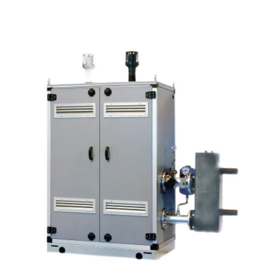
DEVICE DESCRIPTION INTRODUCTION pre-mixed. condensation. heating. modu- to.work.singularly.or.in.sequence/casca- les.intended.only.for.heating,.inter-con- de.autonomously. MURELE EQUIPE 100-150 BOX ErP. are. nectible.and.easy.to.assemble,.designed. DIMENSIONS MODULES 1.2.1 “MURELLE EQUIPE 100 BOX ErP” MURELLE EQUIPE 100 BOX ErP 1775 1100 FIXTURES M.. System.supply.G.2”.(UNI.-.ISO.7/1) R.. System.return.G.2”.(UNI.-.ISO.7/1) G.. Gas.(Flange.PN6-DN50). S3. Condensation.drain.ø.40 NOTE: Assembly of a hydraulic separator or plate exchanger is also mandatory. - Page 4 1.2.2 “MURELLE EQUIPE 150 BOX ErP” MURELLE EQUIPE 150 BOX ErP 1100 (Murelle Equipe 100 BOX ErP) 1730 FIXTURES M.. System.supply.G.2”.(UNI.-.ISO.7/1) R.. System.return.G.2”.(UNI.-.ISO.7/1) G.. Gas.(Flange.PN6-DN50). S3. Condensation.drain.ø.40 NOTE: Assembly of a hydraulic separator or plate exchanger is also mandatory. The hydraulic separator is supplied with modules in a kit code 8101550 and the tubes connecting the hydraulic separator in the kit code 8101534.
- Page 5 TECHNICAL SPECIFICATIONS MURELLE EQUIPE 100 BOX ErP 150 BOX ErP Generators with a heat output kW 46.7. n°. Heat output Nominal.(80-60°C).(Pn.max). 93.4. 140.1 Nominal.(50-30°C).(Pn.max). 102.0. 153.0 Minimum.(80-60°C).(Pn.min). 9.2. Minimum.(50-30°C).(Pn.min). 10.5. 10.5 Heat input (*) Nominal.(Qn.max.-.Qnw.max). 96.0. 144.0 Minimum.(Qn.min.-.Qnw.min). 9.6. Min/max operating yield (80-60°C). 96.1/97.3.
- Page 6 OPERATING DIAGRAM 19 20 1. Cascade.supply.probe.(SMC) 2. Hydraulic.compensator 3. ---------- . 5. Condensation.drain.siphon . 6. Gas.valve . 7. ---------- . 8. Fan . 9. Heating.supply.probe.(SM) .10. Safety.thermostat.100°C .11. Sensor.fumes.(SF) .12. Primary.exchanger .14. Heating.return.probe.(SR) .15. Pressure.transducer .17. Check.valve .18. Pump.high.efficiency 19.. ---------- 20..
- Page 7 MAIN COMPONENTS Codice/Code 8111227 Modello/Model MURELLE EQUIPE 100 BOX ErP Matricola/Serial n. 9999999999 PAR 1 = 5 (G20) / 13 (G31) PAR 2 = 9 . 1. System.return.manifold . 2. Gas.tap . 3. System.supply.manifold . 4. Gas.valve . 5. Fan .
-
Page 8: Installation
INSTALLATION Installation.is.permanent.and.must.exclusi- –. Polypropylene. exhaust. manifold. kit. for. the.outer.walls.for.room.ventilation.. vely.be.performed.by.specialised.and.quali- indoor. installation. (purposely. treated. to. fied.personnel,.following.all.the.instructions. resist. weathering. when. installed. outdo- and. provisions. included. in. this. manual.. ors): 2.2.2 Outdoors . code.8102511.for.“100 BOX ErP” module Current.regulations.must.also.be.met. . code.8102512.for.“150 BOX ErP” module MURELLE EQUIPE 100-150 BOX ErP heat. - Page 9 Sentinel X100 or Fernox Protector F1. is. the.meter.and.any.utility.device.no.greater. gas.main.pipes.. recommended. after. cleaning. the. system.. than.1.0.mbar.for.second.family.gas.(natu- To. prevent. malfunctioning. of. the. valve,. or. It. is. important. to. check. the. concentration. ral.gas)..A.sticker.inside.the.module.inclu- in. certain. cases. even. to. cut. out. the. safety. of.the.inhibitor.after.each.system.modifica- des.identification.and.gas.type.data.specific.
- Page 10 INDOOR INSTALLATION The. indicated. solutions. have. the. exhaust. 180°. NOTE: The kits are purposely treated also EXHAUST KIT (fig. 6) manifold. positioned. both. on. the. modules.. It.is.however.possible.to.move.the.exhaust. to resist weathering when installed outdo- Refer.to.fig..6.for.this.type.of.installation.. of. the. left. by. simply. rotating. the. manifold. ors.
- Page 11 TUBES CONNECTING THE HYDRAULIC SEPARATOR KIT (fig. 7) SIME. provides. the. tubes. connecting. the. hydraulic.separator.kit.code.8101534.for.in- stallations.with.left-hand.side.attachments. The.kit.is.made.up.of.the.following.compo- nents.(fig..7): –..System. supply. flanged. section. code. 6291965 –..System. return. flanged. section. code. 6291965 –..Gaskets,.nuts.and.fastening.screws.M16 –..Expansion. vessel. 8. liters. code. 6245108. (Preload. pressure. 1.5. bar. –. Maximum.
- Page 12 CONNETTORE CABLATO (cod. 6319173) WIRED CONNECTOR (cod 6319173) DIP SWITCH DIP SWITCH GESTIONE IN MODBUS GESTIONE IN CASCATA MODBUS MANAGEMENT CASCADE MANAGEMENT 1 2 3 COMUNICAZIONE MODBUS MODBUS COMMUNICATION TABELLA PAR 17 INST/ Tab. PAR 17 INST INSTALLER PARAMETER SETTING: PAR 17 INST Baud Rate N°...
- Page 13 TABELLA DELLE VARIABILI MODBUS / MODBUS BOILER VARIABLES LIST Descrizione / Function Variable description Digital variables (COILS) Boiler CH Enable/Request D R/W Richiesta riscaldamento zona 1 Request CH zone 1 Abilitazione preparazione ACS Enable DHW preparation Boiler DHW Enable D R/W Boiler Water Filling Function D R/W Non usato...
- Page 14 2.10 HYDRAULIC SEPARATOR The. hydraulic. separator. is. supplied. sepa- rately. in. a. kit. code. 8101550. complete. with. gaskets,.nuts.and.fastening.screws.(figure. 9).. The.compensator.is.required.in.the.assem- bly.of.modules.100-150 BOX ErP. WARNING: The hydraulic separator can be inserted in a specific protective box code 8101517 supplied separately. 2.10.1 Load loss hydraulic separator (fig.
- Page 15 ELECTRICAL ordered.from.SIME. connection. CONNECTIONS 230V.–.50.Hz.single.phase.voltage.is.requi- red. using. a. fuse. protected. main. switch. NOTE: SIME shall not be liable for any Each.module.is.supplied.with.a.power.cord. with. at. least. 3. mm.. between. contacts.. damages to persons and things due to lack of boiler grounding. which,.if.replacement.is.required,.must.be.
- Page 16 2.11.2 Electrical connection of modules in sequence/cascade (fig. 11/a) Line Neutral External.sensor SMC. Cascade.supply.probe RS-485. Cascade.management.board NOTICE: The external temperature probe (SE) must be connected to the MASTER boiler and the cascade supply probe (SMC) to the SLAVE 1 boiler. The SE, SMC probes and the RS-485 board connection cable are supplied together with the modules in the probe kit code 8092250.
-
Page 17: Features
3 - KEYS RESERVED FOR THE INSTALLER ON/OFF KEYS (access to INST and OEM parameters) ON.=.. Electricity.supply.to.boiler.is.on PC CONNECTION OFF.=.. Electricity. supply. to. boiler. is. on. but. nor. To.be.used.only.with.the.SIME.programming.kit.and.only. ready. for. functioning.. However,. the. protec- by.authorised.personnel..Do.not.connect.other.electro- tion.functions.are.active. nic.devices.(cameras,.telephones,.mp3.players,.etc.).Use. SUMMER MODE KEY a.tool.to.remove.the.cap.and.reinsert.after.use. - Page 18 ACCESS TO INSTALLER’S INFORMATION For.access.to.information.for.the.installer,.press.the.key. .(3.fig...14)..Every.time.the.key.is.pressed,.the.display.moves.to.the.next. item.of.information..If.the.key. .is.not.pressed,.the.system.automatically.quits.the.function..If.there.is.no.expansion.board.(ZONA.MIX. or.INSOL).the.relative.info.shall.not.be.displayed..List.of.information: 1.. Visualisation. of. external. temperature,. 9.. Visualisation.fan.speed.in.rpm.x.100.(e.g..4.800.and.1850.rpm) 1...Visualizzazione.temperatura.esterna 9...Visualizzazione.numero.giri.ventilatore.in.rpm.x.100.(es..4.800.e.1.850.rpm) only.with.external.sensor.connected ..solo.con.sonda.esterna.collegata 2...Visualizzazione.temperatura.sonda 2.. Visualisation.of.C.H..flow.sensor.(SM) 10..Visualisation.of.hours.of.functioning.of.the.burner.in.h.x.100.(e.g..14000.and.10) 10...Visualizzazione.ore.di.funzionamento.del.bruciatore.in.h.x.100.(es..14.000.e.10) ..mandata.riscaldamento.(SM) 3.. Visualisation. of. D.H.W.. temperature. sen- 3..Visualizzazione.temperatura.sonda 11...Visualisation.of.number.of.times.the.burner.has.ignited.x.1000.(e.g..97000.and.500) 11...Visualizzazione.numero.di.accensioni.del.bruciatore.x.1.000.(es..97.000.e.500) ..sanitario.(SS).solo.per.caldaie.istantanee sor.(SS).only.for.instantaneous.boilers 4.. Visualisation. of. auxiliary. temperature. 12..
- Page 19 18..Visualisation.C.H..return.sensor.value.(SR) 29.. Visualisation.valve.closing.opening.control.with.board.ZONA.MIX. 18. .Visualizzazione.valore.sonda.ritorno.riscaldamento.(SR) 29. .Visualizzazione.comando.chiusura.valvola.con.schedino ..ZONA.MIX.2.(rispettivamente.ON.e.OFF) 2..(respectively.ON.and.OFF) 30..Visualisation. solar. probe. temperature. value. S1. with. 19..Visualisation.collector.probe.value 30. .Visualizzazione.valore.temperatura.sonda.solare.S1 19. .Visualizzazione.valore.sonda.collettore.cascata ..con.schedino.solare.INSOL solar.board.INSOL 31..Visualisation. solar. probe. temperature. value. S2. with. 20..Visualisation. delivery. probe. value. mixed. with. board. 31...Visualizzazione.valore.temperatura.sonda.solare.S2 20. .Visualizzazione.valore.sonda.mandata.impianto.miscelato ..con.schedino.solare.INSOL solar.board.INSOL ..con.schedino.ZONA.MIX.1.(ingresso.S2)
- Page 20 5.=.Heat.pump the. default. parameters. can. be. changed. 6.=.Zone.2.valve. with.the.keys. . and. Luminous.bar.indicating.presence. 0.=.Disabled. The.standard.visualisation.returns.automa- of.voltage. 1.=.Enabled tically.after.60.seconds,.or.by.pressing.one. Allocation.of.SIME.HOME.channels... 0.=.Not.assigned. 1.=.Circuit.1. of. the. control. keys. (2. fig.. 12). excluded. the. es..14.000.e.10) 2.=.Three-zone.circuit key.RESET. Fan.rpm.Step.ignition. 0,0..81. rpmx100.0,1 from.0,1.to.19,9. 0,0 1 from.20.to.81 Long.chimneys.
- Page 21 BOILER PAR 2 PARAMETERS INSTALLER Instant.with.deviator.valve.. and.flowmeter EXPANSION CARD Instant.with.deviator.valve,.. .flowmeter.and.solar.combination PAR.DESCRIPTION... RANGE. UNIT.OF. INC/DEC.. DEFAULT MEASUREMENT. UNIT. SETTING D.H.W..tank.with. Number.of.expansion.boards.. 0..3. .deviator.valve.and.boiler.sensor.. Mix.valve.stroke.time. 0..199. 10.sec.. vers..T.(LOW.INERTIA). Priority.of.D.H.W..over.mixed.zone. 0.=.Paralle. 1.=.Absolute On.board.D.H.W..tank.with Floor.drying. 0.=.No.activated. .deviator.valve.and.D.H.W..sensor... 1.=.Curve.A (LOW.INERTIA). 2.=.Curve.B . R emote.D.H.W..tank.with.deviator. 3.=.Curve.A+B .
- Page 22 12.090 maximum.flexibility.in.use.of.the.system. pipes 8.313 –. Interface. with. the. following. electronic. It.can.be.caused.by.a.closed.gas.tap.or.by. 5.828 systems:. remote. control. SIME.HOME. a.broken.valve.coil.(the.interruption.does. 4.161 code. 8092280/81,. thermal. regulator. not.allow.for.opening).. 3.021 RVS,. connected. to. a. management. card. 2.229 of.a.mixed.zone.ZONA.MIX.code.8092234,.
- Page 23 Portata POMPA POMPA MODULANTE A FISSA VELOCITA’ VARIABILE (M) (l/h) (mbar) (mbar) 1000 1200 1400 electronic.board.is.faulty. HEAD AVAILABLE The.speed.of.the.modulating.pump.system. 1600 TO SYSTEM (fig. 14) is. set. as. default. (installation. parameter. . 1800 In.the.case.of.a.sudden.lack.of.voltage,.the. PAR 13 = Au).. 2000 burner. will. immediately. switch. off.. When. Residual.
-
Page 24: Use And Maintenance
Fig..16 Fig..17 latore.in.rpm.x.100.(es..4.800.e.1.850.rpm) necessary.to.set.SET.14,.by.pressing.the.key. 2). Press.the.button.for.a.few.seconds GAS CONVERSION (fig. 17) This operation must be performed by 3). Identify.the.CO .values.at.max..power.by. nto.del.bruciatore.in.h.x.100.(es..14.000.e.10) authorised personnel using original Sime adjusting.the.shutter.(5.fig..16): components. MAX power To.convert.from.natural.gas.to.LPG.or.vice. (Methane) (Propane) versa,.perform.the.following.operations 9,2.±0,2. 10,3.±0,3 The. standard. display. will. automatically. - Page 25 During maintenance operations, it is important to verify that the drip-plate with drain trap contains water (this check is particularly important if the generator has not been used for extended periods of time). If necessary, the drip plate can be filled using the tap provided (fig.
- Page 26 4.5.3 Pump high efficiency diagnose and remedy (fig. 22/a) LED diagnose and remedy Led color Meaning Diagnostic Cause Remedy Continuous green Normal.running Pump.run.as. Normal.operation expected.or.is.faced. to.a.phenomenon. that.shortly.affects. its.running Red/green blinking Abnormal.situation. Pump.will.restart. 1..Undervoltage.or. 1..Check.voltage.supply:. (pump.functional. by.itself.after.the. Overvoltage:. 195V<U<253V but.stopped) abnormal.situation. .
- Page 27 FUNCTIONING ANOMALIES Apre Circuito When. there. is. a. functioning. anomaly,. an. Circuito riscaldamento 2 alarm.appears.on.the.display.and the blue riscaldamento 2 luminous bar becomes red. Descriptions.of.the.anomalies.with.relative. alarms.and.solutions.are.given.below: Circuito riscaldamento 2 –. LOW WATER PRESSURE ANOMALY ALARM 02 (fig. 23/1) Circuito Circuito If.the.pressure.detected.by.the.transdu- riscaldamento 3 riscaldamento 3 (impianto tre...
- Page 28 Apre –. SAFETY/LIMIT THERMOSTAT ANOMALY ALARM 07 (fig. 23/6) If.the.connection.with.the.safety.thermo- Circuito stat/limit. thermostat. is. interrupted,. the. riscaldamento 2 boiler. will. stop;. the. flame. control. will. remain.waiting.to.be.switched.off.for.one. minute,.keeping.the.system.pump.on.for. that.period.. . If,.the.thermostat.connection.is.restored. within.the.minute,.the.boiler.will.start.up. Circuito Circuito working.normally.again,.otherwise.it.will. riscaldamento 3 riscaldamento 2 stop.and.the.display.will.show.the.alarm. (impianto tre Apre ALL.07.
- Page 29 (impianto tre zone) Apre Circuito –. “ALL 15” FAN ERROR (fig. 23/12) –. SAFETY THERMOSTAT INTERVENTION –. AUXILIARY SENSOR ANOMALY (S3) riscaldamento 2 Circuito SECOND MIXED ZONE “ALL 22” (fig. . The.fan.speed.does.not.fall.within.the.ra- riscaldamento 2 “ALL 26” (fig. 23/20) ted.speed.range.. 23/16) When.
- Page 30 ALL. 32. is. di- CAUTION: In the event of sequence/casca- splayed.. de connection, error codes 70 and 71 will . The.boiler.restarts.when.the.boiler.three- appear on the SIME HOME remote control zone.system.configuration.is.activated display: - ALARM 70 When an anomaly affects cascade ope-...
- Page 31 USER INSTRUCTIONS WARNINGS – The appliance can be used by children under 8 years and by persons with reduced physical, sensory or mental capabilities, or lack of experience or knowledge, provided they are un- der supervision or after they have been given instructions concerning the safe handling of the appliance and the understanding of the dangers inherent to it.
- Page 32 Request assistance from qualified tech- zone) zone) nical personnel. Circuito riscaldamento 2 –. ALL 70 and ALL 71 These alarms appear on the SIME HOME remote control display. Request assi- Circuito stance from qualified technical person- riscaldamento 3 Fig..27/d Fig..27/a (impianto tre nel.
- Page 33 GREEN LED PUMP HIGH EFFICIENCY (fig. 28) If. the. LED. signal. is. missing. or. the. colour. changes. (blinking. red/green. or. blinking. red),.contact.an.authorised.technician. Fig..28 GAS CONVERSION If. it. is. necessary. to. change. to. a. different. type. of. gas,. request. assistance. only. from. authorised.technical.personnel.
- Page 34 APPENDIX DETALLES DEL PRODUCTO / PRODUCT DETAILS Murelle Equipe 100 BOX ErP 150 BOX ErP Classe efficienza energetica stagionale riscaldamento Clase de eficiencia energética estacional en calefacción Classe de eficiência energética do aquecimento ambiente sazonal C.H. energy efficiency class Potenza termica (kW) Potencia térmica (kW) Potência calorífica (kW) Heat output (kW)
- Page 35 Daily fuel consumption Recapiti / Datos de contacto Fonderie Sime S.p.A. Via Garbo 27, 37045 Legnago (VR) ITALIA Elementos de contacto / Contact details a. Regime ad alta temperatura: temperatura di ritorno di 60°C all’entrata e 80°C di temperatura di fruizione all’uscita dell’apparecchio b.
- Page 36 Daily fuel consumption Recapiti / Datos de contacto Fonderie Sime S.p.A. Via Garbo 27, 37045 Legnago (VR) ITALIA Elementos de contacto / Contact details a. Regime ad alta temperatura: temperatura di ritorno di 60°C all’entrata e 80°C di temperatura di fruizione all’uscita dell’apparecchio b.
- Page 37 NOTES...
- Page 39 Fonderie.Sime.S.p.A..-..Via.Garbo,.27..-..37045.Legnago.(Vr). Tel..+39.0442.631111..-..Fax.+39.0442.631292..-..www.sime.it...
Need help?
Do you have a question about the MURELLE EQUIPE 100 BOX ErP and is the answer not in the manual?
Questions and answers