Advertisement
Quick Links
Cod. 6332324A - 04/2024 - R0
EN
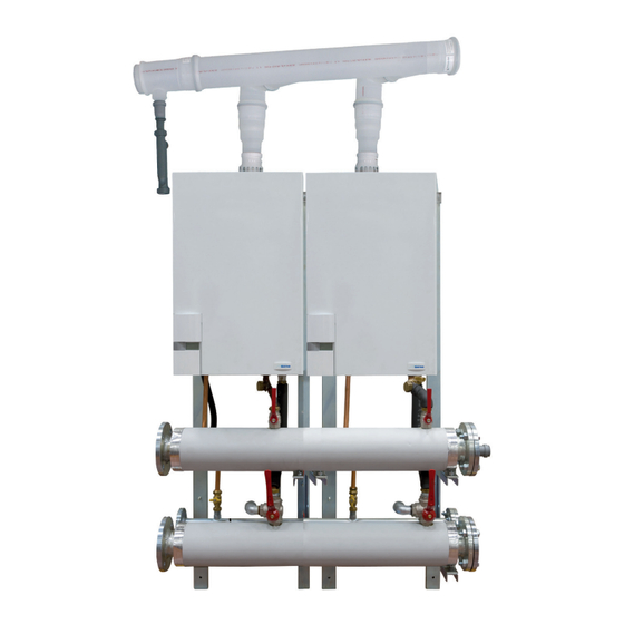
MURELLE EQUIPE 140 ErP
(PACK OF 2 MURELLE HE 70 R ErP)
INSTALLATION AND SERVICING INSTRUCTIONS
INSTALLATION AND SERVICING INSTRUCTIONS
ENSURE THAT THESE
INSTRUCTIONS ARE LEFT
FOR THE USER AFTER
COMPLETION OF THE
BENCHMARK SECTION
PLEASE READ THE
IMPORTANT NOTICE
WITHIN THIS GUIDE
REGARDING YOUR BOILER
WARRANTY
199839
ORIGINAL INSTRUCTIONS
Advertisement

Related Manuals for Sime MURELLE EQUIPE 140 ErP


Summary of Contents for Sime MURELLE EQUIPE 140 ErP
- Page 1 Cod. 6332324A - 04/2024 - R0 MURELLE EQUIPE 140 ErP (PACK OF 2 MURELLE HE 70 R ErP) INSTALLATION AND SERVICING INSTRUCTIONS INSTALLATION AND SERVICING INSTRUCTIONS ENSURE THAT THESE INSTRUCTIONS ARE LEFT FOR THE USER AFTER COMPLETION OF THE BENCHMARK SECTION...
- Page 2 SAFE HANDLING This boiler may require 2 or more operatives to move it into its installation site, remove it from its packaging and during movement into its installation location. Manoeuvring the boiler may include the use of a sack truck and involve lifting pushing and pulling.
-
Page 3: Table Of Contents
IPX4D CONTENTS DESCRIPTION................pag. ASSEMBLING THE BOILER SUPPORT FRAME . -
Page 4: Description
DESCRIPTION INTRODUCTION code 8117040 is provided with: Hydraulic manifold connection kit code - 2 boilers MURELLE HE 70 R ErP code 8101534 and the hydraulic compensator This manual is for the construction main- 8113340 code 8101550. tenance and operation of a modular unit - 1 accessories group code 5193650 The assembly of the kits is MANDATORY. - Page 5 TECHNICAL DATA MURELLE EQUIPE 140 ErP Heating units MURELLE HE 70 R ErP n° Heat output Nominal (80-60°C) (Pn max) 126.8 (2 x 63.4) Nominal (50-30°C) (Pn max) 138.8 (2 x 69.4) Min (80-60°C) (Pn min) 13.6 Min (50-30°C) (Pn min) 15.3 Heat input (*) Nominal (Qn max - Qnw max) 130.0 (2 x 65.0) Min (Qn min - Qnw min)
- Page 6 HYDRAULIC CIRCUIT 20 --- 1 Cascade heating flow sensor (SMC) 21 --- 2 Low Loss Header 22 Three-way drain valve 3 Low Loss Header Connection Kit 23 Heating system cock 5 Condensation drain trap 24 Condensation drain trap single module 6 Gas valve 25 Gas cock 7 ---...
- Page 7 ELECTRONIC DEVICES - SOLAR kit code 8092277 OPTIONAL - MODBUS kit code 8092278 which For the configuration of devices SIME allows to MODBUS communication HOME e RVS with electronic boiler board set PAR 10. The electronic boiler board is prepared for...
- Page 8 CONTENTS OF KIT (code 5193650) (fig. 4) – N° 2 frame kit code 6294800 with screws TE M8 x 75 Fig. 4/a - N° 2 support brackets boiler code 6073324 with screws TE M8 x 16 Fig. 4/b Pmin – N° 2 shelf kit code 6294811 with washers and nuts M10.
- Page 9 – N° 2 flow/return manifold kit code 6291954 coated in polyurethane with flanges, seal and M16 fixing screws Fig. 4/d – N° 1 gas collector code 6286330 with nuts, M12 fixing screws and flange Fig. 4/e 45° PIPE CONNECTION code 6034301 Pmax –...
- Page 10 – N° 2 three-way flow/return and gas cock kits, connecting pipes, 3/4” nipple, non-return valve and seals for the connection of two modules “MURELLE EQUIPE 140 ErP”. CAUTION: Before assembling three-way drain valve, orient the ball regulation lever as shown in the figure. 3/4”...
- Page 11 COMPOSITION KIT MANIFOLD EXHAUST (fig. 5) MURELLE EQUIPE 100 ErP COD. 5192960 COD. 5192950 COD. 5192950 COD. 6296539 L= 150 COD. 6296539 L= 150 MURELLE EQUIPE 150 ErP – Kit manifold exhaust is composed of: N. 2 pipe ø 160 code 5192950 N.
- Page 12 1.10 LOW LOSS HEADER CONNECTION KIT code 8101534 (order separately) (fig. 6) - N° 2 flanged heating system flow/return stub pipes complete with expansion vessel 8 liters code 6245108, Pmax connection pipe code 6227661, gaskets and nipple. Pmin Fig. 6 1.11 LOW LOSS HEADER code 8101550 (order separately) (fig.
-
Page 13: Assembling The Boiler Support Frame
ASSEMBLING THE BOILER SUPPORT FRAME Hole Posizione position foro Posizione Hole position foro Screw support brackets boiler to the boiler support frame with washer and M8 screws. Alongside the supporting frames of each module and locking them together with TE M8 x 75 screws. Secure the assembled frames to the wall or other secure structure. - Page 14 FITTING CONNECTIONS AND CONDENSATE DRAIN Mount the condensation drain manifold brackets with screws, washer and M5 nuts. Insert the condensation drain manifold in those brackets. Connect the each condensate boiler drain trap to the condensation drain manifold.
- Page 15 Assemble the blank flange with gas gasket to manifold with screws and M12 nuts. Secure the gas header with screws, washers and M8 nuts. CAUTION: The fuel shut-off valve is not provided. Install blind flanges with gaskets to flow/return manifold with screws and M12 nuts. Fix the flow/return manifold in its support with screws, washers and M16 nuts.
- Page 16 Install: - three-way flow/return valve - gas cock - non-return valve to the respective manifolds and install the pipes to the connections of the boiler with the respective seals. CAUTION: Before assembling three-way drain valve, orient the ball regulation lever as shown in the figure. Heating system flow Heating system return Gas supply...
- Page 17 Connection of the hydraulic separator, if supplied. Assemble with seals and M12 fixing screws and nuts. Connection of the hydraulic separator, if supplied. Assemble with seals and M16 fixing screws and nuts. CAUTION: Assemble the air vent valve, the drain valve and sleeve 1/2“ (not supplied) in the position as shown in figure.
-
Page 18: Cascade Flue
CASCADE FLUE Assemble the cascade flue as shown. use silicone grease to ease When boilers are used with a cascade connection of the components flue PAR 1 on each boiler must be reset. The flue can be orientated to the left or the right, but always must On natural gas PAR 1 =61 fall to the condensate drain. -
Page 19: Cascade Connection
CASCADE CONNECTION... -
Page 20: Cascade Management
CASCADE MANAGEMENT Apre INSTALLER... - Page 21 SERVICE & INTERIM BOILER WORK RECORD It is recommended that your boiler and heating system are regularly serviced and maintained, in line with manufacturers’ instructions, and that the appropriate service / interim work record is completed. Service provider When completing a service record (as below), please ensure you have carried out the service as described in the manufacturers’ instructions. Always use the SERVICE/INTERIM WORK ON BOILER SERVICE/INTERIM WORK ON BOILER Date:...
- Page 22 SERVICE & INTERIM BOILER WORK RECORD It is recommended that your boiler and heating system are regularly serviced and maintained, in line with manufacturers’ instructions, and that the appropriate service / interim work record is completed. Service provider When completing a service record (as below), please ensure you have carried out the service as described in the manufacturers’ instructions. Always use the SERVICE/INTERIM WORK ON BOILER SERVICE/INTERIM WORK ON BOILER Date:...
- Page 25 APPENDIX (GUIDANCE HHIC - October 2018 Issue 1.0) Manufacturer's Instructions The latest manufacturer’s instructions shall be followed for the correct connection of the condensate discharge pipe from the boiler as this may vary due to the design of the boiler. For example, a trap is not required in the condensate discharge pipework if there is a trap with a minimum condensate seal of 75 mm incorporated into the boiler.
- Page 26 Figure 1 – Connection of condensate discharge pipe to internal soil and vent stack. Note – Refer to manufacturer’s instructions Boiler Minimum internal diameter 19 mm Soil and vent stack 450 mm minimum up to three storeys Invert Manufacturers Instructions shall be referred to when installing boiler condensate discharge pipes...
- Page 27 Internal Condensate Pipe Connection with External Termination Figure 2(a) – Connection of a condensate discharge pipe downstream of a sink, basin, bath or shower waste trap. Note – Check manufacturer’s instructions to see if an air break or trap is required. Boiler Visible air break 75 mm trap...
- Page 28 Internal Condensate Pipe Connection with External Termination Figure 2(b) – Connection of a condensate discharge pipe downstream of a sink, basin, bath or shower waste trap Boiler Visible air break at plug hole – 75 mm sink, basin, bath or shower waste trap Sink, basin, bath or shower with integral overflow Open end of condensate discharge pipe direct into gully 25 mm min below grating but above water level;...
- Page 29 Internal Condensate Pipe Discharge Termination When connecting to existing pipework it is critical to review the existing installation to ensure the existing pipework is appropriate for condensate discharge having been run correctly and fully insulated and sealed if this is an external or internal termination. The possibility of waste pipes freezing downstream of the connection point shall be con- sidered when determining a suitable connection point - e.g.
- Page 30 External Connections External Connections External Connections Only fit a correctly insulated external boiler condensate drain connection if an internal gravity or pumped connection is impractical to install. The pipe work from the boiler shall be of a minimum 19mm ID or if in an unheated area increased to 30mm ID (typically 32mm OD) solvent weld of as per manufacturer’s instructions and the condensate discharge pipe shall be run in a standard drainpipe material, e.g.
- Page 31 External Connections Figure 3 – Connection of condensate discharge pipe to external soil and vent stack Boiler Internal Trap Visible air break and trap not required if there is a trap with a minimum condensate seal of 75mm incorporated into the boiler. Soil and vent stack Invert 450mm minimum up to three storeys...
- Page 32 External Connections onnecting to a rain water downpipe/External Soil Stack When a rain water downpipe is used as the termination (NB only permissible if this downpipe passes to a combined foul and rainwater drainage system) an external air break shall be installed between the condensate discharge pipe and the downpipe to avoid reverse flow of rainwater into the boiler should the downpipe itself become blocked, flooded or frozen.
- Page 33 External Connections Figure 4 – External termination to rainwater downpipe (NB only combined foul/rainwater drain) Condensate discharge pipe from boiler Pipe size transition point Water/weather proof, UV resistant insulation 43mm 90° male/female bend External rain water pipe into foul water External air break Air gap 68mm PVCu strap on fitting...
- Page 34 External Connections Figure 5 – Preferred Method: External drain, gully or rainwater hopper Boiler Visible air break 38mm minimum trap Visible air break and trap not required if there is a trap with a minimum condensate seal of 38 mm incorporated into the boiler – refer to manufacturer's instructions External length of pipe 3 m maximum Open end of condensate discharge pipe direct into gully 25 mm min below grating but above water level;...
- Page 35 External Connections Figure 6 – Example of a purpose made soakaway Condensate discharge pipe from boiler Ground (this section of the condensate discharge pipe may be run either above or below round level); End cut at 45° Diameter 100 mm minimum plastic tube Bottom of tube sealed Limestone chippings Two rows of three 12 mm holes at 25 mm centres, 50 mm from bottom of tube and facing...
- Page 36 Other considerations Unheated Areas in Buildings Internal condensate drainage pipes run in unheated areas such as lofts, basements and garages shall be treated as external connections and insulated accordingly. Weather proof materials may not be necessary but where separate sections of insulation join together, including elbow joints then these should be connected, insulated and sealed correctly to prevent them coming apart with a suitable material to help prevent freezing.
- Page 37 Alternative Solutions Cold weather protection Cold weather protection methods approved or endorsed by boiler manufacturers and/ or service organisations may be adopted if these are considered suitable by the parties involved. It is the responsibility of the manufacturer of these products to ensure they have completed the necessary testing or calculations to ensure the product offers suitable protection to prevent the condensate pipe from freezing.
- Page 38 Annex A Annex A Note – Annex A details remedial actions for householders which can be taken if a condensate discharge pipe freezes. This may result in requests for alter- ation to condensate discharge pipework, in which case the guidance above should be followed.
- Page 39 Annex A Your Engineer has identified the potential for your boiler to freeze in extreme conditions as the following: Risk category Explanation Engineer selection High risk of freezing- TAKE ACTION AMBER Medium risk of freezing- Strongly advise action to be taken GREEN Low risk but some improvement required...
- Page 40 Annex A Customer advice in extreme cold weather conditions Thawing Frozen Condensate Pipes Below is an explanation of what you would need to do to resolve the problem in the event that the pipe was to freeze. We would highly recommend getting a professional to assess the situation and resolve the problem by upgrading the condensate.
-
Page 41: Appendix (Guidance Hhic)
APPENDIX 2 (VENTILATION GUIDENCE) Ventilation Requirements for “Murelle Equipe 140 ErP” Cascade BS6644:2005 requires the temperatures in the room or compartment not to exceed certain levels: 25°c up to 100 mm from floor level 32°c 1500 mm above floor level 40°c 100 mm from ceiling level... -
Page 42: Product Details
PRODUCT DETAILS Murelle Equipe 140 ErP Classe efficienza energetica stagionale riscaldamento Clase de eficiencia energética estacional en calefacción Classe de eficiência energética do aquecimento ambiente sazonal C.H. energy efficiency class Potenza termica (kW) Potencia térmica (kW) Potência calorífica (kW) Heat output (kW) Consumo annuo di energia riscaldamento (GJ) Consumo anual de energía en calefacción (GJ) Consumo anual de energia para aquecimento (GJ) - Page 43 Daily fuel consumption Recapiti / Datos de contacto Fonderie Sime S.p.A. Via Garbo 27, 37045 Legnago (VR) ITALIA Elementos de contacto / Contact details a. Regime ad alta temperatura: temperatura di ritorno di 60°C all’entrata e 80°C di temperatura di fruizione all’uscita dell’apparecchio b.
- Page 44 NOTES...
- Page 48 Sime Ltd 1a Blue Ridge Park Thunderhead Ridge Glasshoughton, Castleford, WF10 4UA Phone: 0345 901 1114 Fax: 0345 901 1115 www.sime.co.uk Email: enquiries@sime.co.uk...
Need help?
Do you have a question about the MURELLE EQUIPE 140 ErP and is the answer not in the manual?
Questions and answers