Advertisement
User Guide
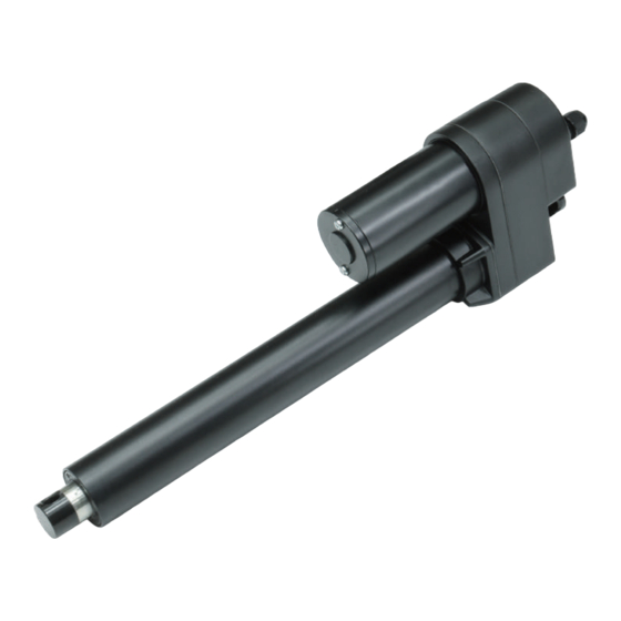
Industrial Actuator
CAUTION:
CAUTION:
ADJUST THE LIMIT SWITCHES
!
NOTICE
●
Limit switch adjustment shall apply only to products that are not IP65 protected. Besides, IP protection
will be void once the back cover is removed.
●
Before the actuator is powered, it's necessary to put a bolt through the front connector to keep
the inner tube from self-spinning, which ensures proper correlation between the limit switch and stroke.
●
The upper cam sets the most extended position, and the lower cam sets the most retracted position.
The adjustment shall be made within the specified stroke, to avoid having the related parts damaged.
●
The fine-tuning screw shall not be too much turned, to avoid damaging the plastic components.
●
Make sure the upper and lower cams are held in place, when you try to fasten or unfasten the cam
screw. Do not remove the cam screw entirely, or otherwise the cam limit assembly will be damaged.
HOW TO ADJUST THE CAM LIMIT SWITCH?
Step 1:
The actuator has to be at no load condition, off from any frame. Loosen the cable gland with a
wrench, and remove the 3 screws on the back cover. Slowly remove the back cover, and be
careful not to damage the gasket inside.
Step 2:
As per the info in Notice, keep the inner tube from self-spinning. Connect the actuator to power,
and retract it to the lower limit position, where the limit switch is reached, and motor stops itself.
This is the default position of the lower limit. To adjust this position, turn the inner tube manually,
towards the direction of extension, instead of the direction of retraction.
Model: ID11
KG
LOAD
The load should be centered on the
operating direction.
Side load is NOT good for actuators.
KG
Side Load
R
MOTORIZE OUR WORLD
Advertisement
Table of Contents

Related Manuals for MOTECK ID11


Summary of Contents for MOTECK ID11
- Page 1 User Guide MOTORIZE OUR WORLD Industrial Actuator Model: ID11 CAUTION: CAUTION: LOAD The load should be centered on the operating direction. Side load is NOT good for actuators. Side Load ADJUST THE LIMIT SWITCHES NOTICE ● Limit switch adjustment shall apply only to products that are not IP65 protected. Besides, IP protection will be void once the back cover is removed.
- Page 2 © 2018 Moteck. Printed in Taiwan. The contents of this publication are the copyright of the publisher and may not be copied or even extracted unless prior written permission is authorized.
Need help?
Do you have a question about the ID11 and is the answer not in the manual?
Questions and answers