Table of Contents
Advertisement
Quick Links
Advertisement
Table of Contents

Related Manuals for hager HTD210H


Summary of Contents for hager HTD210H
- Page 1 User manual h3+/hw+ Panel display HTD210H...
-
Page 3: Table Of Contents
Contents Safety symbols Safety instructions Disposal and recycling information About this manual HTD210H panel display Components overview Menu functions Technical specifications Dimensions and cut-outs Cables and accessories Connection and power supply Connection to an h3+ Energy circuit breaker Connection to an hw+ sentinel Energy circuit breaker... - Page 4 Configuration menu Submenus Navigation and setting Submenus contents Information menu Submenus Navigation in the circuit breaker information submenu Navigation in log of alarm events and log of trip events Submenus contents 10 Support 11 Appendix Subject to technical changes...
-
Page 5: Safety Symbols
Safety symbols Safety symbols This documentation contains safety instructions you must observe for your personal safety or for the prevention of damage to property. The safety instructions referring to your personnel are indicated in the documentation by a safety alert symbol. The safety instructions referring to property damage are indicated by the mention NOTICE. -
Page 6: Safety Instructions
The product or system described in this documentation should be installed, operated and maintained only by qualified staff. No responsibility is assumed by Hager for any consequences arising out of the use of this equipment by unqualified staff. Qualified personnel are those people who have the necessary skills and knowledge for building, operating and installing electrical equipment, and who have received training enabling them to identify and avoid the risks incurred. -
Page 7: Disposal And Recycling Information
Disposal and recycling information Disposal and recycling information The disposal of the HTD210H panel display must be done in accordance with the regulations in force in the country concerned. Because it contains electronic components, the panel display must be processed separately from household waste. - Page 8 Subject to technical changes...
-
Page 9: About This Manual
This document provides information about configuration and operation of the HTD210H panel display. Validity scope This document applies to the HTD210H panel display used with h3 + Energy moulded case circuit breakers and hw+ air circuit breakers equipped with the sentinel Energy electronic trip unit. - Page 10 About this manual Related documents Document title Reference HTD210H panel display installation instruction 6LE002194A h3+ Moulded Case Circuit Breakers up to 630 A Technical catalogue 6LE005047A h3+ Communication System manual 6LE002998A HW1/HW2/HW4 air circuit breakers technical catalogue 6LE007334A Installation manual for HW1 air circuit breakers...
-
Page 11: Htd210H Panel Display
The HTD210H panel display is mainly intended for visualising measurements, defining protection settings and managing alarms. The HTD210H panel display is usually mounted on the door of a control cabinet or a panel where the connected circuit breaker is installed. -
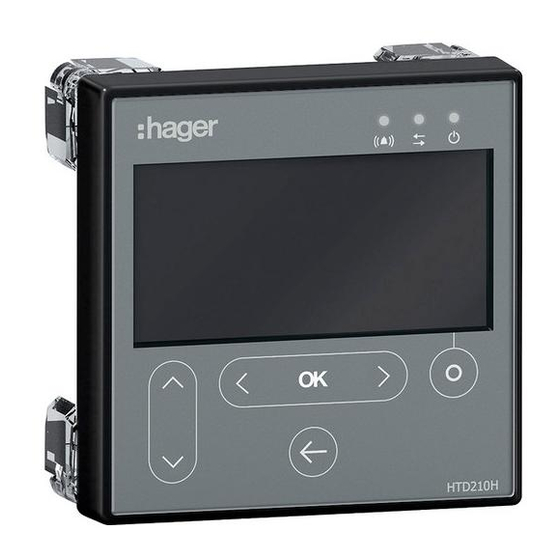
Page 12: Components Overview
HTD210H panel display 2.1 Components overview Display part Description Display LCD display Alarm – Communication – Operational RJ9 connector Used to connect the cable between the h3+ Energy circuit breaker or the hw+ Energy air circuit breaker and the display. - Page 13 HTD210H panel display Display The display provides different screen views, depending on the corresponding functions: Display Menu Main menu Alarm pop-up window Live mode Menu (e.g. measure) Standby function By default the backlight of the display is always on. It can be deactivated in the Configuration menu.
- Page 14 HTD210H panel display Description Behaviour Alarm with medium and high priority. flashing red Communication with the circuit breaker. flashing yellow The device is supplied with power and is ready. Green External ports External port Description Display Communication connection with the circuit breaker and the power supply of the display (RJ9 connector).
-
Page 15: Menu Functions
HTD210H panel display 2.2 Menu functions Overview of the available menu functions of the HTD210H panel Display. Display Menu Functions Live mode Standard view of the display - Visualisation of selected measurements (favourites). Main menu - Accessing the menus. Measurement - Visualisation of all measurements. - Page 16 HTD210H panel display The following table describes what functions are available depending on the type of circuit breaker connected, either h3+ Energy, or hw+ sentinel Energy. h3+ Energy hw+ sentinel Energy Read Write Read Write Function access access access access...
- Page 17 HTD210H panel display Only the menus corresponding to the functions available are displayed with an hw+ sentinel Energy circuit breaker. In addition, the menus and displays of the panel display connected to the hw+ sentinel Energy circuit breaker will be available or not according to the type of rating plug installed (refer to the hw+ sentinel Energy circuit breaker electronic trip unit user manual).
-
Page 18: Technical Specifications
HTD210H panel display 2.3 Technical specifications Electrical characteristics Rated supply voltage DC 24 V (+/- 30 %) SELV Current consumption 85 mA Environmental and mechanical characteristics Operating temperature range -10 °C…+55 °C Storage temperature -20 °C…+70 °C Pollution degree Installation category... -
Page 19: Dimensions And Cut-Outs
HTD210H panel display 2.4 Dimensions and cut-outs Dimensions Width (mm) Height (mm) Depth (mm) HTD210H 18 (45) Panel cut-out up to 8 Subject to technical changes... -
Page 20: Cables And Accessories
HTD210H panel display 2.5 Cables and accessories For an h3+ Energy circuit breaker Electrical power supply by CIP Electrical power supply via communication module. 1 CIP 24 V Adapter 2 CIP adapter for h3+ 3 Modbus RTU h3+ communication module... - Page 21 HTD210H panel display For an hw+ sentinel Energy 1 HWY210H adapter 2 Power supply 230 V AC / 24 DC Reference Description HWY210H RJ9 adapter for panel display Subject to technical changes...
- Page 22 Subject to technical changes...
-
Page 23: Connection And Power Supply
Risk of damaging the HTD210H panel display Using the wrong adapter may result in damaging the device. ¾ Connect socket HTD210H panel display HTD210H to an h3+ Energy circuit breaker only with an original CIP Hager HTC3xxH adapter. ¾ Connect socket HTD210H panel display to an hw+ sentinel Energy circuit breaker only with an original Hager HWY210H adapter. -
Page 24: Connection To An H3+ Energy Circuit Breaker
Place the cable outside the circuit breaker. - Make sure not to pinch the cables. Lead the cable to the HTD210H panel display. Connect the RJ9 plug of the CIP adapter to the socket named "Display" on the back of the HTD210H panel display. - Page 25 ¾ Use only the original Hager HTC3xxH CIP adapters to connect and power the HTD210H panel display. The 24 V DC electrical power supply of the HTD210H panel display must be connected directly to the h3+ Energy circuit breaker. It is extended to the panel display via the CIP adapter HTC3xxH.
- Page 26 5 Electrical power supply HTG911H connect to the panel display 2 CIP connector of the CIP adapter to 6 HTD210H panel display connect to the communication module 3 CIP adapter to connect to the Modbus 7 CIP adapter to connect to the panel...
- Page 27 2 Powering the Panel display directly via an external electrical power supply 1 CIP connector of the CIP adapter to 5 HTD210H panel display connect to the panel display 2 CIP connector of the CIP adapter to 6 CIP adapter to connect to the panel...
-
Page 28: Connection To An Hw+ Sentinel Energy Circuit Breaker
3.2 Connection to an hw+ sentinel Energy circuit breaker ATTENTION Risk of damage to electronic devices Voltage over 32 V DC will cause damage to the HTD210H panel display. ¾ Use only original Hager HWY210H adapters to connect and power the HTD210H Panel display. -
Page 29: First Power-Up
Connection and power supply 3.3 First power-up When first powered up, the panel display starts with the language settings menu after having displayed the startup screen. The default language is English. If this is appropriate, confirm with the OKkey. Changing the language: Button Step/Action Display... - Page 30 Subject to technical changes...
-
Page 31: Display Modes And Navigation
Display modes and navigation Display modes and navigation This chapter gives an overview of the display modes and navigation within Live mode and the Main menu. 4.1 Navigation Display principle The display principle is nearly identical within all menus. Submenus Padlock symbol: Menu is protected Name of menu Icon of menu... - Page 32 Display modes and navigation Information window The information window displays several types of information depending on the selected submenu: Settings within submenus Information Second level submenus All inputs are done using the touch keys. Button Name Description Contextual - Functionality depends on the displayed menu - Left and right navigation within menus and submenus.
-
Page 33: Start-Up Screen
Display modes and navigation 4.2 Start-up screen The panel display starts as soon as it is powered up. If the communication with the circuit breaker is operational, the start-up screen is displayed and the communication between the display and the circuit breaker is tested. While the start up screen is displayed, the panel display is fetching its configuration settings stored in the circuit breaker. -
Page 34: Live Mode
Display modes and navigation 4.3 Live mode After start-up or if there is no user action within a menu for 2 minutes, the display switches automatically to Live mode. Live mode displays the measurement screen views set as favourites in the Measure menu. - Page 35 Display modes and navigation Display options within Live mode The various representation options below are available for the display of currents, voltages and powers: Value Bar graph Gauge To change the type of the representation use the left or right keys. NOTE The representation chosen in the Live mode menu is automatically applied to the relevant screen view in the Measure menu.
- Page 36 Display modes and navigation Bluetooth signalling in Live mode With the hw+ sentinel Energy circuit breaker the icon is displayed in Live mode when the circuit breaker's Bluetooth communication is activated. Subject to technical changes...
-
Page 37: Main Menu
Display modes and navigation 4.4 Main menu The Main menu gives access to the menus. By default, the Measurement menu is preselected. There are 5 menu items: Symbol Menu Functions Protection - Display and setting of the protection parameters. - Display of the available measurements. Measurement - Setting favourites. - Page 38 Display modes and navigation Opening the Main menu from Live mode Button Step/Action Display Stopping Live mode. - The Main menu opens with the Measurement menu preselected. Selecting and opening a menu Button Step/Action Display Select a menu. Open the menu. Subject to technical changes...
-
Page 39: Locked/Unlocked Mode
Resetting min/max measurements Erasing alarms and trip events Password The HTD210H panel display is delivered with the predefined password '3333'. If the predefined password is not working, refer to your delivery documents for the predefined password. Subject to technical changes... - Page 40 Display modes and navigation Unlocking a menu or function using the password 1-2-3-4, for example Button Step/Action Display Open the Main menu. - The closed padlock indicates that the display is locked. Open the menu for entering the password. - The password consist of 4 digits. Increase / decrease the value of the digits.
-
Page 41: Alarm Warnings
Display modes and navigation 4.6 Alarm warnings Optional alarm or trip display priorities The panel display manages the alarm warnings according to their level of priority: Actions Stored as alarm Stored in active Alarm pop-up Alarm LED Priority event alarms list* window** flashing Average... - Page 42 (default value: 90 % Ir). Trip Test On 08/06/2018 at 10h44 am, a trip test was carried out with the Hager Power setup software. Custom alarm no. 1 Occurred on 06/03/2018 at 14:18; voltage on phase L2, V2 >...
- Page 43 Display modes and navigation Active alarms list All descriptions of active alarms with medium or high level of priority are accessible in the active alarms list using the Contextual key. High priority level active alarm pop-ups can be recalled after having been acknowledged using the Contextual key when the alarm icon is displayed.
- Page 44 Subject to technical changes...
-
Page 45: Protection Menu
Protection menu Protection menu This chapter gives an overview of the protection settings menu and the parameters of the connected circuit breaker. 5.1 Submenus In the Protection menu the protection settings of the connected circuit breaker can be displayed and modified. The modification of these settings is protected by a password, refer to Locked/ Unlocked mode on page 39. - Page 46 Protection menu The following submenus are also available with an hw+ sentinel Energy circuit breaker equipped with an "Advanced" or "Ultimate" rating plug. Submenus Attribute Undervoltage protection - ANSI 27 Overvoltage protection - ANSI 29 Underfrequency protection - ANSI 81L Overfrequency protection - ANSI 81H Reverse active power protection - ANSI 32R Phase unbalance protection - ANSI 46...
-
Page 47: Navigation And Modifying Settings
Protection menu 5.2 Navigation and modifying settings NOTE The Display must be in Unlocked mode for modifying the settings, refer to Locked/ Unlocked mode on page 39. Button Step/Action Display Open the Protection menu. Select a submenu. - The selected submenu is highlighted. -
Page 48: Submenus Contents
Protection menu 5.3 Submenus contents Content for the h3+ Energy circuit breaker Attribute Parameter Unit Description Range dependent on In rating, set in increments of 1. 0.5, 1.5, 2.5, 5.0, 7.5, 9.0, 10.0, 12.0, 14.0, 16.0 x Ir 1.5 to 10 in steps of 0.5; Off; default enabled, if disabled, tsd and I2t short will be hidden. - Page 49 Protection menu The following submenus are also available with an hw+ sentinel Energy circuit breaker equipped with an "Advanced" or "Ultimate" rating plug. They are only available on a read-only basis. Parameter Unit Description Configuration Off, Trip, Alarm Inhibit Off or On Voltage monitoring L-L or L-N Activation threshold...
- Page 50 Subject to technical changes...
-
Page 51: Measurement Menu
Measurement menu Measurement menu This chapter gives an overview of the Measurement menu contents of the connected circuit breaker. 6.1 Submenus In the Measurement menu, most measurements of the corresponding circuit breaker can be displayed. NOTE The display of the individual measured values (value, bar graph or gauge), depends on the favourite settings specified in the Measurement menu or in Live mode. - Page 52 Measurement menu Available submenus Symbol Functions Current measurements Phase-to-phase voltage measurements Phase-to-neutral voltage measurements Active power, reactive power, apparent power and maximum values Power demand (averaged values) Power factor and cos φ Total harmonic distortion Energy Active tariff energy meters (available only with the hw+ sentinel Energy circuit breaker equipped with a "Meter Plus", "Harmonic", "Advanced"...
-
Page 53: Navigation Within The Measurement Menu
Measurement menu 6.2 Navigation within the Measurement menu Navigation in the Measurement menu is done vertically to select a submenu. Navigation in a submenu is done horizontally to select a specific section. Submenus - The selected submenu icon is highlighted. - To navigate: Labels of screen view - The selected screen view label is highlighted. -
Page 54: Setting Favourites And Representation
Measurement menu 6.3 Setting favourites and representation Each screen view can be selected as a favourite to be displayed in Live mode. The following screen views are selected as default favourites and are displayed in Live mode. Setting favourites Button Step/Action Display Open the Measurement menu... - Page 55 Measurement menu Changing the representation For most of the screen views, the following 3 representation options are available: Digital Gauge Bar graph Button Step/Action Display Open the Measurement menu Select a submenu. - The selected submenu icon is highlighted. Select the desired screen view. - The selected screen view label is highlighted.
-
Page 56: Measurement Parameters
Measurement menu 6.4 Measurement parameters Current inst stat misc [A]: rms current I1, [A]: last maximum [A] avg: arithmetic [%]: Unbalanced [A] max: last I2, I3 and IN (neutral) rms current I1, I2, mean current of I1, I1, I2, I3, IN vs. maximum current I3 and IN (neutral) I2 and I3... - Page 57 Measurement menu Voltage – Phase to neutral inst [V] V1N: rms phase [V] V1N: last [V] V1N: last [%] V1N: [V] V: arithmetic 1 to neutral voltage. maximum rms of minimum rms of unbalanced V1N mean of V1N, V2N V1N (timestamp); V1N (timestamp);...
- Page 58 Measurement menu Power factor φ Pow. Fact. φ φ φ PF1, PF2, PF3: power factor per phase 1, cos 2, cos 3: fundamental power factor per phase PF tot: total power factor φ Tot: total fundamental power factor Total harmonic distortion U [%] V [%] I [%]...
- Page 59 Measurement menu Network Network Frequency [Hz] Quadrant: Power quadrant Rot. field: current order of phases 1, 3, 2 or 1, 2, 3. Subject to technical changes...
- Page 60 Subject to technical changes...
-
Page 61: Alarms Menu
Alarms menu Alarms menu This chapter gives an overview of the Alarms menu. Setting and editing alarms will be explained. 7.1 Submenus In the Alarms menu the following parameters can be set and modified: Custom or optional alarms Overload prealarm Trip alarms OAC output contact The modification of these settings is protected by a password, refer to Locked/... - Page 62 Alarms menu Submenu Attribute Custom or optional alarm - Up to 12 alarms can be defined to monitor a measurement event by definition of thresholds and time delays. Several parameters allow to set the condition for activation and the priority level. Overload prealarm - The PTA or PTA1 overload prealarm is a predefined alarm that determines the behaviour of the PTA LED on the h3+ Energy circuit breaker and its PTA...
-
Page 63: Navigation And Setting
Alarms menu 7.2 Navigation and setting NOTE The display must be unlocked to set alarms, see Locked/Unlocked mode on page 39. Displaying and setting custom alarms Button Step/Action Display Open the Alarms menu. Select "Custom" - All configured or unconfigured alarms are displayed. Confirm your selection. - Page 64 Alarms menu Button Step/Action Display Select and set the alarm activation condition (Option 2). Select and configure the alarm priority (only for h3+ Energy circuit breakers). 10. Select and set activation thresholds and time delays: - threshold: Pick-up value - threshold: Drop-out value - time delay: Pick-up delay - time delay: Drop-out delay Confirm the settings.
- Page 65 Alarms menu Displaying and setting overload prealarms. Button Step/Action Display Open the Alarms menu. Select "PreTrip" (overload prealarm). - The selected submenu icon is highlighted. - The adjustable parameters are displayed in the information window. Confirm your selection. - The threshold parameter is highlighted.
- Page 66 Alarms menu Button Step/Action Display 10. Confirm the overload prealarm time delay. - The new parameters for the alarm type are set. 11. Return to the Alarms menu. Subject to technical changes...
- Page 67 Alarms menu Displaying and setting Trip alarms Button Step/Action Display Open the Alarms menu. Select trip. - The selected alarm type is highlighted. - The adjustable parameters are displayed in the information window. Confirm your selection. - The first parameter is highlighted.
- Page 68 Alarms menu Displaying and configuring the OAC output contact Button Step/Action Display Open the Alarms menu. Select OAC. - The selected submenu icon is highlighted. Confirm your selection. - The assignment parameter is highlighted. Confirm the selection of the assignment parameter. - The assignment pop-up window is displayed.
-
Page 69: Submenus Contents
Alarms menu 7.3 Submenus contents NOTE The measurement attributes within the "Custom" submenu depend on the 3-pole/4- pole configuration of the circuit breaker. Therefore not all combinations of the listed parameters are always possible. Type of measurement Option 1 (measurement attribute) Option 2 (alarm activation condition on Option 1) Current... - Page 70 Alarms menu Parameter Description Assignment Default overload prealarm; to assign an alarm* to the OAC output contact of the h3+ Energy circuit breaker. Reset mode Locking / Automatic; Set behaviour of OAC contact; Locking: acknowledgement required through Modbus to set OAC contact back to normal position;...
-
Page 71: Configuration Menu
Configuration menu Configuration menu This chapter gives an overview of the Configuration menu and the adjustable param- eters of the connected circuit breaker. 8.1 Submenus The settings are password protected, refer to Locked/Unlocked mode on page 39 to unlock the function. Subject to technical changes... - Page 72 Configuration menu Available submenus Submenus Function Setting the display Date and time setting Changing the password Setting the measurements Resetting min/max measurements Erasing custom alarms Erasure of trip events Subject to technical changes...
-
Page 73: Navigation And Setting
Configuration menu 8.2 Navigation and setting The following example explains how to adjust the settings in the Configuration menu in general. The individual settings for each parameter may differ. Button Step/Action Display Open the Configuration menu. Select a submenu. - The selected submenu is highlighted. -
Page 74: Submenus Contents
Configuration menu 8.3 Submenus contents NOTE Except for the Display settings submenu, the display must be unlocked before changes are possible, refer to Locked/Unlocked mode on page 39. Display settings Parameter Description Values Brightness Setting for the brightness of the 20 – 100 % (increment 20) display. - Page 75 Configuration menu Measurement parameters Parameter Description Values Phase sequence Defining the sequence of the L1>L2>L3 / L1>L3>L2; connected phases. default value: L1>L2>L3 NSP (only on h3+ Energy Defining the topology of the connected circuit breaker) phases. 3P/3P+N (On 3P circuit breakers only 3P topology is available).
- Page 76 Configuration menu Reset of all minimum and maximum measurement values Category Description Reset all min / max Reset of all the min / max values. Reset current min / max Reset of current min / max values. Reset voltage min / max Reset of voltage min / max values.
-
Page 77: Information Menu
Information menu Information menu This chapter gives an overview of the Information menu and the information dis- played. 9.1 Submenus The Information menu displays various kinds of information about the connected circuit breaker In this menu no user inputs or adjustments are possible. Only information is displayed. -
Page 78: Navigation In The Circuit Breaker Information Submenu
Information menu 9.2 Navigation in the circuit breaker information submenu Button Step/Action Display Open the Information menu. Scroll up and down to view more entries and their information or status. Return to the Information menu. Subject to technical changes... -
Page 79: Navigation In Log Of Alarm Events And Log Of Trip Events
Information menu 9.3 Navigation in log of alarm events and log of trip events Button Step/Action Display Open the Information menu. Select the log of alarm events submenu or the log of trip events submenu. - The selected submenu is highlighted;... -
Page 80: Submenus Contents
Description Description of the circuit breaker saved after commissioning with the Hager Power setup software. Settings Date of last commissioning with the Hager Power setup software. Product code Product code of the circuit breaker. Last maintenance Date of the last maintenance. - Page 81 The history of trip alarms is sorted from latest (rank 1) to earliest (rank up to 10). For date and time of the alarm event, select the alarm and use the OK key. Serial number Serial number of the HTD210H panel display Subject to technical changes...
- Page 82 Subject to technical changes...
-
Page 83: Support
- Check the CIP adapter between display and circuit breaker by replacing it. - Reconnect the panel display. - Get in touch with your Hager contact if the message is still present. Flashing - Check the compatibility of the circuit breaker with the current panel display. - Page 84 If your password is lost, the panel display can be unlocked by creating a new password with the Hager Power setup software. To do this connect the Hager Power setup software to the circuit breaker. Go to the Settings>Passwords in the application For the hw+ sentinel Energy circuit breaker, click "Reset".
-
Page 85: Appendix
Appendix 11 Appendix Information on the software licences for the HTD210H panel display STM32F10x, STM32L1xx, STM32F3xx USB FS DEVICE Driver Copyright: Copyright 2012 STMicroelectronics License: SLA0044 License Text: SLA0044 Rev5/February 2018 BY INSTALLING COPYING, DOWNLOADING, ACCESSING OR OTHERWISE USING THIS SOFTWARE OR ANY PART THEREOF (AND THE RELATED DOCUMENTATION) FROM STMICROELECTRONICS INTERNATIONAL N.V, SWISS BRANCH AND/... - Page 86 Support 8. The recipient shall comply with all applicable laws and regulations affecting the use of the software or any part thereof including any applicable export control law or regulation. 9. Redistribution and use of this software or any part thereof other than as permitted under this license is void and will automatically terminate your rights under this license.
- Page 87 Support 3. Neither the name of STMicroelectronics nor the names of other contributors to this software may be used to endorse or promote products derived from this software or part thereof without specific written permission. 4. This software or any part thereof, including modifications and/or derivative works of this software, must be used and execute solely and exclusively on or in combination with a microcontroller or microprocessor device manufactured by or for STMicroelectronics.
- Page 88 SOFTWARE, EVEN IF ADVISED OF THE POSSIBILITY OF SUCH DAMAGE. For third party technology that you receive from Hager Group or its affiliates in binary form which is licensed under an open source license, you can receive a copy of this...
- Page 89 (ii) in the case of code licensed under the GPL v3, for as long as Hager sales this product or customer support for that product in the country of the requester.
- Page 90 Support (i) create, edit, view, print and distribute materials, provided that, (a) if you distribute such materials, the mate-rials do not contain the Font Software, and (b) if you create a static graphic image with a representation of a typeface and typographic design or ornament, such static graphic image does not correspond to glyphs or glyph combinations of the Font Software which are individually addressed by software, a website, a hard-ware device or other means to render such designs and ornaments;...
- Page 91 Support • Transfer your license rights in the Font Software, except as expressly provided herein. You may transfer all your rights to use the Font Software to another person or legal entity provided that (i) the transferee accepts and agrees to be bound by all the terms and conditions of the Agreement, (ii) you destroy all copies of the Font Soft-ware, including all copies stored in the memory of a hardware device and (iii) there is no change to the intent or scope of the rights granted by this Agreement as...
- Page 92 Support 6. Limited Warranty; Limitation of Liability. Monotype warrants to you that the Font Software will effect a faithful repro-duction of the underlying typeface design which is of a quality consistent with industry standards. To make a warranty claim, you must notify Monotype in text form within the Warranty Period, which could include via an email to warran-ty@monotype.com and provide sufficient information regarding your licensing of the Font Software so as to enable Monotype to verify...
- Page 93 Support “Font Software” means software or instructions which, when used on an appropriate device or devices, generates typeface and typographic designs and ornaments. Font Software shall include all Subsets and bitmap representations of typeface and typographic designs and ornaments created by or derived from the Font Software. Font Software includes upgrades or updates (each of which may be provided to you by Monotype in its sole discretion), related files, permitted modifications, permitted copies, and related documentation.
- Page 94 Subject to technical changes...
- Page 95 Subject to technical changes...
- Page 96 Hager Electro SAS 132 Boulevard d’Europe 67210 OBERNAI CEDEX www.hager.com 6LE002999Ab...
Need help?
Do you have a question about the HTD210H and is the answer not in the manual?
Questions and answers