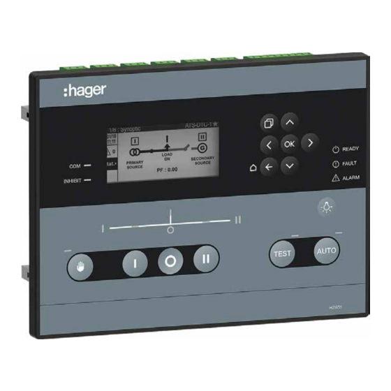
hager HZI855 Instruction Manual
Automatic transfer switching controller
Hide thumbs
Also See for HZI855:
- Quick start manual (7 pages) ,
- Installation and commissioning manual (8 pages)

Related Manuals for hager HZI855


Summary of Contents for hager HZI855
- Page 1 Automatic Transfer Switching Controller Instruction manual HZI855 http://hgr.io/r/hzi855 6LE007317A...
- Page 2 Index 1. General Safety Instructions 2. Standards 3. Introduction 4. General overview 5. Environmental 5.1. IP Rating 5.2. Operating Conditions 5.2.1. Temperature 5.2.2. Hygrometry 5.2.3. Altitude 5.3. Storage Conditions 5.3.1. Temperature 5.3.2. Hygrometry 5.3.3. Storage duration period 5.3.4. Storage position 5.3.5.
- Page 3 11. Configuration 11.1. Configuration through the display 11.1.1. NETWORK parameters menu 11.1.2. DISPLAY parameters menu 11.1.3. TIMERS parameters menu 11.1.4. I/O parameters menu 11.1.5. COMMUNICATION parameters menu 11.1.6. ALARMS parameters menu 11.1.7. PASSWORDS 11.1.8. SPECIFIC FUNCTIONS Menu 11.1.9. Maintenance Menu 12.
-
Page 4: General Safety Instructions
RISK: Electric shock, burns, death • Whether the HZI855 is sold as a loose product, as a spare, in a kit or as part of an enclosed solution or in any other configuration, this device must always be installed and commissioned by qualified and... -
Page 5: General Overview
4. General overview HZI855 ATS Controller reference includes: - 1 HZI855 Controller - 1 door mounting kit - 1 backplate mounting kit - Quickstarts instruction sheet. All other components described in this instruction manual are available as accessories and sold separately. -
Page 6: Operating Conditions
• Weight: net 1.060 kg/ gross 1.500 kg 6. Standard compliance and marking Lead free Cmim CE marking process WEEE • HZI855 is built in accordance with 2012/19/EU directive: Standards compliance Certified according to: IEC 61010-2-201 IEC 61010-1 GB/T 14048.11 Annex C Conform to the requirements of: IEC 60947-6-1 when used with an IEC 60947-6-1 certified RTSE (Remotely operated transfer switch). -
Page 7: Door Mounting
7.1. Product dimensions (dimensions in mm.) 7.2. Mounting HZI855 can be mounted either on the door or on the backplate of an enclosure (both mounting kits are delivered with the product). 7.2.1. Door mounting HZI855 can be mounted on doors up to with a thickness 4mm. - Page 8 STEP 2: Fixing the controller on the door: Place the ATS controller inside the door cut-out and clip the door mounting screws into the side of the controller (2 screws on each side). It is important to respect the tightening torque indicated below and follow good engineering practise when installing the ATS controller.
- Page 9 STEP 2: Fixing the controller on the backplate Drill mounting holes in the backplate to match the fixing holes as shown and indicated below. Fix the controller through the mounting legs to the backplate with a maximum screw diameter of 6mm. 6LE007317A...
-
Page 10: Terminal Connections
7.3. Terminal Connections Top view: Right side view: Bottom view: To help secure the control cables during the wiring, the controller includes seven fixing supports on the back of the controller to retain the cables in place using cable ties. 6LE007317A... - Page 11 N° Denomination Terminal Description Characteristics Recommended Cable Section Voltage sensing L1 / A Phase 1 / A 1Ph / 3Ph source 1 50 … 332 / 575 VAC 1 … 2.5 mm² L2 / B Phase 2 / B (50/60 Hz) Tightening torque (+/- 10%) L3 / C...
- Page 12 7.3.1.2. DC Power Supply HZI855 controller includes an optional DC power supply input to power the controller in case both sources are off. The DC power supply voltage needed to power up the controller is between 9 VDC and 28 VDC.
- Page 13 7.3.1.3. Command circuits By default, the inputs and outputs in the HZI855 are set up as follows: Configuration changes when changing By default RTSE technology Type Terminal N° Description Breakers HIB4xxM Contactors IN1: programmable input Breaker 1 is in position ON...
- Page 14 Open* * HZI855 controller includes two bi-stable relays with backup energy, when the controller loses all sources of power supply outputs 5 and 6 will automatically activate (NO contact will close and NC contact will open). This is a safety feature designed to ensure power availability to the load in Main-Genset or Genset-Genset application by forcing generators to start in case of total power loss.
- Page 15 8. First power up - Smart Wizard Once the controller is connected to the switch with the cable harness, as soon as the controller is powered up, it will automatically start in MANUAL mode and, in order to facilitate the commissioning, a smart wizard will appear to drive the user through the main configuration parameters.
- Page 16 Once the configuration starts, the user needs to enter the date format, date and time as follows: These time/date values will be saved and from that moment the RTC battery will keep the clock running even if the supply to the controller is lost.
- Page 17 The 7th step is not affecting the functioning of the transfer switch but permits the user to select a name for the product. As default, it’s HZI855, but it can be changed for any combination of letters, numbers and signs, for instance, “Cooling”, “Line 1” or “DTC/21”.
-
Page 18: Product Name
9. Visualisation options The visualisation DASHBOARDS The controller has a direct access button to the visualization dashboards on the front face. The dashboards can be accessed by short pressing the key. By pressing again we switch from one dashboard to another and inside each dashboard there might be different number of screens as it is shown on the image below. - Page 19 STATUS: Give more detailed information on the sources STAT.: Informs the user on the availability of each source. SYNC: Information on the voltage, frequency and phase angle of both sources. HZI855 HZI855 METERING: Allows the user to visualize detailed metering information on the load side.
- Page 20 TIMERS: Allows the user to visualize the status of the timers. RUN: Shows all the ongoing timers, and allows the user to bypass the timers S1: Shows all timers linked to source 1 S2: Shows all timers linked to source 2 OPT: Shows all optional timers ALARMS: Allows the user to visualize active and finalized alarms.
- Page 21 The visualisation pop-up: The controller will inform the customer about the main real-time events through a pop-up. This pop-up can have 2 types of purpose: - CURRENT ACTIVE TIMER: timer pop-ups show the name of the timer active, the configured value and the countdown value with double font.
-
Page 22: Operation And Control
10. Operation and control 10.1. HMI use On the front face of the controller there are 14 keys/buttons that are used to configure, operate and visualize the ATS values anytime. Summary of the HMI buttons: 1 Manual operation buttons and indicator. 2 Test button and indicator. -
Page 23: Navigation Menu
10.2. Navigation Menu The Menu on the display can be access with the Return/Menu button on the front face of the controller. It is structured in different chapters and is easy to navigate through it with the navigation pad. To select a screen use the navigation arrows , then press the ok key to validate the selected screen. - Page 24 TEST: it allows the maintenance person to perform a transfer to Source 2 and to decide when to go back to the Source 1. The testing of the ENGINE START can be performed using a TEST OFF LOAD test in the menu or assigning the TEST button to this function. The TEST mode can be launched from both MANUAL or AUTOMATIC modes.
- Page 25 The synoptic on the HZI855 controller informs the user on the status of the sources: The round green LED next to S1 or S2 indicates if the source is available or not: - If the LED is on but not blinking then the source is considered as available.
-
Page 26: Test Operating Mode
There are 3 type of commands available in the control menu and all of them require the operator profile password. Those commands are: HZI855 MODE / POSITION: permits changing the operating mode, change position in CTRL mode and start/stop the gensets remotely (also in... - Page 27 HZI855 EVENTS LOG: HZI855 can store up to 300 events using FIFO to replace older events when the memory is full. The event log will show the information of virtually everything happening on the controller/ATS with timestamp and description. To navigate through the event log, the UP and DOWN arrows can be used to advance on the event list one by one and the LEFT and RIGHT arrows to advance 6 events every time.
- Page 28 2 options: in progress and history. “In progress” shows all active alarms and the history shows all the last finalized alarms. HZI855 For each alarm, unlike with the events, the details are available, permitting the user to see: •...
- Page 29 • Source 1 / Source 2 data (total time in source, partial time, last switch, total time on load) • Genset 1 / Genset 2 data (total active time, total active time on load, genset start counter) HZI855 10.8. Genset scheduler / Engine Exerciser Menu There are 4 selectable engine exerciser programs that are set in order of priority on the display.
- Page 30 Ending time&date: that’s the date&hour where the program will stop (for example, May 12th at 4pm) (after this date, this program will not execute a TEST). Current Behaviour : Problem when 2 or more Custom exerciser of same type (TON or TOF) ov HZI855 TON Custom 1 : Duration 50 minut TON Custom 1 : Duration 30 minutes...
-
Page 31: Parameters Menu
11. Configuration The configuration on the HZI855 can be done directly on the HMI. NOTE: The configuration can be done even without cabling the AC or DC supply to the controller, only connecting it to a computer with an USB cable. The controller will use the USB to power up the screen, buttons and main functions, permitting the configuration through any of these methods. - Page 32 The NETWORK menu allows the user with the Configurator profile to configure the installation parameters. Inside NETWORK, there are 5 different submenus: HZI855 AUTODETECT.: When selected the function, a pop-up will show asking for a validation from the user to start autodetecting the network type, the nominal voltage and frequency and the phase rotation.
-
Page 33: Application Type
OFF), offering the option to have 3 positions when used as a transfer switch (I-0-II). • HIB4xxM (remote / double supply) makes reference to HIB4xxM Hager switches. • CONTACTOR - (circuit contactor) makes reference to standard IEC 60947-4-1 contactors with 2 positions per device (ON and OFF), offering 3 positions (I-0-II). - Page 34 U 13 3’ U 1’3’ 1’ N’ U 32 U 21 U 3’2’ U 2’1’ 2’ Balanced network Unbalanced network For each parameter, the limits can be set in % vs the nominal value and there are two parameters to set: the tripping value that will make the source be considered unavailable (FAIL) and the value that will make the source be considered available again (RESTORE).
- Page 35 Types of Network 1P+N Single phase network Source 1 Source 2 Load 2P+N Two phase network with neutral Two phase network without neutral Source 1 Source 2 Source 1 Source 2 Load Load 3P+N Three phase network with neutral Three phase network without neutral Source 1 Source 2...
- Page 36 Metering and sensing details Network type 2P+N 3P+N 3P+N 3P+N / 1P+N 3 phase Source 1 4 wire 1 phase 2 phase 2 phase 3 phase 3 phase 2 wire 2 wire 3 wire 3 wire 4 wire 1 phase Source 2 2 wire Source 1...
-
Page 37: Screen Parameters
“Timeout” sets the time in seconds where the screen will remain on after touching a button. DATE AND TIME PARAMETERS: HZI855 Date and time will remain running thanks to the RTC battery even if all sources are off. OPTIONS for the HMI buttons: HZI855 •... - Page 38 NOTE: The specific functions with timers are not included in this chapter. Consult the Timers Annex II in chapter 13.2 to have the full list. Operation timers (6 timers): HZI855 • FAILURE TIMER (s): time after source is lost, to make sure it’s really lost and start a transfer.
- Page 39 All the I/O can be set on this menu. By default, the controller has 6 inputs and 6 outputs on the controller (called internal Inputs / Outputs). The I/O menu has the following submenus: INPUTS: permits configuring the 6 internal inputs HZI855 OUTPUTS: permits configuring the 6 internal outputs HZI855 Consult the I/O Annexes in chapters 13.3 and 13.4 to have the full list of functions to be configured on the I/O.
- Page 40 11.1.5. COMMUNICATION parameters menu RS485 The MODBUS RTU protocol available on the HZI855 communicates via an RS485 series link (2 or 3 wires) which is used to operate, configure or read parameters from a PC or an API. In a standard configuration, a RS485 connection is used to connect 32 products to a PC or a controller up to 1200metres (1300yds) far.
-
Page 41: Communications Menu
Communications Menu: HZI855 have RS485 communication by default using MODBUS RTU protocol. Inside the communication menu the main parameters to make that communication effective can be set. MODBUS ADDRESS: By default 6, any value between 1 and 247 can be used. - Page 42 • Inspection time: counts the time after the last inspection (entered in “Inspection Mode” of the maintenance menu). Can be used for periodic inspection/service purposes on the ATS. By default it is set to 300 months which is the maximum value. Hager recommends 12 months after servicing.
- Page 43 1010 These default passwords can be changed in the Parameters / Passwords menu (Configurator or Maintenance access). HZI855 If the maintenance password is lost it cannot be restored. Please contact your Hager partner in case this operation is needed. 6LE007317A...
- Page 44 This applies also to TEST ON LOAD requests, a manual retransfer will be required to go back to the prioritary source. HZI855 Every time the Manual Retransfer is requested, a pop-up will appear on the screen allowing the user to act immediately or it can be...
- Page 45 11.1.9. Maintenance Menu The maintenance menu permits to perform service-reserved actions on the controller: HZI855 REBOOT DEVICE: permits a software reboot on the controller without erasing any information. A confirmation request will pop up when pressing OK on the function.
- Page 46 HZI855 Latching relay OFF Delay: HZI855 has no energy backup. However, there is a function to delay the closing of the latching relays (OUT 5 & 6) after a few seconds from the loss of supply. This value ( in seconds) can be configured in this maintenance menu.
-
Page 47: Maintenance
• SERIAL NUMBER: Serial number of the product. The number can also be found on the top marking of the product as “Nº S/N” followed by a number. This number might be asked by Hager service team whenever technical support is required. - Page 48 12.2. Faults management and Troubleshooting There are several events that can cause a Fault on the controller. Unlike the alarms, the faults are not user-selectable, they will always be considered and actions will take place as follows: Acknowledge / Fault Fault Description (cause) Actions...
- Page 49 To clean the front face of the equipment, use a soft cloth with water and non-abrasive liquids. The HZI855 controller is conceived to be a maintenance free, fit and forget unit. However, it is recommended to perform visual inspections periodically on the device, checking the connections, that the display screen is functional and the LED using the lamp test button and ensuring the correct functioning with the switching device and with any possible associated software.
- Page 50 13. Annexes 13.1. Annex I: Wiring Diagrams The below diagrams detail the connections of the HZI855 with HIB4xxM motorised changeover switches as well as the generic wiring diagram for circuit breakers. HZI855 and HIB4xxM for network / network application type...
- Page 51 HZI855 with MCCB for network / network application type for network / genset application type MCCB 1 MCCB 2 MCCB 1 MCCB 2 230/400 V 230/400 V 230/400 V 230/400 V Start HXA021H HXA021H HXA021H HXA021H AX contact AX contact...
- Page 52 13.2. Annex II: Timers list These options can be configured in the Parameters / Timers menu: Operation timers Trigram Timer Description Selectable range By default Source 1 Failure Timer: When source 1 is considered lost, 1FT is started. If source 1 is considered S1 FAILURE TIMER (s) 0 …...
- Page 53 Test ON load timers Trigram Timer Description Selectable range By default TOT (lim/unlim) TEST ON LOAD Test on load limited/unlimited UNLIMITED Test On Load Duration Timer: TEST ON LOAD (s) - This timer defines the On Load Test time. It starts counting when the Test is 0 …...
- Page 54 13.3. Annex III: Inputs list These options can be configured in the Parameters / I/O / Inputs menu: Trigram Input name Description SWITCH IN POS 1 Read position 1 from the RTSE SWITCH IN POS 2 Read position 2 from the RTSE SWITCH IN POS 0 Read position 0 from the RTSE AC0A...
- Page 55 CHANGE PRIO Changes the priority between sources BYPASS STAB S1 Bypasses the stabilisation timer for S1 BYPASS STAB S2 Bypasses the stabilisation timer for S2 External alarm active. It will be logged in the alarm log as External Alarm and the Alarm LED will be active. The EXT ALARM alarm will be In progress until input is cleared External fault active.
- Page 56 13.4. Annex IV: Outputs list These options can be configured in the Parameters / I/O / Inputs menu: Trigram Output name Description POS 1 ORDER Switch position order to go to Source 1 POS 2 ORDER Switch position order to go to Source 2 POS 0 ORDER Switch position order to go to Source 0 POS 0 ORDER S1...
- Page 57 13.5. Annex V: Technical characteristics Mechanical features Casing type Fitted on a door (160x220) or back-plate Case material PC (Polycarbonate) Protection degree IP30 - IP65 with gasket in accessory, ref. HZI501 (IP20 rear panel) Screen resolution 350x160 pixels - 8 lines of text Weight 1085 g (controller without spare parts) AC Power...
-
Page 58: Modbus Rtu
RS485 Interface type 2 to 3 half duplex wires Protocol MODBUS RTU Baudrate programmable 1200 … 115200 bps Function Configuration and data reading Isolation Functional 1200 m @9600 baud Maximum distance 200 m @115200 baud Termination internal 120 ohms (selectable DIP switch) Environmental specifications Ambient operating temperature -30º... - Page 59 13.6. Annex VI: Full menu architecture MENU SUBMENU 1 SUBMENU 2 SUBMENU 3 MIMIC STATUS METERING DASHBOARD TIMERS (not in menu) ALARMS MAINTENANCE MODE CHANGE POSITION MODE / POSITION GENSET SOURCE 1 CONTROL GENSET SOURCE 2 PWD: 4000 TEST ON LOAD TEST TEST OFF LOAD MANUAL RETRANSFER...
- Page 60 MENU SUBMENU 1 SUBMENU 2 SUBMENU 3 GENSET IDLE TIMEOUT (min) GENERAL PARAMETERS SAVE CONFIG TYPE SET PERIODIC SCHEDULE GENSET SCHEDULER TEST DURATION (s) PWD: 4000 CUSTOM 1 START DATE START TIME END DATE END TIME AUTODETECT SETUP NETWORK TYPE NOMINAL VOLTAGE NOMINAL FREQUENCY PHASE ROTATION...
-
Page 61: Operation
MENU SUBMENU 1 SUBMENU 2 SUBMENU 3 SCREEN LANGUAGE INTENSITY TIMEOUT (s) DATE AND TIME DATE FORMAT DATE SEPARATOR DATE TIME OPTIONS TEST BUTTON USE LAMP TEST DURATION (s) DISPLAY POPUP DISPLAYED CHANGE PRODUCT NAME ATS NAME SCREENSAVER TEXT TEXT POLICE LINE 1 TEXT LINE 2 TEXT LINE 3 TEXT... - Page 62 MENU SUBMENU 1 SUBMENU 2 SUBMENU 3 INPUTS INPUT 1 INPUT 2 INPUT 3 INPUT 4 INPUT 5 INPUT 6 INPUT 1 TYPE INPUT 2 TYPE INPUT 3 TYPE INPUT 4 TYPE INPUT 5 TYPE INPUT 6 TYPE SAVE CONFIG OUTPUTS OUTPUT 1 OUTPUT 2...
- Page 63 MENU SUBMENU 1 SUBMENU 2 SUBMENU 3 LOGICAL ALARMS CONFIG ALARM ID STATUS LOGICAL INPUT ACK METHOD ACK INPUT OUTPUT REPORT CRITICITY MAINTENANCE ALARMS CONFIG ALARM ID STATUS TYPE ALARMS UPPER THRESHOLD ACK METHOD ACK INPUT PARAMETERS PWD: 1000 OUTPUT REPORT CRITICITY SYSTEM ALARMS CONFIG ALARM ID...
- Page 64 MENU SUBMENU 1 SUBMENU 2 SUBMENU 3 REBOOT DEVICE MAX OPERATIONS MAX OPERATIONS DELAY SAVE CONFIG RESET ALARM LOG ERASE LOGS RESET EVENT LOG RESET SWITCH COUNTERS RESET POS PARTIAL TIME COUNTERS RESET PARTIAL OP HOURS MAINTENANCE COUNTERS RESET COUNTERS PWD: 1010 RESET GENSET 1 STATS RESET GENSET 2 STATS...
- Page 65 13.7. Annex VII: Communications table Find your product Modbus communication registers online at : http://hgr.io/r/hzi855 Hager Electro S.A.S., Boulevard d'Europe, B.P. 3, 67215 OBERNAI CEDEX, France - www.hager.com Hager 10.20 - OCOM 137968 6LE007317A...
Need help?
Do you have a question about the HZI855 and is the answer not in the manual?
Questions and answers