Advertisement
Introduction
These instructions describe the safe and correct installation and commissioning of the KNX Secure switching/blind actuators. These instructions are an information unit of the device in additional to the operating and installation instructions included with the product.
Symbols used
 Requirement. This requirement must have been met before continuing with the next assembly step.
 Single-step instruction or any sequence.
1 Multi-step instruction. Sequence must be maintained.
 Reference to additional documents/information
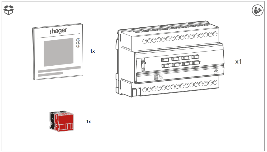
 | Scope of delivery |  | Installation by a qualified electrician |  | For further information on configuring the device, refer to the application manual |
 | KNX-certified |  | Supports KNX Data Secure | ||
 | Installation terminal with actuation opening |  | Compatibility with KNX S-mode (ETS) |  | Compatibility with Hager Easytool |
 | Suitable for use in China |  | Suitable for use in Morocco |  | Suitable for use in Australia and New Zealand |
| Symbol | Warning word | Consequence of non-observance |
 |  | Leads to serious injuries or death. |
 | Can lead to serious injuries or death. | |
 | Can lead to minor injuries. | |
| Can lead to device damage. | |
| Note | Can lead to physical damage. |
| Symbol | Description |
 | Warning against electric shock. |
 | Warning against damage from mechanical stress. |
 | Warning against damage from electricity. |
 | Warning against damage from fire. |
Target group

Electronic devices may only be assembled, installed and configured by an electrically trained and certified specialist in accordance with the relevant installation standards of the country. The accident prevention regulations valid in the appropriate countries must be complied with.
In addition, these instructions are intended for system administrators and electrically trained specialists.
Scope of delivery
Fig. 1: TYMS616D scope of delivery
Design and layout of the device
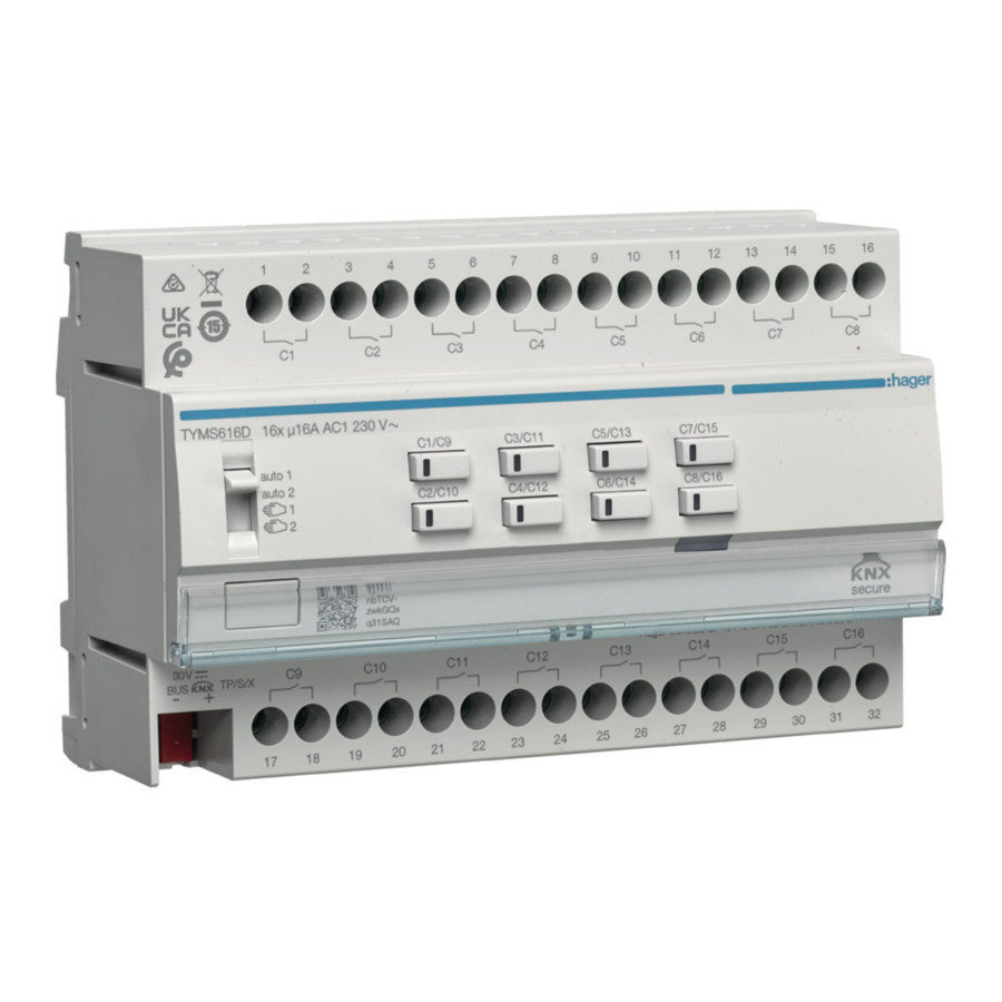
Fig. 2: Design and layout of the device, switching/blind actuator, 16/8-gang
- Slide switch auto 1/auto 2/
![]() /
/ ![]()
 /
/ 
- KNX bus connection terminal
- Connections of loads
- Labelling field
- Illuminated programming button
- Operation button for manual mode for each pair of outputs with status LED
Function
System information
This device is a product of the KNX system and corresponds to the KNX guidelines. Detailed specialised knowledge obtained from KNX training courses is required for understanding.
The device is KNX Data Secure-compatible. KNX Data Secure can be configured in the ETS project and offers protection against manipulation in building automation. Detailed knowledge on this subject is required. For KNX Secure commissioning, a device certificate (FDSK) is required, which is attached to the device (QR code label). During installation, the device certificate must be removed from the device and kept in a safe place.
The planning, installation and commissioning of the device are carried out with KNX-certified software.
systemlink commissioning
The function of the device is software-dependent. The software is to be obtained from the product database. You can find the latest version of the product database, technical descriptions as well as conversion and additional support programmes from our website.
easylink commissioning
The function of the device is configuration-dependent. The configuration can also be performed using devices developed specially for simple setting and commissioning.
This type of configuration is only possible with devices compatible with the easylink system. easylink stands for easy, visually supported commissioning. Preconfigured standard functions are assigned to the inputs/outputs by means of a service module.
Functional description
The switching/blind actuator 16/8-gang receives telegrams from sensors or other controls via the KNX and switches electrical consumers. The relay outputs of the actuator can be set in the ETS to switching operation or to blind operation (2 outputs per channel). Mixed operation of these operating modes is also possible on the device.
In switching operation, the device switches electrical loads, such as lighting; alternatively, in blind operation, it can use its outputs to control electrically operated blinds, roller shutters, awnings or similar hangings suitable for mains voltage.
The operation buttons for manual mode on the front of the device can be used to switch the outputs in KNX mode or an unprogrammed state. This provides a quick way of checking the function of the connected consumers (building site operation).
Correct use
- Switching of electrical loads (230 V AC) with potential-free contacts
- Switching of electrically operated motors (230 V AC) for blinds, shutters, awnings and similar hangings
- Installation on DIN rail according to IEC 60715
Product characteristics
- Compatible with KNX Data Secure products
- Manual activation of the outputs on the device possible, building site operation
- Status indication of the outputs on the device
- Scene function
- Forced position by higher-level controller
- Connection of various external conductors possible
Functions in switching operation:
- NO or NC operation
- Feedback function
- Central switching functions
- Time switching functions: on delay, off delay, stair light switch with pre-warning function
- Scene function
- Operating hour meter
Functions in roller shutter/blind operation:
- Suitable for AC motors 110–230 V
- Position can be started directly
- Slat position directly controllable
- Feedback of operating state, hanging position and slat adjustment
- Forced position by higher-level controller
- Safety function: 3 independent wind alarms, rain alarm, frost alarm
- Sunshade function with automatic heating and cooling
- Disable function
- Scene function
- 3 alarms
Logic properties
- Logic gate
- Converter (conversion)
- Blocking element
- Comparator – limit switch
Operation
Switching manual mode on/off
Bus voltage supply is present.
- Push switch (1) to position
![]() .
.
Manual mode is switched on; the outputs can be controlled independently of each other via the operation buttons (see Fig. 2/6):
![]() switches on the control of outputs C1.... C8 (16-gang).
switches on the control of outputs C1.... C8 (16-gang).
![]() switches on the control of outputs C9... C16 (16-gang).
switches on the control of outputs C9... C16 (16-gang).
 During manual mode, the controller is deactivated via the KNX bus.
systemlink commissioning:
Depending on the programming, manual mode is activated permanently or for a time period configured using the application software. If manual mode is disabled via the application software, no activation takes place.
Or:
- Move switch (1) to position auto 1/auto 2.
Manual operation is switched off. Control takes place solely via the KNX bus. The output assumes the position predefined by the bus controller. The switching status is displayed by the status LED of the operation button (see Fig. 2/6).
auto 1 displays the status of outputs C1... C8 (16-gang).
auto 2 displays the status of outputs C9... C16 (16-gang).
Operating outputs in manual mode
Operation takes place per output by briefly pressing the operation button repeatedly (see Tab. 2).

Risk of damage due to simultaneous pressing of the buttons for UP and DOWN if a motor is connected when the motor is in an unprogrammed state! Motors, hangings and the device may be destroyed!
- Only ever press one button in manual mode when working with unprogrammed devices.
| Condition ((6)) | Behaviour when button is pressed ((6)) Behaviour when button is pressed (()) |
| Switching operation | |
| Load is switched off. Status LED of the button is off. | Short button press: ON – the connected load is switched on. LED of the button lights up. |
| Load is switched on. Status LED of the button lights up. | Short button press: OFF – the connected load is switched off. LED of the button goes out. |
| Roller shutter/blind operation | |
| Output is in idle state. Status LED of the button is off. | Long button press: Movement operation starts. Status LED of the button lights up. |
| Output active. Status LED of the button lights up. | Short button press: Movement operation stops. LED goes out. |
Note
If the roller shutter/blind is in the final position, the button opposite must be pressed in order to move the shutter/blind.
Information for qualified electricians
Installation and electrical connection

 Electric shock when live parts are touched!
An electric shock can lead to death!
- Isolate all connection cables before working on the device and cover any live parts in the area!
 Impermissible heating if load of the device is too high!
The device and the connected cables may get damaged in the connection area!
- Do not exceed the maximum current carrying capacity!

Risk of destruction with parallel connection of several motors on one output!
Final position switches could fuse together. Motors, hangings and the device may be destroyed!
- Only connect one motor per output!
Installing the device
Note!
Observe temperature range. Provide sufficient cooling.
- Install the device on a TH 35 7.5–15 DIN rail in accordance with IEC 60715:2017 / EN 60715:2017.
Fig. 3: Installing the device on the DIN rail


Connecting the device
The device outputs (Fig. 2/3) are parameterised as switching outputs in the ETS.
The device outputs (Fig. X) are parameterised as switching outputs in the ETS.
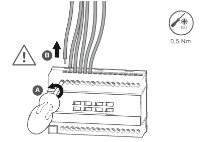
- Connect the load to the outputs of the device. In so doing, observe the torque details on the device. Two neighbouring outputs form a blind output.
Fig. 4: Connecting the connection cables

Fig. 5: Connection examples

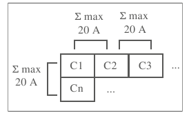
The total current carrying capacity of neighbouring outputs must not exceed 20 A.
Fig. 6: Total current carrying capacity of neighbouring outputs
![]()


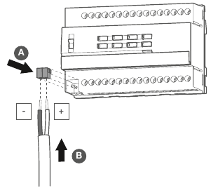
Connecting the bus cable
The connection cables for the load and power supply are connected.
- Connect the bus cable via the bus connection terminal (Fig. 2/2).
Fig. 7: Connecting the bus cable
![]()
Commissioning
The device can be programmed in three ways:
- KNX systemlink mode (standard ETS programming) see systemlink – loading the physical address and application software
- KNX Secure mode see Commissioning in KNX Secure mode
- KNX easylink mode see easylink commissioning
systemlink – loading the physical address and application software
The device has been installed and connected so that it is ready for operation.
The slide switch for manual mode (Fig. 2/1) is in position auto1/auto2.
- Switch on the bus voltage.
- Press the programming button (Fig. 2/5).
The button lights up.
![information]() If the button does not light up, no bus voltage is present on the device.
If the button does not light up, no bus voltage is present on the device. - Load the physical address into the device.
Status LED of the button goes out. - Load the application software into the device.
- Note down the physical address on the labelling field (Fig. 2/4).
- Switch on the mains voltage at the outputs.
Commissioning in KNX Secure mode
The device has been installed and connected so that it is ready for operation.
- Activate safe commissioning mode in ETS.
- Enter the device certificate (QR code) 2 (see Fig. 10), scan it (see Fig. 8) or add it to the project in ETS.
![information]() Note!
Note!
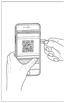
Use a high-resolution camera to scan the QR code.
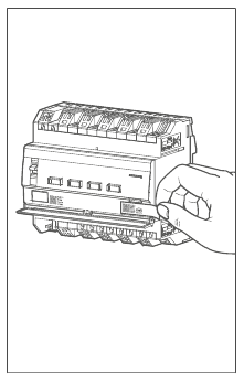
Fig. 8: Removing the device certificate from the device (similar to illustration)
![]()
Fig. 9: Scanning the QR code
![]()
Fig. 10: Entering the QR code manually
![]()

- Document all passwords and keep them in a safe place.
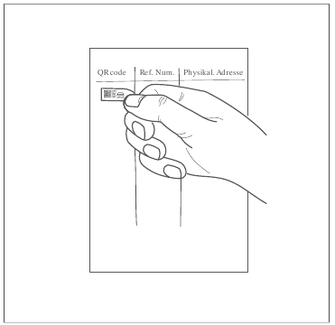
- Remove the device certificate (QR code) from the device and store it with the passwords.
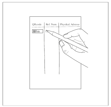
- Note down the device certificate along with the physical address and product reference.
Fig. 11: Storing the device certificate in the project documentation
![]()
Fig. 12: Noting down the article number and physical address for the device certificate
![]()
easylink
Information on the system configuration can be taken from the extensive description of the service module easylink.
Commissioning the device
The device has been installed and connected correctly.
- Switch on the mains voltage at the outputs.
- Switch on the bus voltage.
Depending on the parameterisation, the status LEDs of the operation buttons for manual mode light up.
Determine operation time and slat adjusting time
In blind/roller shutter operation, the operation time for positioning the sunshade is important. The position is calculated based on the operation time. The slat adjusting time for slat blinds, determined by the design, is part of the total operation time. The aperture angle of the slats is therefore set as the operation time between the opened and closed position.
Note!
The operation time for UP is normally longer than the operation time for DOWN and must be measured separately if necessary.
- Measure the UP and DOWN operation time of the hanging.
- Measure the slat adjusting time between OPEN and CLOSED.
- Enter the measured values into the parameter setting – running time or slat step time.
Functional test
The functionality of the outputs is displayed via the status LED of the operation button (Fig. 2/6).
 /auto 1 displays the status of the outputs C1... C8 (16-gang).
 /auto 2 displays the status of the outputs C9... C16 (16-gang).
| LED status | Meaning of the signal |
| Switch operation: | |
| LED lights up permanently. | Load is activated. |
| LED flashes. | No load connected. |
| Roller shutter/blind operation: | |
| LED flashes. | Roller shutter, blind in movement operation |
| LED lights up permanently. | Roller shutter, blind in final position |
The individual outputs can be switched in manual mode via the operation button (Fig. 2/6).
The device has been installed and connected correctly.
The mains and bus voltage are switched on.
Roller shutter/blind operation
The roller shutter/blind is in the top final position.
- Move the slide switch (Fig. 2/1) to the manual position.
- Press the manual operation button (Fig. 2/6) briefly (jog mode).
The connected roller shutter/blind gradually moves down and the status LED lights up each time the button is pressed.
OR:
- Hold down the manual operation button (Fig. 2/6) for > 2 s.
The connected roller shutter/blind moves to the bottom final position and the status LED flashes until the final position is reached.
Switching operation
The connected load is switched off.
- Move the slide switch (Fig. 2/1) to the manual position.
- Press the manual operation button (Fig. 2/6) briefly for < 2 s.
The connected load is switched on and the status LED of the button lights up.
Dismantling
Disconnecting the load cables
All the cables delivering voltage to the device are switched off.
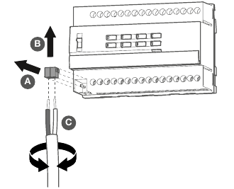
- Unscrew and remove the connection cables from the device.
Fig. 13: Disconnecting the load cables
![]()
Removing the bus connection terminal
The bus voltage is switched off.
- Remove the bus connection terminal from the device.
Fig. 14: Removing the bus connection terminal
![]()
Dismantling the device
The bus connection cable and the load cables have been disconnected.
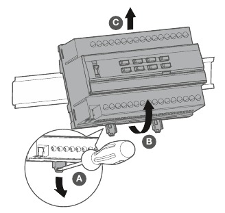
- Remove the device from the DIN rail.
Fig. 15: Removing the device from the DIN rail
![]()
Technical data

Troubleshooting
Manual operation not possible
Switch (1) not set to 
 Move switch to
Manual operation is not enabled (systemlink).
Enable manual operation via application software.
Bus operation not possible
Bus voltage is not present.
Check bus connection terminals for correct polarity.
Check bus voltage by briefly pressing the programming button (5), red LED lights up if bus voltage is present.
Manual mode is active
Switch (1) is in position
Move switch (1) to position auto1/auto2.
Roller shutters/blinds do not move to the final position.
Operation time for the roller shutters/blinds is set incorrectly.
Check operation times. Check measurements and reprogram device if necessary.
Accessories
Optional accessories
| KNX bus connection terminals, 2-pole, red/black | TG008 |
| KNX system cable, Y(ST)Y,2x2x0.8 | TG01x |
Safety instructions
Electrical devices must only be installed and assembled by a qualified electrician in accordance with the relevant installation standards, guidelines, regulations, directives, safety and accident prevention directives of the country.
Hazard due to electric shock. Disconnect before working on the device or load. Take into account all circuit breakers that supply dangerous voltages to the device or load.
Failure to comply with these installation instructions may result in damage to the device, fire or other hazards.
due to electric shock. The device is not suitable for safe disconnection or isolation of the mains supply.
due to electric shock on the SELV/PELV installation. Not suitable for switching SELV/ PELV voltages.
Connect one motor per output only. If several motors are connected, motors or device might be destroyed.
Use drives with mechanical or electrical final position switches only. Check final position switches for correct adjustment. Comply withh motor manufacturer's data. The device may get damaged.
Do not connect any three-phase motors. The device may get damaged.
Observe the motor manufacturer's data regarding change-over time and max. duty cycle.
Documents / ResourcesDownload manual
Here you can download full pdf version of manual, it may contain additional safety instructions, warranty information, FCC rules, etc.
Advertisement


Need help?
Do you have a question about the TYMS616D and is the answer not in the manual?
Questions and answers