Table of Contents
Advertisement
Quick Links
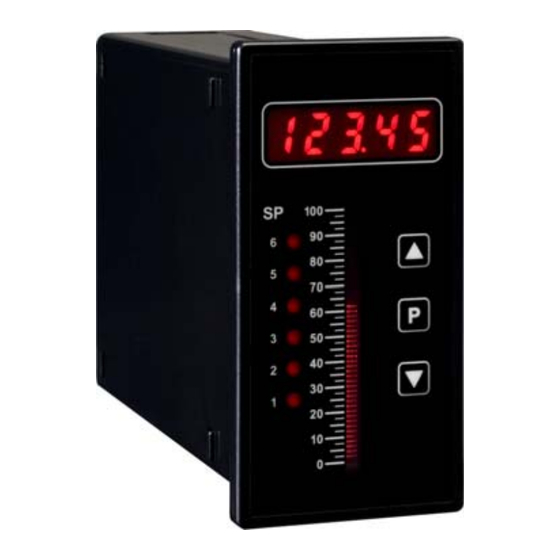
PROCESS CONTROLLER + BAR GRAPH
TEX - BAR
- R2
- R2A
- R2S
- R2AS
- R4
- R4A
- R4S
- R4AS
TEX-BAR
TEX Range 4-20mA/0-10V bar graph process controller
2 x relay outputs
2 x relay outputs, 1 x analogue output
2 x relay outputs, 1 x serial output
2 x relay outputs, 1 x analogue output, 1 x serial output
4 x relay outputs
4 x relay outputs, 1 x analogue output
4 x relay outputs, 1 x serial output
4 x relay outputs, 1 x analogue output, 1 x serial output
- HV
85-265V AC / 95-370V DC power
- LV
15-48V AC / 10-72V DC power
Advertisement
Table of Contents

Subscribe to Our Youtube Channel
Related Manuals for Define Instruments TEX-BAR

Summary of Contents for Define Instruments TEX-BAR
- Page 1 TEX-BAR PROCESS CONTROLLER + BAR GRAPH TEX - BAR TEX Range 4-20mA/0-10V bar graph process controller - R2 2 x relay outputs - R2A 2 x relay outputs, 1 x analogue output - R2S 2 x relay outputs, 1 x serial output...
-
Page 2: Table Of Contents
5 - Input Setup & Calibration ............10 6 - Setpoint Setup ................17 7 - Setpoint Open Access ............... 20 8 - Reset PIN Numbers ..............20 APPENDICES A - Serial Modes ................21 TEX-BAR-MAN-11V04 (SEP11) Copyright © 2011... -
Page 3: General Information
(4-20mA) or voltage (0-10V). Window program- mable over any range within the controller's full-scale range. Serial port Isolated RS232 or RS485 Modes: ASCII, Modbus RTU slave, Ranger A output Data rates: 300-38400 baud. Parity: Odd, even or none. Copyright © 2011 TEX-BAR-MAN-11V04 (SEP11) -
Page 4: Wiring
Remove the backing plate by inserting a screwdriver into the indents (indicated on the diagram). Then gently slide the input module from the case (see 3.1A to identify the input module). TEX-BAR-MAN-11V04 (SEP11) Copyright © 2011... - Page 5 + 24V EXC SENSOR Loop powered sensor - NEG N / C + POS + Signal 3-wire current/voltage input + 24V EXC + Supply Controller supplied excitation I /V - NEG - Signal / - Supply Copyright © 2011 TEX-BAR-MAN-11V04 (SEP11)
- Page 6 Serial port (if fitted) (see 3.1E) If your controller has a RS232 RS485 (RJ11) serial port fitted, wire it (Screw terminal) as shown. +5V DC (option) If there is no serial port fitted, skip this step. TEX-BAR-MAN-11V04 (SEP11) Copyright © 2011...
- Page 7 (LV) CONTROLLER TO -DC / neutral AC MAINS POWER. Once you have completed the wiring process it is safe to switch on your power supply. Ensure that your display is functioning before you proceed. Copyright © 2011 TEX-BAR-MAN-11V04 (SEP11)
-
Page 8: Casing & Display
CASING & DISPLAY CASING & DISPLAY Case dimensions Dimensions 96 x 48 x 119.5mm (H x W x D) Panel cutout 92.5mm x 45.5 (H x W) 96.0 48.0mm 48.0 119.5 mm TEX-BAR-MAN-11V04 (SEP11) Copyright © 2011... - Page 9 To adjust the display brightness, press the buttons together from the main display. BRI appears and toggles with the current setting. Use the buttons to adjust the LED backlight, and then press to return to the normal operating mode. Copyright © 2011 TEX-BAR-MAN-11V04 (SEP11)
-
Page 10: Input Setup & Calibration
(0-20mA), 2V (0-2V) or 10V (0-10V). Then press If you opt to change the input mode in this section then the header plug on the input module may also need to be changed. See 3.2 for more information. TEX-BAR-MAN-11V04 (SEP11) Copyright © 2011... - Page 11 S.G. value set to 1.0. What did you select in 5.3A? SKIP Proceed to 5.4 AUTO Complete steps 5.3C-E Complete steps 5.3F-H S.G. Complete step 5.3I Copyright © 2011 TEX-BAR-MAN-11V04 (SEP11)
- Page 12 The text string for [LOW] will differ depending on your input range (selected in 5.2C): 0MA (for 0-20mA), 4MA (for 4-20mA) or 0V (for 0-2V/0-10V). _ _ _ ENTER DISPLAY VALUE FOR [HIGH] scrolls across the display, and the currently selected high display value appears. Use the buttons to set TEX-BAR-MAN-11V04 (SEP11) Copyright © 2011...
- Page 13 Using the buttons, alter the number of input samples that the controller will average, and then press Increasing the number of samples will stabilise measurement, but it will also slow down response rates. Copyright © 2011 TEX-BAR-MAN-11V04 (SEP11)
- Page 14 ? scrolls across and toggles with SKIP. Press now to skip analogue output calibration, or the button and then to ENTER. What did you select in 5.5D? SKIP Skip to step 5.6A ENTER Continue to 5.5F TEX-BAR-MAN-11V04 (SEP11) Copyright © 2011...
- Page 15 300, 600, 1200, 2400, 4800, 9600, 19200 or 38400. Then press _ _ _ PARITY scrolls across the display and toggles with the currently selected parity. Using the buttons, select: NONE, ODD or EVEN. Press Copyright © 2011 TEX-BAR-MAN-11V04 (SEP11)
- Page 16 _ _ _ ENTER NEW CAL PIN NUMBER scrolls across the display and toggles with the current PIN (default 1). Using the buttons, enter your new calibration PIN number. Then press to exit to the operational display. TEX-BAR-MAN-11V04 (SEP11) Copyright © 2011...
-
Page 17: Setpoint Setup
ABOVE or BELW (below) the setpoint value, and then press ABOVE: Relay turns on above the setpoint value and off below it. BELW: Relay turns on below the setpoint value and off above it. Copyright © 2011 TEX-BAR-MAN-11V04 (SEP11) - Page 18 Choosing YES will allow the selected setpoint to be quick-edited via the button without entering a PIN (see section 7). Open access can be independently configured for each setpoint. What did you select in 6.2A? SP 1 Skip to step 6.2J Other Continue to step 6.2I TEX-BAR-MAN-11V04 (SEP11) Copyright © 2011...
- Page 19 _ _ _ ENTER NEW SP PIN NUMBER scrolls across the display and toggles with the current PIN (default 1). Using the buttons, enter your new setpoint entry PIN number. Then press to exit to the operational display. Copyright © 2011 TEX-BAR-MAN-11V04 (SEP11)
-
Page 20: Setpoint Open Access
_ _ _ ALL PIN NUMBERS RESET TO 1. Reset the default PIN numbers if required by following the instructions in 5.8 (for input setup and calibration) and 6.3 (for setpoint setup), entering ‘1’ whenever you are prompted for your current PIN. TEX-BAR-MAN-11V04 (SEP11) Copyright © 2011... -
Page 21: A - Serial Modes
SEPARATOR CHARACTER - The separator character can be either a space or a comma, and is used to separate the register address from the data value. Copyright © 2011 TEX-BAR-MAN-11V04 (SEP11) - Page 22 Setpoint 6 Make delay SP2 D/A scale low value Make delay SP3 D/A scale high value Make delay SP4 Make delay SP5 NB: Setpoint registers only active for Make delay SP6 models with relay outputs installed. TEX-BAR-MAN-11V04 (SEP11) Copyright © 2011...
- Page 23 40587 (40588) D/A scale low value 40073 Make delay SP3 40591 (40592) D/A scale high value 40074 Make delay SP4 40075 Make delay SP5 NB: Setpoint registers only active for 40076 Make delay SP6 models with relay output installed. Copyright © 2011 TEX-BAR-MAN-11V04 (SEP11)
- Page 24 (If there is no decimal point, then the first character is a space. Leading zero blanking applies.) STATUS - Single character output value status. 'U'=Under, '0'=Over, 'E'=Error. END - ETX character (ASCII 03) TEX-BAR-MAN-11V04 (SEP11) Copyright © 2011...
- Page 25 NOTES Copyright © 2011 TEX-BAR-MAN-11V04 (SEP11)
- Page 26 NOTES TEX-BAR-MAN-11V04 (SEP11) Copyright © 2011...
- Page 27 NOTES Copyright © 2011 TEX-BAR-MAN-11V04 (SEP11)
- Page 28 Copyright © 2011 Define Instruments 10B Vega Place, Mairangi Bay North Shore City 0632, New Zealand +64 (9) 835-1550 Aus: 1800 810-820 TEX - BAR Fax: +64 (9) 835-1250 DOCUMENT REVISION CODE: TEX-BAR-MAN-11V04 www.defineinstruments.com...
Need help?
Do you have a question about the TEX-BAR and is the answer not in the manual?
Questions and answers