Chapters
Table of Contents

Related Manuals for Afag LTM-H


Summary of Contents for Afag LTM-H
- Page 1 Assembly & Operating Instructions Linear-Transport-Module LTM-H Translation of the Original Assembly Instructions EN LTM-H Order no.: 50xxxxxx Assembly instructions DE LTM-H Date 01.06.2021 Version 1.0 1-56 ...
- Page 2 Your Afag team © Subject to modifications The linear transport modules from Afag Automation AG have been built according to the state-of-the-art. Due to the constant technical development and improvement of our products, we reserve the right to make technical changes at any time.
-
Page 3: Table Of Contents
Safety signs on the LTM or the working environment ........ 17 Warning signs ..................17 Mandatory signs ................... 17 Technical data ...................... 18 LTM-H ......................18 Workpiece carrier load................19 Transport, packaging and storage ..............20 General ....................... 20 Safety instructions for transport ..............20 Scope of delivery and accessories ............. - Page 4 Measures to be taken after maintenance work .......... 48 Repair work ....................48 spare and wear parts lists ................48 Toothed belt ..................49 Guides ....................50 4 – 56 Assembly instructions EN LTM-H Date 01.06.2021 Version 1.0 ...
- Page 5 Decommissioning, disassembly, disposal ............51 10.1 Safety instructions for decommissioning, dismantling and disposal ..51 10.2 Decommissioning ..................51 10.3 Disassembly ....................51 10.4 Disposal ...................... 52 Declaration of incorporation ................53 Assembly instructions DE LTM-H Date 01.06.2021 Version 1.0 5-56 ...
-
Page 6: General
NOTICE This safety note points out a potentially dangerous situation which, if not avoided, can cause substantial damage to property and the environment. 6 – 56 Assembly instructions EN LTM-H Date 01.06.2021 Version 1.0 ... - Page 7 Warning - Magnetic field Warning - back injury due to heavy lifting. Warning - Risk of injury as a result of parts being flung out! Warning -high noise levels Assembly instructions DE LTM-H Date 01.06.2021 Version 1.0 7-56 ...
-
Page 8: Additional Symbols
Wear parts (e.g. shock absorbers) are excluded from the warranty.* The warranty covers the replacement or repair of defective Afag parts. Further claims are excluded. However, a customer has a right to a defect-free product. This does also apply to defective accessories and wear parts. -
Page 9: Liability
No changes shall be made to the LTM unless described in this instruction manual or approved in writing by Afag Automation AG. Afag Automation AG accepts no liability for unauthorized changes or improper assembly, installation, commissioning, operation, maintenance or repair work. -
Page 10: Safety Instructions
Tilting the LTM-H to one side during transport or operation. Restrict the intended mobility of the workpiece carriers. Integration of the LTM-H on sloping surfaces or use as a lifting device. The coupling of the workpiece carriers with each other. -
Page 11: Obligations Of The Operator And The Personnel
The operating company shall be solely responsible for such damage, and Afag Automation AG does not accept any liability for damages caused by improper use. 2.4 Obligations of the operator and the personnel... -
Page 12: Obligations Of The Personnel
Authorized persons who due to their specialized professional training, expertise and experience are capable of identifying risks and preventing possible hazards arising from the use of the machine. 12 – 56 Assembly instructions EN LTM-H Date 01.06.2021 Version 1.0 ... -
Page 13: Personal Protective Equipment (Ppe)
Hearing protectors are required to protect the personnel against excessive noise levels to prevent noise-induced hearing loss. Assembly instructions DE LTM-H Date 01.06.2021 Version 1.0 13-56 ... -
Page 14: Safety And Protection Equipment
No changes may be made to the LTM which have not been described in these assembly instructions or approved in writing by Afag Automation AG. Afag Automation AG accepts no liability for unauthorised changes or improper assembly, installation, commissioning, maintenance or repair work. -
Page 15: General Hazards / Residual Risks
The operating company is responsible for ensuring that the permissible noise levels are observed. If the noise level exceeds 85 dB(A) in normal operation, the operator must wear hearing protectors at the workplace. Assembly instructions DE LTM-H Date 01.06.2021 Version 1.0 15-56 ... -
Page 16: Danger Due To High Temperatures
The due diligence obligations of the operating company include ensuring that the personnel carrying out maintenance work is appropriately trained and qualified. 16 – 56 Assembly instructions EN LTM-H Date 01.06.2021 Version 1.0 ... -
Page 17: Dangers Due To Incorrect Fastening
WARNING Danger if the LTM is not correctly fastened! The LTM-H can be firmly screwed to a substructure through the base plate. If the LTM-H is operated without a suitable screw connection, the LTM can move and fall during operation. -
Page 18: Technical Data
Technical data Technical data 3.1 LTM-H LTM-H Speed up to 200 cycles/min Repeatability up to +/- 0.05 mm Feed lengths 10, 20, 30, 40, 60, 80, 90, 120, 180, 240 mm or continuous operation Feed time from 0.1 sec. depending on feed length and workpiece carrier load... -
Page 19: Workpiece Carrier Load
Each workpiece carrier is designed for a payload of approx. 1000 [g]. Depending on customer requirements, the load capacity of the workpiece carriers can be increased after consultation with Afag. If you have any questions about changing the payload, please contact our customer service. -
Page 20: Transport, Packaging And Storage
Only lift the LTM with a suitable lifting device (crane, forklift). Also observe the safety instructions in chap. 2 „Safety instructions“ in this manual. 20 – 56 Assembly instructions EN LTM-H Date 01.06.2021 Version 1.0 ... -
Page 21: Scope Of Delivery And Accessories
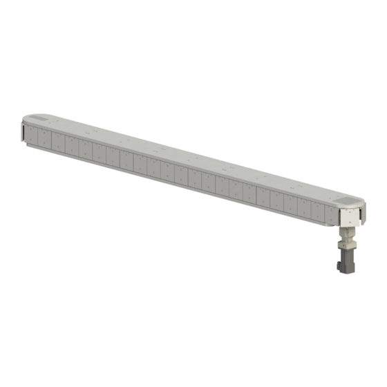
4.3 Scope of delivery and accessories The standard scope of delivery consists of the following components: Linear transport module (Fig. 1, 1) Drive system (Fig. 1, 2) AFAG standard Fig. 1 Accessories for linear transport module Pos. 2: AFAG standard drive system consisting of:... -
Page 22: Transport
4.4 Transport WARNING Danger due to improper use of lifting devices! There is a risk of danger if lifting devices are used improperly and the LTM-H is not fastened properly. Use suitable equipment with sufficient lifting capacity (e.g. crane, forklift). -
Page 23: Packaging
Store the LTM on a level, even and solid ground (secure against tipping). Clean the LTM and protect the blank metal parts against corrosion using the appropriate means. Cover the LTM completely and protect against dirt and dust. Assembly instructions DE LTM-H Date 01.06.2021 Version 1.0 23-56 ... -
Page 24: Structure And Description
5.1 Structure of the linear transport module Fig. 3 Linear transport module (exemplary illustration) Base plate Deflector module Middle module Drive module Workpiece carrier Motor Planetary gear Attachment kit Maintenance opening 24 – 56 Assembly instructions EN LTM-H Date 01.06.2021 Version 1.0 ... -
Page 25: Product Description
7. Deflection pulley 2. Middle module 8. Attachment kit 3. Deflector module 9. Gear 4. Workpiece carrier 10. Motor 5. Drive unit 11. Clamping device 6. Toothed belt Assembly instructions DE LTM-H Date 01.06.2021 Version 1.0 25-56 ... -
Page 26: Fields Of Application
Integration into an assembly system where high cycle rates are required As stand-alone machine for high output For use in the food industry (after consultation with Afag) Fig. 5 Example of application linear transport module on assembly line 26 –... -
Page 27: Installation, Assembly & Setting
The installation position of the LTM is horizontal. The LTM-H is intended for use in closed dry rooms in an industrial environment. The LTM-H is part of a machine and is not designed for use in aggressive ambient media. -
Page 28: Views Of The Ltm (General View And Engine/Gearbox Installation)
9. Motor 5. Workpiece carriers Assembly kit consisting of: gear adapter and clamping set Multi-stage planetary gear unit Servo motor Fig. 7 Overview motor and gearbox installation 28 – 56 Assembly instructions EN LTM-H Date 01.06.2021 Version 1.0 ... -
Page 29: Attachment And Tightening Torque
Galvanized blue, oiled or greased Value Tightening torques 2.6 – 3.3 Nm 5.2 – 6.5 Nm 9.0 – 11.3 Nm 21.6 – 27.3 Nm 43.0 – 54.0 Nm Assembly instructions DE LTM-H Date 01.06.2021 Version 1.0 29-56 ... -
Page 30: Integration Of The Linear Transport Module
Switch the control unit off before starting work and lock to prevent access by unauthorized personnel. Only connect or disconnect the cables when the control is switched off. 30 – 56 Assembly instructions EN LTM-H Date 01.06.2021 Version 1.0 ... -
Page 31: Integration Of The Ltm Into An Assembly System
Switch the control unit off before starting work and lock to prevent access by unauthorized personnel. Only connect or disconnect the cables when the control is switched off. Assembly instructions DE LTM-H Date 01.06.2021 Version 1.0 31-56 ... -
Page 32: Gearbox Change And Motor Attachment
Turn the screws back into the clamping threads. Remove the 4 screws (Fig. 10, 2). Remove the gear adapter including gear and motor. The gear/motor is disassembled 32 – 56 Assembly instructions EN LTM-H Date 01.06.2021 Version 1.0 ... -
Page 33: Assembly Of The Gear / Motor
Fasten the gear adapter with the 4 x screws only so far that the adapter rests firmly on the mounting surface (do not tighten yet!). LTM-H 4 x M8 Tighten the clamping set in the following order: - Tighten the clamping screws crosswise with 1/3 TA (Fig. 11) - Tighten the clamping screws crosswise with 2/3 TA (Fig. -
Page 34: Attachment Of External Drives
6.6 Attachment of external drives The linear transport module can be fitted with a drive concept other than that offered by Afag Automation. For this purpose, the following prerequisites must be met: The diameter of the gear drive shaft must be 40 mm. This value is based on the size of the appropriate attachment set. -
Page 35: Motor Control
Thermo switches Thermo switches Fig. 13 Electrical interfaces If you are using a third-party controller or an Afag SE-Power servo controller, please read the accompanying documentation. We recommend the use of the Afag standard cables listed in the accessories list. -
Page 36: Setting And Retrofitting
Adjustment and conversion work may only be carried out by qualified personnel! Also observe the safety instructions in chap. 2 „Safety instructions“ in this manual. 36 – 56 Assembly instructions EN LTM-H Date 01.06.2021 Version 1.0 ... -
Page 37: Toothed Belt Tension
Tension the toothed belt with the tensioning screw (Fig. 15, 1), observing the adjustment dimension. Perform the operation on both sides of the LTM. The tension of the toothed belt is adjusted. Assembly instructions DE LTM-H Date 01.06.2021 Version 1.0 37-56 ... -
Page 38: Changing The Workpiece Carrier
The measurement was carried with an optical instrument pointing the crosshairs at the workpiece carriers. Setting and measuring of the LTM was carried out with the Afag standard drive. The measuring curve shows the deviation from the target position in running direction, measured optically on the crosshairs on the workpiece carrier. -
Page 39: Commissioning
Take suitable protective measures to ensure that during operation there are no persons or tools in the danger zone (workpiece carrier/deflection). Risk of injury from deflection modules and drive modules Fig. 18 Deflection and drive modules Assembly instructions DE LTM-H Date 01.06.2021 Version 1.0 39-56 ... -
Page 40: Commissioning Procedure
The rotating shaft on the drive module can cause serious injuries to the hand or fingers, especially if the cover is removed! Do not operate LTM-H without protective cover. The operator must take the necessary protective measures to adequately reduce this risk. -
Page 41: Programming
LTM. When using the Afag SE-Power servo-controller, please refer to the enclosed quick installation guide. You will also find the quick installation guide on the Internet at www.afag.com. CAUTION Risk of injury due to flying parts ejected from the LTM! There is a risk of injury from flying parts ejected from the LTM, if incorrect acceleration and deceleration values are entered into the PLC. -
Page 42: Fault Elimination
5. Do not put the LTM back into operation until the fault has been eliminated. 6. After the fault, check whether the LTM is still functional and whether there are any other hazards. 42 – 56 Assembly instructions EN LTM-H Date 01.06.2021 Version 1.0 ... -
Page 43: Tables Fault Causes And Remedy
Check correct functioning as described in chapter “7Commissioning”. Motor disconnection Check motor cable Drive defective Have the drive replaced by an Afag AG service technician Assembly instructions DE LTM-H Date 01.06.2021 Version 1.0 43-56 ... - Page 44 Marked play in the side guides Have Afag AG service technicians Excessive play replace the guides Ball bearing of drive shaft or Have ball bearings replaced by Afag Ball bearing deflection rollers defective AG service technicians Gearbox is defective ...
-
Page 45: Maintenance And Repair
In this chapter you will find a description of the maintenance work necessary to ensure an optimum and trouble-free operation of the LTM. In principle, the LTM-H is maintenance-free or requires low-maintenance for several years. Depending on the load, cycle time and cleanliness requirements, cleaning intervals can be defined. -
Page 46: Maintenance Activities And Maintenance Intervals
The intervals refer to a normal operating environment. If the LTM is to be operated in an environment with abrasive dusts or corrosive or aggressive vapours, gases or liquids, the approval of Afag Automation AG must be obtained in advance. -
Page 47: Overview Maintenance Plan
Check LTM for excessive noise levels, if necessary, determine cause and eliminate Safety signs (warning Check Monthly [Off] symbols) Check the safety label for good legibility and possible damage, replace if necessary Assembly instructions DE LTM-H Date 01.06.2021 Version 1.0 47-56 ... -
Page 48: Further Maintenance
Afag Automation AG offers a reliable repair service. We recommend that you have any repairs carried out by Afag Ag service technicians. Please note that Afag does not assume any warranty for LTM that have not been replaced or repaired by Afag! 9.6 spare and wear parts lists... -
Page 49: Toothed Belt
Tensioning of the toothed belt is not necessary. After a short running-in phase a constant belt tension is guaranteed. The toothed belts are not covered by the Afag Automation AG warranty! CAUTION Danger of injury! Risk of injury from improperly performed work when replacing the timing belt. -
Page 50: Guides
CAUTION Danger of injury! Risk of injury from improperly performed work when replacing the guides. The guides may only be replaced by trained Afag Automation AG personnel! Ordering the guides: When ordering the guides, please specify the LTM type for which the spare parts are intended. -
Page 51: Decommissioning, Disassembly, Disposal
The linear transport modules may only be removed from a system when the control is switched off and secured with a lockout device. Before disassembly unplug the cables of the motor! Assembly instructions DE LTM-H Date 01.06.2021 Version 1.0 51-56 ... -
Page 52: Disposal
Electronic parts, electrical scrap, auxiliary and operating materials must be disposed of by approved specialist companies. Information on proper disposal can be obtained from the responsible local authorities. 52 – 56 Assembly instructions EN LTM-H Date 01.06.2021 Version 1.0 ... -
Page 53: Declaration Of Incorporation
The relevant technical documentation was created according to Annex VII, Part B of the above-mentioned Directive. Authorised representative for compiling the technical documentation: Niklaus Röthlisberger, Product Manager, Afag Automation AG, CH-6144 Zell Place/Date: Zell, 01.06.2021 Siegfried Egli Niklaus Röthlisberger... - Page 54 Obligations of the operating company ....11 Obligations of the personnel ......12 Technical data ........... 28 Operation ............42 Operator ............. 12 Warning against hot surfaces ......17 54 – 56 Assembly instructions EN LTM-H Date 01.06.2021 Version 1.0 ...
- Page 55 Fig. 18 Deflection and drive modules ......................39 Fig. 19 LTM maintenance points ......................... 47 Fig. 20 Installation position (1) of the toothed belt (exemplary illustration) ..........49 Assembly instructions DE LTM-H Date 01.06.2021 Version 1.0 55-56 ...
- Page 56 List of figures 56 – 56 Assembly instructions EN LTM-H Date 01.06.2021 Version 1.0 ...
Need help?
Do you have a question about the LTM-H and is the answer not in the manual?
Questions and answers