Chapters
Table of Contents

Related Manuals for Gotting HG G-98870-A


Summary of Contents for Gotting HG G-98870-A
- Page 1 Transponder 1D Transponder Antenna with Continuous Localization HG G-98870-A CAN/CANopen® or PROFINET® interface English, Revision 01 Date: 25.06.2024 Dev. by: GB Author(s): RAD / GB Innovation through Guidance www.goetting-agv.com...
- Page 2 Configuration via Ethernet with web browser (Google Chrome, Opera, Firefox, Edge and others) © 2024 Götting KG, errors and modifications reserved. The Götting KG in D-31275 Lehrte has a certified quality management system according to ISO 9001. Device Description HG G-98870-A | English, Revision 01 | Date: 25.06.2024...
-
Page 3: Table Of Contents
Minimum Distance Between Antenna and Transponder..........27 7.3.3 Minimum Distance between Transponder Antennas ............28 7.3.4 Minimum Distance to Current-Carrying Wires Around the Transponder Antenna and Metal-Free Areas..................... 28 7.3.5 Connection Example .........................29 Device Description HG G-98870-A | English, Revision 01 | Date: 25.06.2024... - Page 4 Tune Transmitter Coil .........................60 10.2.8.2 Detected Threshold........................61 10.2.8.3 Mounting Configuration......................62 10.2.9 Configuration – CAN Bus .......................63 10.2.10 Configuration – Network .........................66 10.2.11 Configuration – Logging ........................66 10.2.12 Configuration – Security ........................67 Device Description HG G-98870-A | English, Revision 01 | Date: 25.06.2024...
- Page 5 Transmit PDO_4 Mapping Parameter 3 (Other)..............106 20.2.17 8-bit Digital Input (Transmission in TPDO_1 and TPDO_4) ......... 107 20.2.18 16-bit Digital Input (Transmission in TPDO_1 and TPDO_4) ........107 Device Description HG G-98870-A | English, Revision 01 | Date: 25.06.2024...
- Page 6 List of Tables..................... 115 Index......................118 Revision History..................121 Copyright and Terms of Liability............122 25.1 Copyright..............................122 25.2 Exclusion of Liability ..........................122 25.3 Trade Marks and Company Names ....................122 Device Description HG G-98870-A | English, Revision 01 | Date: 25.06.2024...
-
Page 7: About This Document
Glass transponder HG G-70633 http://www.goetting.agv.com/components/70633 – Puck transponder HG G-70652 http://www.goetting.agv.com/components/70652 – Puck transponder HG G-70653 http://www.goetting.agv.com/components/70653 – Marking nail transponder HG G-70654 http://www.goetting.agv.com/components/70654 – Transponder programmer HG G-81840 http://www.goetting.agv.com/components/81840 Device Description HG G-98870-A | English, Revision 01 | Date: 25.06.2024... -
Page 8: Presentation Of Information
1.2.2 Symbols In this device description the following symbols and formatting are used: If this information is ignored the product may not be operated in an optimal way. Device Description HG G-98870-A | English, Revision 01 | Date: 25.06.2024... -
Page 9: Variants Of The Transponder Antenna
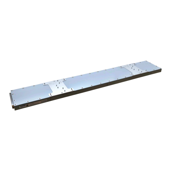
The closed side is the reading side, which must face the transponders. When mounted under an AGV, it faces the ground. Reading and mounting side of the transponder antenna Figure 1 Mounting side Reading side (opposite the mounting side) Device Description HG G-98870-A | English, Revision 01 | Date: 25.06.2024... -
Page 10: Coordinate System Of The Transponder Antenna
Chapter 1 – About this Document 1.4.2 Coordinate System of the Transponder Antenna The transponder antenna HG G-98870-A is a one-dimensional antenna. The coordi- nate system shown in the following image shows the relative coordinate system of the antenna. The antenna can be moved forwards and backwards in the X direction. However, it expects the transponder positions to be in ascending order in the +X direction. -
Page 11: Abbreviations
Controller Area Network open Process Data Object Programmable logic controller or PC that performs control functions PROFINET® Process Field Network RAGV Rail-guided AGV Rail Mounted Gantry RFID Radio-Frequency Identification Service Data Object Device Description HG G-98870-A | English, Revision 01 | Date: 25.06.2024... -
Page 12: Safety Information
Position detection of a rail-guided automated guided vehicle (RAGV). The HG G-98870-A transponder antenna is used to detect the position of rail-guided automated guided vehicles (RAGVs), such as RMGs in container terminals. The transponder antenna HG G-98870-A may only be used by qualified personnel at the place of use (e.g. -
Page 13: Qualification Of The Users
2.4 General Safety Information Ensure that the transponder antenna HG G-98870-A is only used in applications – in which sufficient measures have been implemented for personal protec- tion and the safe detection of obstacles, –... -
Page 14: Obligations Of The Operator
The operator must not modify or alter the transponder antenna without authoriza- tion. Otherwise, the operating permit will become invalid. Device Description HG G-98870-A | English, Revision 01 | Date: 25.06.2024... -
Page 15: Scope Of Delivery
Ethernet (Ser- Available as an accessory from other suppliers: Cable, approx. vice) 2 m, RJ45 plug to M12 plug, D-coded, shielded HG G-70633ZB Glass transponder usually mounted in the ground Device Description HG G-98870-A | English, Revision 01 | Date: 25.06.2024... -
Page 16: Optional Accessories
Order No., Description HG Z-98870-001 Mounting bracket set (includes 2x mounting brackets, s. section 7.3.7 on page 31) HG G-81840ZA Transponder programming device for reading and programming transponder codes Device Description HG G-98870-A | English, Revision 01 | Date: 25.06.2024... -
Page 17: Device Overview
Transponders with trovan® coding are used as reference marks for the track guid- ance (see section 3.1 on page 15). Further documents can be obtained from our In- ternet server (see section 1.1.2 on page 7). Device Description HG G-98870-A | English, Revision 01 | Date: 25.06.2024... -
Page 18: Structure Of The Transponder Code
Chapter 4 – Device Overview 4.2.2 Structure of the Transponder Code The antenna HG G-98870-A evaluates 20 useful bits. The transmission time for a complete code telegram is 8 ms. 4.2.3 Reading Distances of the Transponders The range of the transponders differs. The following table shows the achievable reading distances of the transponder types recommended in Table 4 on page 15. -
Page 19: Displays (Leds)
Flashes when waiting for synchroniza- tion. – Flashes if there is a connection but no communication to the PROFINET® con- troller. – Lights up when there is no connection Device Description HG G-98870-A | English, Revision 01 | Date: 25.06.2024... -
Page 20: Busy Mode
Once the functions that require busy mode have been completed, the antenna au- tomatically switches back to normal operation. In this device description, it is indicated when functions trigger busy mode. Device Description HG G-98870-A | English, Revision 01 | Date: 25.06.2024... -
Page 21: Operating Principle
Fur- thermore, there are other systems for transmitting and decoding the code which are not described in this operating manual. Device Description HG G-98870-A | English, Revision 01 | Date: 25.06.2024... -
Page 22: Track Guidance With Transponders
However, the transponders must not be positioned too close together, otherwise reading errors will occur (s. section 7.1.1 on page 24) Also, no more than two tran- sponders may be in the antenna field at the same time. Device Description HG G-98870-A | English, Revision 01 | Date: 25.06.2024... -
Page 23: Storage
Store the device in closed rooms only. Make sure that the storage room is sufficiently ventilated and dry. Protect the device from damage caused by dirt, dust or moisture. Device Description HG G-98870-A | English, Revision 01 | Date: 25.06.2024... -
Page 24: Mounting
Observe the minimum distances specified in the associated data sheets (see section 1.1.2 on page 7). A minimum distance of 1000 mm is required between two transponders. Device Description HG G-98870-A | English, Revision 01 | Date: 25.06.2024... -
Page 25: Preparation Of Connection Cables
Never connect voltage to pin 3 or 4. Pin allocation POWER (M12, 5 pin, A coded) Table 10 POWER Signal Comment Voltage supply Ground Ground Data and Supply male Device Description HG G-98870-A | English, Revision 01 | Date: 25.06.2024... -
Page 26: All Variants: Connecting Ethernet
These terminators can be obtained from various manufacturers and are available in versions for many sockets and connectors. Terminators for the CAN1 and CAN2 connectors are also offered by Götting (see 3.1 „Required Accessories“ auf Seite 15). Device Description HG G-98870-A | English, Revision 01 | Date: 25.06.2024... -
Page 27: Variant Hg G-98870Ya: Connecting Profinet
7.3 Mounting the Transponder Antenne 7.3.1 Operating Conditions of the Antenna The transponder antenna HG G-98870-A is approved for indoor and outdoor use. It may be used in a temperature range from -20° C bis +50° C. The relative humidity at 25° C may be max. 95 % (without condensation). -
Page 28: Minimum Distance Between Transponder Antennas
Two or more transponder antennas operating at the frequencies 128/64 kHz must maintain a minimum distance from each other in order not to interfere with each other. The minimum distance between two HG G-98870-A transponder antennas is 2000 mm. As a matter of principle, larger transponder antennas must maintain a greater dis- tance. -
Page 29: Connection Example
Terminating resistor (optional) Configuration / Logging – Emergency update Mounting bracket (optionally availabe as an accessory) Transponder antenna Reading distance Transponder (depending on theTransponder type on or in the ground) Ground Device Description HG G-98870-A | English, Revision 01 | Date: 25.06.2024... -
Page 30: Mounting / Attaching The Antenna To The Vehicle
Mounting brackets must not protrude beyond the mounting plates. Do not open or use the screws with which the mounting plates are attached to the antenna housing, otherwise the antenna may become unsealed. Device Description HG G-98870-A | English, Revision 01 | Date: 25.06.2024... -
Page 31: Mounting With The Optionally Available Mounting Kit Hg Z-98870-001
Mounting – Chapter 7 Dimensions of the transponder antenna HG G-98870-A, pictured with the optional Figure 12 mounting brackets 1161 Max. Range for mounting profile Mounting side 2118 2x mounting bracket (optional accessory) Reading side (Underside) 1500 Base plate always mounted on the antenna body Reading area 7.3.7 Mounting with the Optionally Available Mounting Kit HG Z-98870-001... -
Page 32: Figure 14 Mounting The Optional Mounting Kit
M8 bolts on the mounting plate. Use self- locking M8 A4 stainless steel nuts again. Then use M8x16 cylinder head screws to fasten the support corners to the angle plate. Device Description HG G-98870-A | English, Revision 01 | Date: 25.06.2024... -
Page 33: Commissioning
Commissioning WARNING Danger due to lack of safety measures The transponder antenna HG G-98870-A does not contain any safety devices. Only use the antenna in applications where sufficient measures have been implemented for personal protection and safe detection of obstacles. -
Page 34: Adjust Ethernet Settings
The subnet mask must match the subnet mask of the antenna. If the antenna uses the default setting (see above), then Example: Ethernet settings of the computer Figure 16 Device Description HG G-98870-A | English, Revision 01 | Date: 25.06.2024... -
Page 35: Configuring The Antenna Via The Configuration Web
The Ethernet LED of the antenna starts flashing because data is being transmit- ted. The following antenna menu opens in the web browser. Basic menu of the antenna after successfully calling up the web pages Figure 17 Device Description HG G-98870-A | English, Revision 01 | Date: 25.06.2024... -
Page 36: Set Parameters
If interference and transponder signal overlap, the transponder signal will still be distorted. It is therefore strongly recommended to eliminate inter- ferences and to establish a high signal-to-noise ratio, see also section 18.2 on page Device Description HG G-98870-A | English, Revision 01 | Date: 25.06.2024... -
Page 37: Completing Commissioning
The transponder antenna is now properly commissioned. If you need a reference file of the antenna parameters for later settings: Archive the file (see section 10.2.14 on page 70). Device Description HG G-98870-A | English, Revision 01 | Date: 25.06.2024... -
Page 38: Interfaces
Optionally, the connection box M12-5-8-USB HG G-20960 can be connected between the device and PC. This allows the antenna to be connected via standard M12 cables. Further information on the connection box can be found at http://goetting-agv.com/components/20960 Device Description HG G-98870-A | English, Revision 01 | Date: 25.06.2024... -
Page 39: Can Bus
CAN identifier 9.2.2 Operating Modes and States CANopen®: Parameter PDO operating mode Table 15 synchro- asynchro- only on request Value cyclic acyclic nous nous (RTR) 1-240 241-251 reserved Device Description HG G-98870-A | English, Revision 01 | Date: 25.06.2024... -
Page 40: Can
The CAN Tx ID can be set via the web configuration pages. The value can be set from 0 to 2047 (or 0 to 7FF Device Description HG G-98870-A | English, Revision 01 | Date: 25.06.2024... -
Page 41: Table 19 Structure Of The Can Message Object - Main Telegram
The first transponder is expected or read (see also section 17.2 on page 87). 0x0200 TRANSP_IM_FIELD Transponder in the field 0x0400 ABS_POS_OK Absolute position is fine. 0x0800 Reserve – 0x1000 Reserve – Device Description HG G-98870-A | English, Revision 01 | Date: 25.06.2024... -
Page 42: Can Message Object - Additional Telegrams
Meaning 1, 2 2 Byte unsigned int_16 Transponder 2 level 3,4,5,6 4 Byte unsigned int_32 Transponder 2 code 2 Byte signed int_16 Transponder 2 relative position Low Byte First Device Description HG G-98870-A | English, Revision 01 | Date: 25.06.2024... -
Page 43: Additional Telegram Other Data
(value is not saved) 0x04 RX_MASK_AUTO_TUNE Activates the Dynamic Auto-Tune function. (value is not saved) see section 9.6 on page 48 0x08 RESERVE Reserved 0x10 RESERVE Reserved 0x20 RESERVE Reserved Device Description HG G-98870-A | English, Revision 01 | Date: 25.06.2024... -
Page 44: Canopen
3,4,5,6 4 Byte signed int_32 Absolute position of the antennas in mm 1 Byte unsigned int_8 The current rail 1 Byte unsigned int_8 CAN output counter Low Byte First Device Description HG G-98870-A | English, Revision 01 | Date: 25.06.2024... -
Page 45: Canopen® Txpdo_2 - Additional Telegram 1, Send Object
The service data object is used to access the object directory. An SDO is transmitted confirmed, i.e. each receipt of a message is acknowledged. The identifiers for read and write access are: Device Description HG G-98870-A | English, Revision 01 | Date: 25.06.2024... -
Page 46: Object Directory
Absolute position of the antennas in 1 Byte unsigned int_8 The current rail 1 Byte unsigned int_8 Output counter 9,10 1 Byte unsigned int_16 Transponder 1 level Device Description HG G-98870-A | English, Revision 01 | Date: 25.06.2024... -
Page 47: Output Bytes
RX_MASK_AUTO_TUNE Activates the Dynamic Auto-Tune function. (value is not saved) see section 9.6 on page 48 0x08 RESERVE Reserved 0x10 RESERVE Reserved 0x20 RESERVE Reserved 0x40 RESERVE Reserved 0x80 RESERVE Reserved Device Description HG G-98870-A | English, Revision 01 | Date: 25.06.2024... -
Page 48: Gsdml File
The tune value created in this way is not saved and is deleted when the function is called up again or the antenna is restarted. While the dynamic auto-tune function is running, the antenna goes into busy mode (see section 4.3.3 on page 20). Device Description HG G-98870-A | English, Revision 01 | Date: 25.06.2024... -
Page 49: Configuring The System Via The Configuration Web
Save the configuration of the transponder antenna before each change so that you can restore it if necessary (see section 10.2.14 on page 70). Device Description HG G-98870-A | English, Revision 01 | Date: 25.06.2024... -
Page 50: Basic Menu
Error Submenu Displays all current errors and warnings of the device. Configuration Main menu Displays the following submenus. Settings Submenu Parameters for adjusting or calibrating the antenna. Device Description HG G-98870-A | English, Revision 01 | Date: 25.06.2024... -
Page 51: Figure 20 Configuration Web Pages: Status Column
10.2.7 on page 58. Warning messages flash in color in the status column. Device needs a restart! The device requires a restart, e.g. to make changed inter- face or network parameters effective. Device Description HG G-98870-A | English, Revision 01 | Date: 25.06.2024... -
Page 52: Login / Logout
Switch between the web page menus. Saving parameters with Save. Uploading files with Upload. Logged-in users can also be logged out by restarting the antenna. Device Description HG G-98870-A | English, Revision 01 | Date: 25.06.2024... -
Page 53: Login
Save and Cancel appear at the top. Configuration web pages: Save and Cancel button Figure 24 With Save, the changed parameters are permanently stored and used. Device Description HG G-98870-A | English, Revision 01 | Date: 25.06.2024... -
Page 54: Table 37 Configuration Web Pages: Parameter Types
Status & progress bar Where appropriate, the antenna shows status messages and progress bars, e.g. during firm- ware updates. The start message is then often idle. Progress bars are time-driven, not process-driven. Device Description HG G-98870-A | English, Revision 01 | Date: 25.06.2024... -
Page 55: Status - Measurement
The measured relative position of the transponder under the antenna. Level The measured maximum signal strength of the transponder. Read counter Counter of the number of successful transponder readings. Device Description HG G-98870-A | English, Revision 01 | Date: 25.06.2024... - Page 56 Both: Both transponders, which are located in the reading range, are used for the absolute position. Difference of the Difference between the absolute position of transponder 1 two transponders and transponder 2 Antenna Level Antenna level Device Description HG G-98870-A | English, Revision 01 | Date: 25.06.2024...
-
Page 57: Status - Antenna Diagram
A graph is displayed showing the relative position of the transponders under the an- tenna. Since the HG G-98870-A is a 1-dimensional antenna, there is only the X axis in the diagram. The vertical axis is adapted to the width of the antenna for visual reasons. -
Page 58: Status - Errors
No transponder list found No transponder list was No transponder list with a valid format could found be found in the data memory – Update the transponder list (see section 10.2.15 on page 72) Device Description HG G-98870-A | English, Revision 01 | Date: 25.06.2024... -
Page 59: Table 40 Configuration Web Pages: Status - Errors: List Of Possible Warnings
(see also section 17.2 on page 87). – Move over two consecutive transponders (order as in the internally sorted transpon- der list, see chapter 13 on page 79). Device Description HG G-98870-A | English, Revision 01 | Date: 25.06.2024... -
Page 60: Configuration - Settings
(see below). The transmitter coil must be adjusted once after the antenna has been installed. We recommend automatic tuning with the auto coil adjustment button. Device Description HG G-98870-A | English, Revision 01 | Date: 25.06.2024... -
Page 61: Detected Threshold
Now carry out a measurement run over several transponders and log them with the help of the CSV output (see sections 10.2.11 on page 66 and 20.3 on page 109). Device Description HG G-98870-A | English, Revision 01 | Date: 25.06.2024... -
Page 62: Mounting Configuration
The antenna can be moved forwards and backwards in the X direction. However, it expects the transponder positions to be in ascending order in the +X direction. If it is mounted the other way around, the mounting direction can be inverted here. Device Description HG G-98870-A | English, Revision 01 | Date: 25.06.2024... -
Page 63: Configuration - Can Bus
CAN bus settings of the antenna. The layout of the page differs depending on whether you are in CANopen® (CAN format CANopen) or CAN (CAN format CAN) mode. Device Description HG G-98870-A | English, Revision 01 | Date: 25.06.2024... -
Page 64: Figure 30 Configuration Web Pages: Configuration - Can-Bus, Can Format Canopen
CAN baud rate Selection CAN & CANopen® Select the CAN baud rate. CAN node ID Input field CANopen® Enter the node ID as a decimal number. Device Description HG G-98870-A | English, Revision 01 | Date: 25.06.2024... - Page 65 In order for changed CAN bus parameters to take effect, the antenna must be re- started. The restart can be triggered via the Configuration –> Restart menu (see Sec- tion 10.2.13 on page 69). Device Description HG G-98870-A | English, Revision 01 | Date: 25.06.2024...
-
Page 66: Configuration - Network
The configuration page Logging is a submenu of the Configuration menu. You can record measurement data on this page. This is used to record errors during journeys Configuration web pages: Configuration - Logging Figure 33 Device Description HG G-98870-A | English, Revision 01 | Date: 25.06.2024... -
Page 67: Configuration - Security
If you do not know the changed password, you can reset it via Generate Key with the help of an option code from Götting KG (see below). Device Description HG G-98870-A | English, Revision 01 | Date: 25.06.2024... -
Page 68: Figure 34 Configuration Web Pages: Configuration - Security
Make sure that nobody can read it. For logged-in users only: Enter a new, identical password for New Password and Verify New Passwordd. Click Save. Device Description HG G-98870-A | English, Revision 01 | Date: 25.06.2024... -
Page 69: Configuration - Restart
The Restart configuration page is a submenu of the Configuration menu. On this page, you can trigger an antenna restart without interrupting the power supply. Configuration web pages: Configuration – Restart Figure 35 This page has the following controls: Device Description HG G-98870-A | English, Revision 01 | Date: 25.06.2024... -
Page 70: Configuration File
Only files of type *.json can be uploaded. Uploaded files are checked in the antenna to prevent confusion with configuration files for other devices. You can find out more about the function of the configuration file in Chapter 12 on page 78. Device Description HG G-98870-A | English, Revision 01 | Date: 25.06.2024... -
Page 71: Figure 38 Configuration Web Pages: Configuration File
The antenna goes into busy mode during the upload (see section 4.3.3 on page 20). If the configuration file contains changed interface parameters, the antenna must be restarted after upload. This is also pointed out in the status column. Device Description HG G-98870-A | English, Revision 01 | Date: 25.06.2024... -
Page 72: Transponder List
The structure of the transponder list is explained in more detail in chapter 13 on page 79. Configuration web pages: Transponder list Figure 39 This page is divided into two sections. Device Description HG G-98870-A | English, Revision 01 | Date: 25.06.2024... -
Page 73: Figure 40 Configuration Web Pages: Transponder List Upload - Security Prompt
The Download section has the following controls: Configuration web pages: Transponder list – Download Table 53 Parameters Type Description Download current Button Triggers the download of the transpon- transponder list der list from the antenna Device Description HG G-98870-A | English, Revision 01 | Date: 25.06.2024... -
Page 74: Update Firmware
The message Erase running appears with a progress bar. – The message Prog running appears with a progress bar. – The message Restart sensor appears with a progress bar. Device Description HG G-98870-A | English, Revision 01 | Date: 25.06.2024... -
Page 75: Update Bootloader
Only files of the type *.sfu can be uploaded. Uploaded files are checked in the antenna to avoid confusion with bootloader files for other devices. Configuration web pages: Update bootloader Figure 42 This page has the following controls: Device Description HG G-98870-A | English, Revision 01 | Date: 25.06.2024... -
Page 76: Figure 43 Configuration Web Pages: Update Bootloader - Security Prompt
Trigger a restart of the antenna (restart, see section 10.2.13 on page 69). The antenna restarts and shows the basic menu (see section 10.2.1 on page 50). The bootloader update is complete. Device Description HG G-98870-A | English, Revision 01 | Date: 25.06.2024... -
Page 77: Update Antenna Software
Send the antenna in for repair. In this case, please also contact the service department before sending the antenna. Device Description HG G-98870-A | English, Revision 01 | Date: 25.06.2024... -
Page 78: Configuration File
It is better to download a configuration file from an antenna and then adapt it in the editor. Device Description HG G-98870-A | English, Revision 01 | Date: 25.06.2024... -
Page 79: Transponder List
Column 1 ID/hex: Transponder number/code. A code from 0 to 0xFFFFFFFFFF can be entered here. Please note that each code may only exist once in the transponder list. Device Description HG G-98870-A | English, Revision 01 | Date: 25.06.2024... -
Page 80: Internal Sequence Of The Transponder List
Transponder ID x/mm Track 2400 1200 1200 The antenna sorts this list internally: Example: Internally sorted transponder list (part 1 of 2) Table 57 Transponder ID x/mm Track 1200 Device Description HG G-98870-A | English, Revision 01 | Date: 25.06.2024... -
Page 81: Checking The Transponder List
Distances between transponders in the list are too large is set in the status (see section 10.2.7 on page 58). In these cases, correct the transponder list and upload it again. Device Description HG G-98870-A | English, Revision 01 | Date: 25.06.2024... -
Page 82: Determining The Ip Address Of The Antenna
If in doubt, activate all of them. If required, deactivate IP addresses under Active Local IP Addresses. At least one must be active. If in doubt, leave all activated. Device Description HG G-98870-A | English, Revision 01 | Date: 25.06.2024... - Page 83 If settings are changed in the Settings area, the Send to Device button becomes active. Click on the button to reconfigure the selected device to the new net- work settings. Device Description HG G-98870-A | English, Revision 01 | Date: 25.06.2024...
-
Page 84: Maintenance
(see section 10.2.1 on page 50). If necessary, update the operating software (see section 10.2.16 on page 74). New firmware files are available by e-mail on request. Device Description HG G-98870-A | English, Revision 01 | Date: 25.06.2024... -
Page 85: Disposal
Collect used electrical equipment separately in compliance with European Directive 2012/19/EU on Waste Electrical and Electronic Equipment and recycle it in an environmentally friendly manner via a local recycling company. Device Description HG G-98870-A | English, Revision 01 | Date: 25.06.2024... -
Page 86: Operation With Transponder Recognition And Plausibility Checks
(see sec- tion 13.3 on page 80). Sequence sketch: Normal operation of the transponder antenna with transponder Figure 48 identification Device Description HG G-98870-A | English, Revision 01 | Date: 25.06.2024... -
Page 87: First_Transp
The order depends on the internally sorted transponder list (see section 13.3 on page 80). Both the next and the previous transponder in the list count as consecutive tran- sponders. Device Description HG G-98870-A | English, Revision 01 | Date: 25.06.2024... -
Page 88: Err_No_Code
The error is reset as soon as the transponder that is not in the list is no longer read by the antenna. While this error occurs, no absolute position is output. Device Description HG G-98870-A | English, Revision 01 | Date: 25.06.2024... -
Page 89: Err_Not_Next_Transp
The next transponder and the last transponder read do not have to be read in the field at the same time. While this error occurs, an absolute position is still output. Device Description HG G-98870-A | English, Revision 01 | Date: 25.06.2024... -
Page 90: Err_Illogical_Transp
(ERR_ILLOGICAL_TRANSP) This error is reset as soon as one of the two transponders is no longer read by the antenna. While this error occurs, no absolute position is output. Device Description HG G-98870-A | English, Revision 01 | Date: 25.06.2024... -
Page 91: Err_Equal_Transp
This error is reset as soon as one of the two transponders is no longer read by the antenna or the difference determined between the two transponders falls below the tolerance limit. While this error occurs, an absolute position is still output. Device Description HG G-98870-A | English, Revision 01 | Date: 25.06.2024... -
Page 92: Troubleshooting
Reduce subscribers in the network or throt- tle permanent transmitters. Busy mode is active LED 2 (Power + Error) lights up orange. Remedy: Wait a short time until busy mode has ended. Device Description HG G-98870-A | English, Revision 01 | Date: 25.06.2024... - Page 93 Position LED lights up There is no transponder list available Upload a transponder list (see section red and the Power 10.2.15 on page 72). LED lights up red. Device Description HG G-98870-A | English, Revision 01 | Date: 25.06.2024...
- Page 94 Check the power supply. Set the power respond. supply to 18 to 30 V, increase the current Power LED does not limit. light up. Antenna is defective Contact Götting Service Device Description HG G-98870-A | English, Revision 01 | Date: 25.06.2024...
-
Page 95: Reducing Interferences
Interference voltages due to live cables laid too closely (exception: supply cable of the antenna itself). Transmission of interferences via the metallic floor of a vehicle. Device Description HG G-98870-A | English, Revision 01 | Date: 25.06.2024... - Page 96 (see section 10.2.11 on page 66 and section 20.3 on page 109). Only reset the thresholds and antenna tuning in exceptional cases. The adjustable thresholds and the antenna tuning are described in section 10.2.8 on page 60. Device Description HG G-98870-A | English, Revision 01 | Date: 25.06.2024...
-
Page 97: Technical Data
All variants: 1x M12 5-pin A-coded: Power (male) | 1x M12 4-pin D-coded: Ethernet (female) – HG G-98870ZA: 2x M12 5-pin A-coded: CAN 1 (male) | CAN 2 (female) – HG G-98870YA: 2x M12 4-pin D-coded: PROFINET 1 & 2 (female) Device Description HG G-98870-A | English, Revision 01 | Date: 25.06.2024... -
Page 98: Dimensional Drawing Of The Transponder Antenna
PROFINET® (HG G-98870YA): With integrated switch 19.2 Dimensional drawing of the transponder antenna Dimensional drawing of the antenna with dimensions, with the opt. mounting brack- Figure 54 et in the picture Device Description HG G-98870-A | English, Revision 01 | Date: 25.06.2024... -
Page 99: Appendix
COB ID Transmission Type Inhibit Time Compatibility Entry Event Timer 0x1801 Number of entries of Transmit PDO Communication Parameter 1 COB ID Transmission Type Inhibit Time Compatibility Entry Event Timer Device Description HG G-98870-A | English, Revision 01 | Date: 25.06.2024... - Page 100 Number of entries of Transmit PDO Mapping Parameter 3 (other) PDO mapping tune PDO mapping current PDO mapping antenna level PDO mapping difference t1 and t2 PDO mapping reserved Device Description HG G-98870-A | English, Revision 01 | Date: 25.06.2024...
-
Page 101: Standardized Device Profile From 0X6000
CANopen® directory: Device type Table 62 Index Subindex Name Type Attr. Map Default Description 0x1000 00 Device Type Unsigned 32 RO 0x00070191 Digital/analog inputs Digital outputs - DS 401 Device Description HG G-98870-A | English, Revision 01 | Date: 25.06.2024... -
Page 102: Error Register
Index Subindex Name Type Attr. Map Default Description 0x1017 00 Producer heartbeat timer Unsigned 16 RW No Heartbeat time in ms (approx.) This function is switched off with 0. Device Description HG G-98870-A | English, Revision 01 | Date: 25.06.2024... -
Page 103: Identity Object
Asynchronous eventdriven Inhibit Time Unsigned 16 RW No shortest time between transmis- sions [s] Compatibility Entry Unsigned 8 RW No Event Timer Unsigned 16 RW No Cycle time [ms] Device Description HG G-98870-A | English, Revision 01 | Date: 25.06.2024... -
Page 104: Transmit Pdo_3 Communication Parameter 2
Asynchronous eventdriven Inhibit Time Unsigned 16 RW No shortest time between transmis- sions [s] Compatibility Entry Unsigned 8 RW No Event Timer Unsigned 16 RW No Cycle time [ms] Device Description HG G-98870-A | English, Revision 01 | Date: 25.06.2024... -
Page 105: Transmit Pdo_1 Mapping Parameter 0 (Abs Pos)
(Code 1) 0x6120,01 with 32 bit length (Code 1) 3rd mapping objects Unsigned 32 RO 0x64010110 mapped on index (rel pos 1) 0x6401,01 with 16 bit length (rel pos 1) Device Description HG G-98870-A | English, Revision 01 | Date: 25.06.2024... -
Page 106: Transmit Pdo_3 Mapping Parameter 2 (Slot 2)
(difference t1 and t2) 0x6401,03 with 16 bit length (dif- ference t1 and 5th mapping objects Unsigned 32 RO 0x61000210 mapped on index (reserved) 0x6100,02 with 16 bit length (reserved) Device Description HG G-98870-A | English, Revision 01 | Date: 25.06.2024... -
Page 107: 8-Bit Digital Input (Transmission In Tpdo_1 And Tpdo_4)
8 bit Unsigned 8 RO 0x01 number of 8 bit inputs output Tune_WR Unsigned 8 RW Yes 0 Tune value for adjusting the transmitter coil (value is not saved) Device Description HG G-98870-A | English, Revision 01 | Date: 25.06.2024... -
Page 108: 16-Bit Digital Output
Attr. Map Default Description 0x6400 00 number of 8 bit Unsigned 8 RO 0x01 number of 8 bit inputs inputs Download cur- Signed 8 Yes 0 Measured current [10mA] rent transponder list Device Description HG G-98870-A | English, Revision 01 | Date: 25.06.2024... -
Page 109: Do_4)
In the following, we therefore refer to Tera Term, which you can download from the following address. https://ttssh2.osdn.jp After installation, you can use Tera Term for logging. Device Description HG G-98870-A | English, Revision 01 | Date: 25.06.2024... -
Page 110: Record Logging
As soon as you click on Save, the window closes and the recording starts. Now start logging by opening a new TCP connection (see below). You can stop recording with File –> Stop logging. Device Description HG G-98870-A | English, Revision 01 | Date: 25.06.2024... -
Page 111: Start Logging
The IP settings of the Ethernet port on the PC must match those of the antenna in order to establish a connection (see section 8.2.2 on page 34). Device Description HG G-98870-A | English, Revision 01 | Date: 25.06.2024... -
Page 112: Figure 57 Tera Term During Logging
Then close the recording of the log file as described in section 20.3.1 on page 110. You can now evaluate the log file, e.g. by importing the CSV file into a spreadsheet such as Microsoft® Excel®. Device Description HG G-98870-A | English, Revision 01 | Date: 25.06.2024... -
Page 113: List Of Figures
Figure 9 Minimum distance to current-carrying wires around the transponder an- tenna ..............................28 Figure 12 Dimensions of the transponder antenna HG G-98870-A, pictured with the optional mounting brackets......................31 Figure 13 Components of the optional mounting kit................31 Figure 14 Mounting the optional mounting kit ..................32 Figure 15 Connection example: Connection to the Ethernet interface of a computer ..34... - Page 114 Figure 54 Dimensional drawing of the antenna with dimensions, with the opt. mounting bracket in the picture....................98 Figure 55 Tera Term file dialog for logging....................110 Figure 56 Tera Term connection setup....................111 Figure 57 Tera Term during logging ......................112 Device Description HG G-98870-A | English, Revision 01 | Date: 25.06.2024...
-
Page 115: List Of Tables
Configuration web pages: Parameter types................54 Table 38 Configuration web page: Status – Measurement: List of output fields ....55 Table 39 Configuration web pages: Status – Errors: List of possible error messag- Device Description HG G-98870-A | English, Revision 01 | Date: 25.06.2024... - Page 116 CANopen® directory: Transmit PDO_4 Communication Parameter 3 (Oth- er) .................................106 Table 78 CANopen® directory: 8-bit digital input (transmission in TPDO_1 and TP- DO_4) ..............................107 Table 79 CANopen® directory: 16-bit digital input (transmission in TPDO_1 and Device Description HG G-98870-A | English, Revision 01 | Date: 25.06.2024...
- Page 117 CANopen® directory: 16-bit analog digital input (transmission in TP- DO_2, TPDO_3 and TPDO_4) ....................109 Table 86 CANopen® directory: 32-bit analog digital input (transmission in TPDO_1) ..109 Table 87 Document revision history ....................... 121 Device Description HG G-98870-A | English, Revision 01 | Date: 25.06.2024...
-
Page 118: Index
Device Overview Object X-Identifier ..............42 System Components............17 Object Y-Identifier..............40 Transponder ................17 CAN1....................26 Dimensional drawing..............98 CAN2....................26 Dimensions..................98 CANopen®...................9, 44 Dirt......................13 Additional telegram..............45 Disposal....................85 Main Telegram ...............44 Dynamic Auto-Tune ..............48 Parameter.................64 SDO.....................44 Device Description HG G-98870-A | English, Revision 01 | Date: 25.06.2024... - Page 119 Show Password................68 Network address ................66 Software Update ................77 New Password ................68 Subnet Mask ...................34 Symbols....................8 System Components..............17 System monitor ................49 Obligations of the Operator............14 Device Description HG G-98870-A | English, Revision 01 | Date: 25.06.2024...
- Page 120 Transponder................17, 24 Validity ....................7 Code Structure...............18 Varianten ..................... 9 Minimum Distance to Antenna........27 Verify New Password ..............68 Mounting...................24 Operating Conditions ............24 Range ..................18 Reading Distance..............18 Warning Notices ................8 Device Description HG G-98870-A | English, Revision 01 | Date: 25.06.2024...
-
Page 121: Revision History
Document revision history Table 87 Revision Edited by Description of changes RAD / GB First device description, translation of the German Revision 03. Date: 25.06.2024 Device Description HG G-98870-A | English, Revision 01 | Date: 25.06.2024... -
Page 122: Copyright And Terms Of Liability
Unless stated otherwise, the herein mentioned logos and product names are legally protected trade marks of Götting KG. All third party product or company names may be trade marks or registered trade marks of the corresponding companies. Device Description HG G-98870-A | English, Revision 01 | Date: 25.06.2024... - Page 123 Copyright and Terms of Liability – Chapter 25 Device Description HG G-98870-A | English, Revision 01 | Date: 25.06.2024...
- Page 124 Innovation through Guidance Götting KG Celler Str. 5 | D-31275 Lehrte Tel. +49 (0) 5136 / 8096 -0 Fax +49(0) 5136 / 8096 -80 info@goetting-agv.com www.goetting-agv.com www.goetting-agv.com...
Need help?
Do you have a question about the HG G-98870-A and is the answer not in the manual?
Questions and answers