Table of Contents
Advertisement
Quick Links
Device Description
Identification Antenna
Englisch, Revision 14
Date: 07.02.2017
Götting KG, Celler Str. 5, D-31275 Lehrte - Röddensen (Germany), Tel.: +49 (0) 51 36 / 80 96 -0,
Fax: +49 (0) 51 36 / 80 96 -80, eMail: info@goetting.de, Internet: www.goetting.de
Positioning and
— 13.56 MHz, one-dimensional —
HG G-98780-A
Developed by: WW
Author(s):
RAD / MN
HG G-98780-A
Advertisement
Chapters
Table of Contents

Related Manuals for Gotting HG 06150ZA


Summary of Contents for Gotting HG 06150ZA
- Page 1 Device Description HG G-98780-A Positioning and Identification Antenna — 13.56 MHz, one-dimensional — HG G-98780-A Englisch, Revision 14 Developed by: WW Date: 07.02.2017 Author(s): RAD / MN...
-
Page 2: Table Of Contents
Dimensions and Specifications............8 2.1.2 Mounting Instructions ..............8 Antenna HG 98780-A .............. 9 Interface HG 06150ZA/XA (optional) ........11 Installation / Commissioning ..........12 Components and Operation ..........13 Operation Conditions ............13 Positioning Antenna on the Vehicle / Crane ......13 4.2.1... - Page 3 Profibus Input Bytes ..........25 4.2.6.5.2 Output Bytes ............26 4.2.7 Software download ..............26 Accessories (optional)............27 4.3.1 Serial/parallel Converter HG 06150ZA/XA ........27 Software ................. 28 Terminal program ..............28 5.1.1 Parameter presettings ..............28 System monitor..............29 5.2.1 How to start the monitor program ..........
- Page 4 Contents HG G-98780-A Data direction PLC -> antenna..............57 GSD File (Antenna HG 98780XA/YA with Profibus) ......57 Handbook Conventions............ 58 List of Figures ..............59 List of Tables ..............61 Index ................62 Copyright and Terms of Liability ........63 14.1 Copyright................
-
Page 5: Introduction
Introduction HG G-98780-A Introduction The described antennas are especially suited for outdoor applications, as the elec- tronic units are sealed within the antenna cases. All important settings, adjustable val- ues and software updates can be effected via a serial interface. Unlike Transponder Positioning System S_I13933 (128 kHz operating frequency), Transponder Positioning Antenna HG G-98780-A is operating at 13.56 MHz. -
Page 6: 1.2 Function
Introduction HG G-98780-A 1.2 Function As the antenna passes over the transponder, it energizes the latter with an energy field of 13.56 MHz. The transponder returns its code through frequency modulation to the antenna. An additional coil generates the positioning pulse. The interpreter which is integrated within the antenna decodes the transponder code. - Page 7 Introduction HG G-98780-A The measured voltage X must fall below a certain threshold (refer to Table 20 on page 31). If the above listed preconditions are met, a positioning pulse with changeable duration is generated. For the generation of a new positioning pulse it is essential that the re- ception voltage S has fallen below the threshold set for Threshold for Decoding (refer to section 5.2.2.2 on page 33) first.
-
Page 8: Mounting
Mounting HG G-98780-A Mounting 2.1 Transponders 2.1.1 Dimensions and Specifications The maximum reading distance for all transponders can only be achieved when the minimum distance to metal surfaces is maintained. It is recommended to maintain the minimum distances within the metal-free area (Figure 2). The impact on positioning ac- curacy and range also depends on the size and distance of metal parts. -
Page 9: 2.2 Antenna Hg 98780-A
Mounting HG G-98780-A 2.2 Antenna HG 98780-A ATTENTION! Make sure the antenna is mounted correctly with regards to its reading side! Mounting side Bore hole ø 6,5 mm approx. 20 mm Bore hole ø 10 mm up to 140 mm 4 Screws (not in the scope of supply) Reading side... - Page 10 Mounting HG G-98780-A In order to prevent any adverse effects on the system: The space above and around the antenna should be metal-free. Do not operate the reading antenna while the reading side is located directly above a metal surface, as this would mistune the antenna severely in such a way that the power consumption of the output stage would increase considerably.
-
Page 11: Interface Hg 06150Za/Xa (Optional)
Mounting HG G-98780-A 2.3 Interface HG 06150ZA/XA (optional) The optional interface has to be mounted in a climated enclosure on a mounting bar with the following connections: Outline of the interface mounting bar case Figure 5 Interface connection plan Code Bit 1 (lowest Bit) -
Page 12: Installation / Commissioning
Installation / Commissioning HG G-98780-A Installation / Commissioning NOTE! Check the operating voltage before connecting! The cable should not lie directly beside power supply cables. Connect all necessary cables. For the next commissioning steps, connect a laptop with the serial interface of the antenna. Antenna variants with RS422 interface (HG 98780ZA/XA) require an appropriate interface converter. -
Page 13: Components And Operation
Components and Operation HG G-98780-A Components and Operation 4.1 Operation Conditions Reference marks are the Puck Transponders HG 70661. The transponder data is con- figurated to 32 Bit (Read/Write). Range and positioning accuracy of the system are in- fluenced by: Steel reinforcements located around or behind the Transponder, refer to section C on page 53 in the appendix. -
Page 14: Connection Plan Of The 12-Pin Socket
Components and Operation HG G-98780-A Connector HW CONSET0002 Mounting side (with mounting drill holes) Direction of travel Outline antenna HG 98780ZA/WA (with casing dimensions) Figure 7 For each antenna of this variant a connector HW CONSET00002 will be supplied (see Figure 7 above). -
Page 15: Hg 98780Ya/Xa (With Profibus And Rs232/Rs422)
Components and Operation HG G-98780-A 4.2.2 HG 98780YA/XA (with Profibus and RS232/RS422) 4.2.2.1 Dimensions Reading side (casing cap) Mounting side (with mounting drill holes) Terminating resistor Outline of antenna HG 98780YA/XA (including housing dimensions and pic- Figure 8 ture of the terminating resistor / Terminator) Antenna and interpreting electronics are housed in a 360 x 160 x 91 mm casing. -
Page 16: Pin Allocations X1/X2/X3
Components and Operation HG G-98780-A 4.2.2.2 Pin Allocations X1/X2/X3 The Profibus version of the antenna offers two identical 12 pin sockets for the bus func- tion as well as one 12 pin connecter for the power supply. Contact Allocation signal ground line A n. -
Page 17: Hg 98780Ua (With Profibus, Rs422 And Cable Tails)
Components and Operation HG G-98780-A 4.2.3 HG 98780UA (with Profibus, RS422 and Cable Tails) This antenna variant comes with pre-configured cable tails for the connections: 1 x Power/Serial X3 Additionally the following connector options can be ordered 1 x Profibus X1 & 1 x Profibus Terminating Resistor If the antenna is to be the last device on the Profibus 2 x Profibus X1/X2... -
Page 18: Pin Allocations X1/X2/X3
Components and Operation HG G-98780-A 4.2.3.2 Pin Allocations X1/X2/X3 This Profibus variant of the antenna offers up to two identical cable tails X1/X2 for Profi- bus connections depending on whether a terminating resistor is included. Color Allocation Shield Signal Ground Green Line A Line B... -
Page 19: Switch-On Characteristics
Components and Operation HG G-98780-A HG G-98780 HG G-98780 +24 VDC +24 VDC +Posi +Posi Posi Posi Puls Puls -Posi -Posi Connecting to a PLC Connecting to a relay Connection possibilities positioning pulse Figure 10 4.2.5 Switch-on Characteristics Once the supply voltage has been applied, the antenna requires 10 s until it reacts to data input, or outputs data protocols. -
Page 20: Table 8 Data Words In A Telegram Of 15 (14) Byte Length
Components and Operation HG G-98780-A The 8 bit check character is only output when using the transparent protocol. It then includes the start character. The check character (transparent protocol), cannot be re- moved from the data block. It is a matter of configuration, whether data telegrams are output permanently according to the set update rate or only during the period, when a transponder is within the field. -
Page 21: Table 9 Possible System Status Messages
Components and Operation HG G-98780-A The following table shows a list of the binary codes used to describe the system status (for bytes # 13 and 14 from Table 3): Priority Name Description 0x0001 HW_ERROR Hardware error 0x0002 CODE_CRC_ERR Reception of transponder code with CRC error 0x0004 0x0008 0x0010... -
Page 22: List Of Commands
Components and Operation HG G-98780-A 4.2.6.1.2 List of commands One command telegram always consists of four bytes, including the actual command and the parameters. When using the procedure ‘transparent’ (also refer to Appendix, section G on page 57) it is, in addition, necessary to transfer one start character and a check sum (XOR operation of all bytes including the start character). -
Page 23: System Monitor
Components and Operation HG G-98780-A Further information regarding command no..The monitor mode should not be used during normal operation (e. g. from an PLC), as the following output is not according to a transparent or 3964R protocol but only suitable for display on a VT52-terminal and used for the alteration of parameters. -
Page 24: Can Message Object 2 (A Identifier; Transmission Object)
Components and Operation HG G-98780-A 4.2.6.4.3 CAN Message Object 2 (A Identifier; Transmission Object) Byte # Length Type Description 2 Byte Unsigned int Sum voltage 2 Byte Unsigned int Number of code readings of the last transponder crossing 1 Byte Unsigned char Supply voltage 1 Byte... -
Page 25: Profibus
Components and Operation HG G-98780-A Byte # Length Type Description 1,2,3,4 4 Byte Unsigned long Transponder code to be programmed (32 Bit) 1 Byte Unsigned char = 00: Reference transponder OFF = 01: Reference transponder ON = 02: Program Transponder Structure of the CAN Message Object 4 Table 14 4.2.6.5... -
Page 26: Output Bytes
Components and Operation HG G-98780-A 4.2.6.5.2 Output Bytes Output bytes are to be used according to the following table: Number Byte # Length Type Byte Sequence Description Input Bytes 1 Byte Unsigned char Instruction byte 4 Byte Unsigned long HiByte Transponder code to be pro- grammed LoByte... -
Page 27: Accessories (Optional)
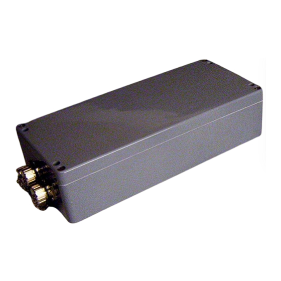
Components and Operation HG G-98780-A 4.3 Accessories (optional) 4.3.1 Serial/parallel Converter HG 06150ZA/XA Converter HG 06150XA for mounting bar installation Figure 12 The serial/parallel converter has a casing which is suitable for mounting bar installa- tion. To output the serial data via the RS 422 interface (ZA) or via RS232 (XA) the serial... -
Page 28: Software
Software HG G-98780-A Software The system can be configured via the antenna software. To enter the program, you have to connect the serial interface of an ordinary PC via an interface converter with the serial interface of the antenna. For antenna variants with RS422 interface (i.e. HG 98780ZA/XA) an appropriate interface converter is required. -
Page 29: 5.2 System Monitor
Software HG G-98780-A If you are using a different port than COM1 with HyperTerminal, then alter the port set- ting as follows: Select Properties from the File menu (or click the Icon ). The following window shows up (partly German version): Choose the respective port via the Direct to connection in the submenu. -
Page 30: Operating The Monitor Program
Software HG G-98780-A In order to start the monitor mode, first of all you have to switch the antenna off and on again. After 10 s (resp. 26 s) you can transfer the appropriate *.txt file from the disk with your terminal program. The following four files are on the disk: Mon3964r.txt... -
Page 31: Main Menu
Software HG G-98780-A 5.2.2.1 Main menu S:0568 X:+0000 Code: 00000000 Read: U[/mV]:24000 I[/mA]: 150 T[Grd.C]:+28 E: 0200 N: Ftx[/Hz]:105960 Prog_Code: 00000000 (W)rite Transponder Code (T)ime & Code (S)erial Output C(A)N-Parameters P(r)ofibus-Parameters (P)assword (L)oad Values to EEProm (E)rror ? Cs(v) (38,4 KB Code(5d),Sum(4d),Tr(1),Co(1),+-(1),Po(1),Cnt(1d)<crlf>) (B)oot Load Serv(i)ce Menu... - Page 32 Software HG G-98780-A Description of the system variables System status expression in hexadecimal notation. The single bits are explained in Table 9 „Possible system status mes- sages“ on page 21. Number of reading errors per transponder crossing. This value is stored until a new transponder has been detected. Display of the transmission frequency divided by 128.
-
Page 33: T)Ime & Code
Software HG G-98780-A 5.2.2.2 (T)ime & Code This menu enables the setting of timing values for the transponder decoding, the po- sition calculation and the positioning pulse. S:0544 X:+0000 Code: 00000000 Read: U[/mV]:24000 I[/mA]: 150 T[Grd.C]:+28 E: 0200 N: Ftx[/Hz]:105970 Prog_Code: 00000000 (L)evel for Positioning [10.1023]:... -
Page 34: S)Erial Output
Software HG G-98780-A 5.2.2.3 (S)erial Output Alterations within this menu need to be made effective by resetting the system (turn the antenna off and then on). Dependent upon the alterations made, it may be neces- sary to use a different baud rate / text document to call up the monitor (section 5.2.1 on page 29). -
Page 35: Figure 16 Output „(D)Isplay Telegram Content
Software HG G-98780-A Using „( )isplay Telegram Content“ it is possible to check the generated telegram (refer to Figure 16 on page 35). In this example the mask has the value 0xff. Press any key to return to the menu Serial Output. S:0547 X:+0000 Code: 00000000... -
Page 36: C(A)N Parameters
Software HG G-98780-A 5.2.2.4 C(A)N Parameters This menu enables setting the various CAN-Bus parameters. Before being able to use the CAN bus, it is necessary to activate this function by pressing ATTENTION! In case the CAN bus is not connected, it is essential to deacti- vate this function, as transmission errors will lead to antenna reset while the CAN bus it activated! SR = 00:... -
Page 37: P(R)Ofibus-Parameters
Software HG G-98780-A either activates the permanent output, according to the Clock for Sampling set in Time&Code (1; refer to 5.2.2.2 on page 33), or generates the output solely when a transponder is decoded within the reading range of the antenna (0). ... -
Page 38: Cs(V)
Software HG G-98780-A The header shows the current Profibus status. The following messages are possible: Profibus Status Messages NO_ERROR Profibus not active / without error DPS2_INI_ERROR These messages indicate that the Profibus hardware is either not equipped or faulty SPC_HW_ERROR USER_IO_DATA_LEN BUF_LEN_ERROR Inadmissible buffer lengths were specified in... -
Page 39: Software Update (Antenna Software)
Software HG G-98780-A Then hit the key within the main menu and a display with the following commands will appear: Open HEX- Flasher (Open the flash program) select the COM-Port which is currently used for the connection between the PC and the antenna prepare file input (Select the HEX file that is to be programmed) then press any key (Return to Hyperterm and hit any key) -
Page 40: Software Update
Software HG G-98780-A her.ini and Command.log. Open the function features (’Eigenschaften’) within the file menu of the Explorer and deactivate the parameter Writing Protected. In order to start the program now, carry out the file ST10-Flasher.exe. 5.3.2 Software Update While the software update is carried out, no other programs may occupy the used se- rial interface (COM-Port). -
Page 41: Figure 19 Update Program: Operating Elements
Software HG G-98780-A 1 Selection of the Hex file to be transmitted 2 Selection of the serial interface and baud rate 3 This option must always be activated 4 Start the programming procedure 5 Status messages 6 Exit the program Update program: Operating Elements Figure 19 Start the programming process by switching on the antenna and then click Program... -
Page 42: Figure 20 Update Program: Programing Procedure
Software HG G-98780-A Should an error occur during the transmission, red coloured status messages are output. As long as green coloured messages are out- put, the software update is cor- rect. The last 2 messages of a normal update procedure are: Program- Flash: Ok and CloseCom: Ok Update program: programing procedure Figure 20... -
Page 43: Maintenance
Maintenance HG G-98780-A Maintenance The system is largely maintenance free. Any maintenance is limited to visual examination of the antennas (ensuring all screws, cables and plugs are cor- rectly fastened) cleaning the ventilation openings if necessary. Document regularly the power consumption and power supply of each antenna. These values can be obtained from any menu in the monitor program. -
Page 44: Troubleshooting
Troubleshooting HG G-98780-A Troubleshooting The following table contains a list of errors that might occur. For each error, a symptom description is given. In the third column you will find a description of how to locate and possibly correct the error. If you should not be able to correct an occurring error, please use the table to locate the source of the error as exactly as possible (nature of malfunction, at which point in time did the error occur, etc.) before consulting us. -
Page 45: Technical Data
Technical Data HG G-98780-A Technical Data 8.1 Antenna Antenna HG 98780-A Casing Refer to Figure 7 on page 14 Effective antenna area refer to appendix, Section A on page 48 Power supply 24 V ±10 %, approx. 600 mA, approx. 2 A heating Protection Power supply (pin 1) 1 A slow-reacting Heating (pin 3) 3 A slow-reacting... -
Page 46: Table 24 Emc-Testing
Technical Data HG G-98780-A Antenna HG 98780-A Output serial The output requires 9.6 or 19.2 kbaud. The tele- (RS422 resp. RS232) gram content is configurable. 3964R or „transpar- ent“ procedures are available. Output CAN According to ISO/DIS 11898 identifier, Data rate, (HG 98780ZA/WA) Basic/Extended CAN;... -
Page 47: Parallel Converter (Optional)
5 g 11 ms / 2g 10 to 55 Hz Protection IP 55 Connector screw terminal Data input RS 422 (ZA), RS232 (XA) Data output 16+2, 24 V, 20 mA, not potentially separated Technical Data Parallel converter HG 06150ZA/XA (optional) Table 25 Englisch, Revision 14, Date: 07.02.2017... -
Page 48: Appendix
Appendix HG G-98780-A Appendix Effective Antenna Area The following 4 diagrams show the intensity of the reception voltage over the area of the antenna reading side for different reading distances. The scaling of this voltage corresponds to the sum voltage S output by the antenna (refer to Table 20 on page 31). -
Page 49: Figure 23 Diagram 3, Reception Voltage S Within The Antenna Area At Reading
Appendix HG G-98780-A Diagram 3, Reception voltage S within the antenna area at reading distance Figure 23 80 mm Diagram 4, Reception voltage S within the antenna area at reading distance Figure 24 100 mm Englisch, Revision 14, Date: 07.02.2017... -
Page 50: Figure 25 Diagram 5, Reception Voltage X Within The Antenna Area At Reading
Appendix HG G-98780-A The following two diagrams show the intensity of the positioning coil voltage within the antenna area for different reading distances. The voltage scaling corresponds the an- tenna voltage X (refer to Table 20 on page 31). Diagram 5, Reception voltage X within the antenna area at reading distance Figure 25 40 mm Diagram 6, Reception voltage X within the antenna area at reading distance... -
Page 51: B Positioning Accuracy
Appendix HG G-98780-A Positioning Accuracy The following diagrams show the location of the generation of the Posipuls within the antenna area at different reading distances and approach from left and right. Diagram 1, Location of the generation of the Posipulse at reading distance Figure 27 40 mm Diagram 2, Location of the generation of the Posipulse at reading distance... -
Page 52: Figure 30 Diagram 4, Location Of The Generation Of The Posipulse At Reading Di
Appendix HG G-98780-A Diagram 4, Location of the generation of the Posipulse at reading distance Figure 30 100 mm Location of Positioning Pulse Height/mm Direction of Travel /mm Diagram 5, Location of the generation of the Posipulse on the center axis at Figure 31 different reading distances Englisch, Revision 14, Date: 07.02.2017... -
Page 53: Attenuation Of The Reception Level Caused By Metal
Appendix HG G-98780-A Attenuation of the Reception Level caused by Metal Antenna (Reading Distance) Transponder HG 70661 Metal Sheet Attenuation of the reception level caused by metal Figure 32 Height h [cm] Signal [%] Dependency of the signal strength on the distance between transponder Table 26 and metal Englisch, Revision 14, Date: 07.02.2017... -
Page 54: D Influence Of Water
Appendix HG G-98780-A Influence of Water 3.15 in] in all cases. The signal strength level at this dis- Reading height was 80 mm [ tance in air represents 100 % in the following measurements. The water level was mea- sured from the bottom of the transponder. -
Page 55: E Mounting Next To Massive Metal Structures
Appendix HG G-98780-A Mounting next to Massive Metal Structures Recommended distances to massive metal structures Figure 35 Procedure 3964R For the computer interconnection between antenna <—> PLC a 3964R-Protocol may be used. As the antenna outputs data cyclically, this results in some simplifications for the implementation of the 3964R. -
Page 56: Data Direction Plc -> Antenna
Appendix HG G-98780-A T_QVZ for the programmable acknowledgement delay. (Figure 37) Status diagram procedure 3964R; Antenna —> PLC Figure 36 Data direction PLC -> Antenna In this direction, commands are transmitted only when required (e. g. when the refer- ence transponder is activated). To overcome the frequent cyclical data output of the antenna, the 3964R of the antenna has a lower priority (see Figure 36). -
Page 57: G Procedure „Transparent
Appendix HG G-98780-A Procedure „transparent“ For the interconnection antenna <—> PLC a transparent protocol may be used. The fol- lowing settings are necessary for the data transmission: 1 start bit, 8 data bit, even parity, 1 stop bit, baud rate 9600 Baud (default) or 19200 Baud. -
Page 58: 10 Handbook Conventions
Handbook Conventions HG G-98780-A 10 Handbook Conventions At the time this manual was printed, the following symbols and marks were used in all Götting KG documentations: For security advice, the following symbols stand for different degrees of danger and importance: NOTE! ATTENTION! WARNING! -
Page 59: List Of Figures
List of Figures HG G-98780-A 11 List of Figures Figure 1 Components..................5 Figure 2 Minimum iron-free area around Puck Transponder HG 70661..8 Figure 3 Mounting the antenna ............... 9 Figure 4 Position of the mounting holes ............9 Figure 5 Outline of the interface mounting bar case........ - Page 60 List of Figures HG G-98780-A stance 80 mm.................. 51 Figure 30 Diagram 4, Location of the generation of the Posipulse at reading di- stance 100 mm................52 Figure 31 Diagram 5, Location of the generation of the Posipulse on the center axis at different reading distances..........
-
Page 61: List Of Tables
Technical Data Antenna HG 98780-A..........45 Table 24 EMC-Testing..................46 Table 25 Technical Data Parallel converter HG 06150ZA/XA (optional) ..47 Table 26 Dependency of the signal strength on the distance between trans- ponder and metal................53 Englisch, Revision 14, Date: 07.02.2017... -
Page 62: Index
Index HG G-98780-A 13 Index Numerics positioning pulse 23 Profibus 25 3964R 55 LED 15, 17 Antenna line terminating resistor 15 Casing dimensions 14 Interfaces 19 Mounting 9 Maintenance 43 Socket connection plan 14 Monitor program 29 Technical Data 45 Parameter presettings 28 Working with 30 CAN 23... -
Page 63: 14 Copyright And Terms Of Liability
Copyright and Terms of Liability HG G-98780-A 14 Copyright and Terms of Liability 14.1 Copyright This manual is protected by copyright. All rights reserved. Violations are subject to pe- nal legislation of the Copyright. 14.2 Exclusion of Liability Any information given is to be understood as system description only, but is not to be taken as guaranteed features.
Need help?
Do you have a question about the HG 06150ZA and is the answer not in the manual?
Questions and answers