Table of Contents
Advertisement
Quick Links
Transponder-Antenna
HG G-71450/1/3/5-A
PosiPulse & Transponder-Code
Variants HG G-71450-A (RS232) / HG G-71451-A (PROFIBUS®) /
HG G-71453-A (CANopen®) / HG G-71455-A (PROFINET®)
English, Revision 07
Innovation through Guidance
Date: 31.08.2022
Dev. by: WM/LF
Author(s): RAD/WM/LF/RF
www.goetting-agv.com
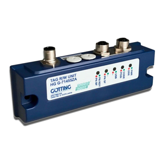
Transponder
Photo: Variant
HG G-71455ZA
Advertisement
Chapters
Table of Contents
Troubleshooting

Related Manuals for Gotting HG G-71450-A


Summary of Contents for Gotting HG G-71450-A
- Page 1 Transponder Transponder-Antenna HG G-71450/1/3/5-A PosiPulse & Transponder-Code Variants HG G-71450-A (RS232) / HG G-71451-A (PROFIBUS®) / HG G-71453-A (CANopen®) / HG G-71455-A (PROFINET®) English, Revision 07 Date: 31.08.2022 Dev. by: WM/LF Author(s): RAD/WM/LF/RF Photo: Variant HG G-71455ZA Innovation through Guidance...
- Page 2 Overview Summary Characteristics of the transponder antenna HG G-71450/1/3/5-A: • Transponder-Antenna for the posi- • Connectors (depending on the vari- tioning of automated guided vehi- ant): Up to 3x M12 cles (AGV) • Data interface (depending on the • Indoor, IP 65 variant): RS 232 (serial), PROFI- BUS®, CANopen®, PROFINET®...
-
Page 3: Table Of Contents
Table of Contents Contents About this Document..................6 Warning Notices............................6 1.1.1 Symbols..............................7 Definitions of Terms ..........................7 Abbreviations..............................7 Introduction....................8 Variants................................8 Additional Products............................9 Additional Documents........................... 10 Operating conditions..........................10 Application Examples for the Automation ................... 10 System Layout ............................11 Functional Description........................... 11 2.7.1 General Functional Description.................... - Page 4 Table of Contents 4.3.1 Mounting / Minimum Distances....................24 4.3.2 Variants with 409 kHz in connection with Energy Tracks..........25 4.3.3 Connection Cables..........................25 Interface HG 06150XA (optional for HG G-71450) ..............25 Commissioning ............................26 Interfaces: RS 232/serial (HG G-71450)...........27 Interface Parameter RS 232........................27 Telegram Setup ASCII Coding (SW5 = ON) .................28 Telegram Setup of Binary Coding (SW5 = OFF) ................29 Resetting the Antenna ...........................29...
- Page 5 Table of Contents 10.3 Programming via Interface Telegrams ..................60 10.3.1 HG G-71450: Programming via Serial Telegrams..............60 10.3.1.1 Structure of the Telegram (Host -> Antenna) ..............61 10.3.1.2 Structure of the Telegram (Antenna -> Host / if Transponder is not programmed)...........................
-
Page 6: About This Document
Chapter 1 – About this Document About this Document For you to be able to use your product simply and safely this device description uses consistent warning notices, symbols, terms and abbreviations. Those are described in the following sections. 1.1 Warning Notices In this device description warning notices appear before sequences of actions that may lead to damage to persons or property. -
Page 7: Symbols
About this Document – Chapter 1 1.1.1 Symbols In this device description the following symbols and formatting are used: If this information is ignored the product may not be operated in an optimal way. Indicates one or more links to the Internet. –... -
Page 8: Introduction
Chapter 2 – Introduction Introduction Data transmission between various objects (tool carriers, tools, vehicles, etc.) and the control system is crucial for ensuring the operating procedure. Movable objects must be identified and positioned quickly and reliably. Thereby identification sys- tems offer a safe, easy to install and economical solution. They can be used to man- age and monitor processes. -
Page 9: Additional Products
Introduction – Chapter 2 2.2 Additional Products The following products of Götting can be used with the transponder antenna (ob- serve the variants of the antenna). Rod transponders are usually installed in the ground, disc transponders usually on the ground. The rod transponders listed below have a slightly higher transmission power than the disc transponders. -
Page 10: Additional Documents
Chapter 2 – Introduction 2.3 Additional Documents Additional documents are sent upon request or available on our website. The QR-Code on the right leads you to our homepage www.goetting-agv.com. Below you will find links to the specific product pages. Transponders HG G-71325-A ... -
Page 11: System Layout
Introduction – Chapter 2 Identification of containers Management of loading and unloading processes Positioning of vehicles in production areas Location determination for public transport 2.6 System Layout The transponder antenna is usually mounted under a vehicle and connected to the vehicle computer (e. -
Page 12: Scope And Function
Chapter 2 – Introduction For some antenna variants, individual antennas can temporarily be deactivated via the data interface. This can be used, for example, if the antennas do not necessar- ily have to be used at the same time – e.g. if one is used to detect transponders in longitudinal direction, while the other is used for lateral driving. -
Page 13: Figure 4 Core Area Of The Reading Antenna With Positioning Pulse (Top View)
Introduction – Chapter 2 Only a maximum of one transponder is allowed in the detection area of the antenna at all times! The following image shows several transponders to explain the different transponder positions. Core area of the reading antenna with positioning pulse (top view) Figure 4 direction of travel F transponder... -
Page 14: Signals And Timing
Chapter 2 – Introduction 2.7.3 Signals and Timing Signals and Timing Figure 5 direction transponder antenna area 1 area 2 transponder detection area antenna length signals and timing data-free area (detection gap) DATA (NF) CD (level) Midpoint Crossover (positioning signal) = Midpoint pulse time (duty cycle of the PosiPuls) = 100 ms (not scaled) At first the data is „uncertain“... -
Page 15: Hardware
Hardware – Chapter 3 Hardware 3.1 Transponder The Götting transponders listed in Table 3 on page 9 are used as reference marks in the ground. The transponder code consists of 16 bits. 3.2 Transponder Antenna (Variants) 3.2.1 Applies to all Variants The antenna system is located in a 156.5 x 31 x 53 mm (L x D x H) housing made out of PC (polycarbonate). -
Page 16: Transponder Antenna Hg G-71450 (Rs 232)
Chapter 3 – Hardware Connection options PosiPulse Figure 6 HG G-7145x HG G-7145x Posi Posi Pulse Pulse Posi Posi Connection to a PLC Connection to a Relais 3.2.2 Transponder Antenna HG G-71450 (RS 232) The connection of the antenna occurs via a 5-pin cable. The ST 1 connector is a M12 circular connector (see Figure 7). -
Page 17: Leds
Hardware – Chapter 3 3.2.2.2 LEDs There are 4 LEDs for function control: HG G-71450: Meaning of the 4 LEDs Table 5 Meaning Indicates that operating voltage is available Carrier Detect, permanently lit when a transponder is in area I (see Figure 2 on page 12) DATA –... -
Page 18: Pin Assignments
Chapter 3 – Hardware 3.2.3.1 Pin Assignments HG G-71451: Pin assignment of the 5 pin circular connector ST1, male, A-coded Table 6 ST1, male, A-coded Assignment POSI out (20 mA) TxD (RS 232) *) RxD (RS 232) *) GND (data and supply) The specifications for TxD and RxD apply from the point of view of the antenna. -
Page 19: Switch-On Behaviour
Hardware – Chapter 3 3.2.3.3 Switch-On Behaviour The switch-on behavior follows the sequence described in section 3.2.1.1 on page 15 with one difference: The BUS LED is not switched on. 3.2.3.4 PROFIBUS®-Interface For this antenna the data as well as a status byte are transmitted via the PROFIB- US®. -
Page 20: Leds
Chapter 3 – Hardware HG G-71453: Pin assignment of the 5 pin circular connector ST2 (socket) Table 11 ST2, female, A-coded Assignment n. c. *) n. c. *) CAN_GND CAN_H CAN_L The pins 1 or 2 are connected between ST2 and ST3. HG G-71453: Pin assignment of the 5 pin circular connector ST3 (pin) Table 12 ST3, male, A-coded... -
Page 21: Transponder Antenna Hg G-71455-A (Profinet®)
Hardware – Chapter 3 3.2.5 Transponder Antenna HG G-71455-A (PROFINET®) The antenna is connected via a 5 pin and 4 pin cable. The connectors are M12 cir- cular connectors. Connection cable for ST 1 is available as an accessory (see Table 3 on page 9). -
Page 22: Leds
Chapter 3 – Hardware 3.2.5.2 LEDs There are 5 two-color LEDs for function control: Meaning of the 5 LEDs Table 16 Colour Meaning green indicates that operating voltage is available lights up in case of errors Code green lights up when a transponder is read POSI corresponds to the positioning output green... -
Page 23: Installation And Commissioning
Installation and Commissioning – Chapter 4 Installation and Commissioning During installation observe the operating conditions listed in section 2.4 on page 10. 4.1 Testing Transponders The transponders can be tested with the transponder antenna and a PC connected to it (see section 9.4 on page 52) 4.2 Installing Transponders Further information on installing the transponders can be found in the correspond- ing data sheets:... -
Page 24: Transponder Antenna
Chapter 4 – Installation and Commissioning 4.3 Transponder Antenna As an example, the following pictures show the HG G-71455 variant with PROF- INET® interface, as it has the largest external dimensions including the connectors. NOTICE Interferences from other antennas If several antennas are used in one system, overreach my cause interferences. Install antennas at a minimum distance of 1500 mm to each other or ... -
Page 25: Variants With 409 Khz In Connection With Energy Tracks
Installation and Commissioning – Chapter 4 For some antenna variants, individual antennas can be temporarily deactivated via the data interface. You can see which variants support the deactivation in Table 2 on page 8. 4.3.2 Variants with 409 kHz in connection with Energy Tracks 409 kHz variants of the antenna (all ZA variants, s. -
Page 26: Commissioning
Chapter 4 – Installation and Commissioning 4.5 Commissioning After the installation including the connection via the connection cable, the tran- sponder antenna is ready for operation. The interfaces and the configuration of de- viating interface parameters are described in the following chapters. Device Description HG G-71450/1/3/5-A | English, Revision 07 | Date: 31.08.2022... -
Page 27: Interfaces: Rs 232/Serial (Hg G-71450)
Interfaces: RS 232/serial (HG G-71450) – Chapter 5 Interfaces: RS 232/serial (HG G-71450) The transponder antenna HG G-71450 transmits the code of a transponder within the detection area via the serial interface. The output occurs according to the select- ed settings of the interface parameters (see below). If there is no transponder in the field, no protocols are sent. -
Page 28: Telegram Setup Ascii Coding (Sw5 = On)
Chapter 5 – Interfaces: RS 232/serial (HG G-71450) With SW4 the type of telegram output is adjusted: SW4 Position ON: When the transponder enters the antenna field of the reading antenna two identical data sets are output. Between both data sets there will be a pause of approx. -
Page 29: Telegram Setup Of Binary Coding (Sw5 = Off)
Interfaces: RS 232/serial (HG G-71450) – Chapter 5 5.3 Telegram Setup of Binary Coding (SW5 = OFF) Example: HG G-71450: Example for a binary telegram setup Figure 16 Check sum STX Start character (STX = 02 Hex) Sum of A and P results in 0 (Mod256). -
Page 30: Serial/Parallel Interface Hg G-06150Xa (Optional)
Chapter 5 – Interfaces: RS 232/serial (HG G-71450) 5.6 Serial/Parallel Interface HG G-06150XA (optional) HG G-71450: Optional interface HG G-06150Y for mounting bar installation Figure 17 The serial/parallel interface comes within a case suitable for top hat rail installation, see 4.4 on page 25. The serial data stream of RS 232 is supplied. Therefore the serial output of the antenna has to be set to CONT. -
Page 31: Interfaces: Profibus® (Hg G-71451)
Interfaces: PROFIBUS® (HG G-71451) – Chapter 6 Interfaces: PROFIBUS® (HG G-71451) The code supplied by the transponder has a sequence of 24 bits in which 16 bits are coded. The data and a status byte are output via the PROFIBUS®. The programming of transponders can also be carried out via the PROFIBUS®. -
Page 32: Status And Command Bits
Chapter 6 – Interfaces: PROFIBUS® (HG G-71451) The output bytes have to be used according to the following table: HG G-71451: Structure of the 3 PROFIBUS® output bytes Table 24 Byte # Length Type Sequence Meaning 2 Byte unsigned int Lo Byte Transponder code that is to be programmed... -
Page 33: Gsd File
Interfaces: PROFIBUS® (HG G-71451) – Chapter 6 6.5 GSD File You can download the latest version of the GSD file from our Internet server. http://www.goetting-agv.com/components/7145x Device Description HG G-71450/1/3/5-A | English, Revision 07 | Date: 31.08.2022... -
Page 34: Interfaces: Canopen® (Hg G-71453)
Chapter 7 – Interfaces: CANopen® (HG G-71453) Interfaces: CANopen® (HG G-71453) The code supplied by the transponder has a sequence of 24 bits in which 16 bits are coded. The data and a status byte are output via the CAN-Bus. Transponders can also be programmed via the CAN-Bus. -
Page 35: Table 28 Can: Pdo Operating Modes
Interfaces: CANopen® (HG G-71453) – Chapter 7 CAN: PDO operating modes Table 28 Operating mode Explanation Cyclic Every nth Sync telegram will transmit data Acyclic Sends if an event has occurred since the last Sync telegram Synchronous Data are transmitted after receipt of a Sync telegram Asynchronous Data is transmitted event-controlled Only on request by a remote frame... -
Page 36: Node Id
Chapter 7 – Interfaces: CANopen® (HG G-71453) 7.2 Node ID 2 Hex rotary switches protected by closing plugs in the housing of the transponder antenna can be used to adjust the CANopen® Node ID (see also Figure 9 on page 19). -
Page 37: Description Of The Receiving Process Data Objects (Rpdo)
Interfaces: CANopen® (HG G-71453) – Chapter 7 The status bits have the following meaning: HG G-71453: CAN transmitting object TPDO_1 – description of the status bits Table 34 Bit no. Value Description 0x80 Positioning pulse active (equivalent to the LED POS) 0x40 Transponder modulation detected (equiva- lent to the LED CD) -
Page 38: Heartbeat
Chapter 7 – Interfaces: CANopen® (HG G-71453) HG G-71453: CAN receiving object RPDO_1 – description of the command bits (part Table 36 2 of 2) Bit no. Value Description 0x04 Not used 0x02 PROG_CODE: The transition 0->1 of this bit gen- erates a programming command. -
Page 39: Object Directory
Interfaces: CANopen® (HG G-71453) – Chapter 7 7.8 Object Directory All objects relevant for the device are included in the CANopen® Object Directory. Each entry is indicated by a 16 bit index. Sub-components are indicated by a 8 bit sub index. RO indicates read only entries. The object index is subdivided into the fol- lowing areas: Overview of the object directory: HG G-71453: Communication specific entries in the range from 0x1000 to 0x1FFF... -
Page 40: Table 40 Hg G-71453: Manufacturer Specific Entries At 0X2000
Chapter 7 – Interfaces: CANopen® (HG G-71453) HG G-71453: Manufacturer specific entries at 0x2000 Table 40 Index Subindex Access Description 0x2000 Number of Manufacture Parameter Program transponder with 16 Bit Code Delete last transponder code (in order to make Posi Pulse fire again for the same code) 0x2001 Number of Parameter... -
Page 41: Table 46 Hg G-71453: Canopen® Directory: Software Version
Interfaces: CANopen® (HG G-71453) – Chapter 7 HG G-71453: CANopen® Directory: Software Version Table 46 Index Sub Index Name Type Attr. Default Description 0x100A Software Visible String „1.13“ Software version no. Version HG G-71453: Save Parameter Table 47 Index Sub Index Name Type Attr. -
Page 42: Table 51 Hg G-71453: Rpdo_1 Parameter
Chapter 7 – Interfaces: CANopen® (HG G-71453) HG G-71453: RPDO_1 Parameter Table 51 Index Sub Index Name Type Attr. Default Description 1400 TPDO_1 Unsigned 8 0x02 No. sub indices Parameter COB ID Unsigned 32 0x200 + PDO_1 valid, ID = Node-ID 0x200 + node-ID Transmission... -
Page 43: Table 54 Hg G-71453: Mapping Tpdo_1
Interfaces: CANopen® (HG G-71453) – Chapter 7 HG G-71453: Mapping TPDO_1 Table 54 Index Sub Index Name Type Attr. Default Description 1A00 number Unsigned 8 0x02 No. sub indices mapped objects Unsigned 32 0x61000110 Mapped to index mapped 0x6100,01 with a object length of 16 bit (Code 0..15) -
Page 44: Manufacture Parameters - Node Parameters
Chapter 7 – Interfaces: CANopen® (HG G-71453) 7.9 Manufacture Parameters - Node parameters HG G-71453: CAN: Manufacture Parameters - Node Parameters Table 56 Index Sub Index Name Type Attr. Default Description 0x2001 Number of Unsigned 8 0x03 No. sub indices Parameter Node Unsigned 8... -
Page 45: Transponder Programming
Interfaces: CANopen® (HG G-71453) – Chapter 7 HG G-71453: 8 Bit Digital Outputs Command Code Table 61 Index Sub Index Name Type Attr. Default Description 6200 number of Unsigned 8 0x01 No. of digital 8 bit 8 bit digital outputs outputs 8 bit digital Unsigned 8... -
Page 46: Interfaces: Profinet® (Hg G-71455)
Chapter 8 – Interfaces: PROFINET® (HG G-71455) Interfaces: PROFINET® (HG G-71455) The transponder antenna has an internal PROFINET® switch. The code transmitted by the transponder consists of a sequence of 24 bits in which 16 bits are coded. The data and a status byte are output via PROFINET®. Transpon- ders can also be programmed via PROFINET®. -
Page 47: Status Bits
Interfaces: PROFINET® (HG G-71455) – Chapter 8 8.3 Status Bits HG G-71455: Description of the PROFINET® status bits Table 65 Value Name Description Explanation 0x01 *) The status bit Code can be used to determine whether 0x02 Mirroring of the command bit there is a transponder in the 0x04 field whose code is being... -
Page 48: Software / Configuration
Chapter 9 – Software / Configuration Software / Configuration A monitor program runs in the antenna, to which a connection can be established with a PC. Depending on the antenna variant, this is done via the serial or USB inter- face. -
Page 49: Via The Usb Interface (Hg G-71455)
Software / Configuration – Chapter 9 Transmission parameters of the serial RS232 interface Table 67 Setting Baud rates – 38400 Baud (fixed for HG G-71451 and HG G-71453) – 19200 Baud – 9600 Baud (Standard for HG G-71450, Change via the DIP switches, see 5.1 on page 27) –... -
Page 50: Terminal Program
Chapter 9 – Software / Configuration Optionally the connection box M12-5-8-USB HG G-20960 can be inserted between antenna and PC (see also Table 3 on page 9). This allows the antenna to be con- nected via standard M12 cables and enables to supply the antenna with energy while it is connected to a PC. -
Page 51: Logging (Csv Output)
Software / Configuration – Chapter 9 From the menu File, select the sub item properties (or click on the icon The following window opens up: From the drop down connect via select the direct connection the corre- sponding port and confirm with . -
Page 52: Monitor Program (Service)
Chapter 9 – Software / Configuration Description of the values output via CSV (part 2 of 2) Table 69 Value Value range Description Code 0 – 65535 Transponder code TXOFF 1 = Transmitter part of the transponder antenna is switched off Level 0 –... -
Page 53: Main Menu Monitor Program Hg G-71451
Software / Configuration – Chapter 9 9.4.2 Main Menu Monitor Program HG G-71451 HG G-71451: Main menu of the monitor program Figure 21 HG71451 Monitor System 409kHz Profibus address: Current Transponder Code [hex/dez]: 9ABC / 39612 (H)ex Input Transponder Code [0..FFFF]: 9ABC (D)ez Input Transponder Code... -
Page 54: P)Osi Filter
Chapter 9 – Software / Configuration : Setting of a filter that can prevent the premature triggering of a positioning pulse in very slow vehicles, see section 9.4.3.2 on page 54. : CAN configuration, see section 9.4.3.3 on page 54. ... -
Page 55: Main Menu Monitor Program Hg G-71455
Software / Configuration – Chapter 9 If Autostart is deactivated, only the heartbeat message (if activated) is sent after turning the device on; the device is in the preoperational state. If Autostart is activated, the PDO and the heartbeat message (if activated) are sent immediately after turning the device on;... -
Page 56: Update Of The Operating Software (Firmware)
Chapter 9 – Software / Configuration 9.5 Update of the Operating Software (Firmware) 9.5.1 Via the RS 232 Interface (HG G-71450 / HG G-71451 / HG G-71453) Start the monitor program (see section 9.4 on page 52) and check the current firm- ... -
Page 57: Via The Usb Interface (Hg G-71455)
Software / Configuration – Chapter 9 With HyperTerminal you transfer the file as follows: From the Transmission menu, select the sub item send text file. The following window opens: Change to the directory or data carrier in which the firmware file is located and ... -
Page 58: Figure 27 Hg G-71455: Firmware Update - Choose File
Chapter 9 – Software / Configuration HG G-71455: Firmware update – choose file Figure 27 The DFU mode must be active as shown here Select .dfu file with Choose If the file was loaded correctly (status: File correctly loaded), execute the ... -
Page 59: Transponder Programming
Transponder Programming – Chapter 10 Transponder Programming The transponder antenna can also be used to program compatible transponders (see Table 3 on page 9). This is a two-stage process: Move the transponder to the correct position underneath the antenna Trigger the programming process in the transponder antenna (via interface tele- grams or the monitor program) For transponders that are yet unprogrammed no level is shown respectively the LED Data is not lit even when the transponder is in the antenna‘s reception area. -
Page 60: Programming Via The Monitor Program
Chapter 10 – Transponder Programming 10.2 Programming via the Monitor Program For this type of programming, the antenna must be connected to a PC on which a terminal program runs (see chapter 9 on page 48). Hold a transponder under the antenna as shown in Figure 30 on page 59. ... -
Page 61: Structure Of The Telegram (Host -> Antenna)
Transponder Programming – Chapter 10 10.3.1.1 Structure of the Telegram (Host -> Antenna) ASCII telegram with fixed start character, 4 bytes of data and a checksum. HG G-71450: Content of the telegrams sent by the host (ASCII mode) Table 71 Character Description Data type... -
Page 62: Structure Of The Telegram (Antenna -> Host / If Transponder Is Not Programmed)
Chapter 10 – Transponder Programming 10.3.1.2 Structure of the Telegram (Antenna -> Host / if Transponder is not programmed) This telegram type is sent once if the transponder has not been programmed. ASCII telegram with fixed start character, 4 bytes of data and a checksum. HG G-71450: Contents of the telegrams sent by the antenna (ASCII mode) Table 73 Character... -
Page 63: Hg G-71455: Programming Via Profinet® Telegrams
Transponder Programming – Chapter 10 The programming process is initiated by a rising edge of the PROG instruction bit, i.e. the transponder code to be programmed should first be transmitted with PROG=0. Then the same transponder code with PROG=1. This triggers the program- ming process which takes approx. -
Page 64: Maintenance
Chapter 11 – Maintenance Maintenance The system is largely maintenance-free. The maintenance is limited to the visual inspection of the antennas. checking all screws, seal plugs, cables and plugs for proper fastening and tight fit. If necessary, update the operating software according to the procedure described in section 9.5 on page 56. -
Page 65: Troubleshooting
Troubleshooting – Chapter 12 Troubleshooting Below you can find a list of possible errors in table form. A description of the symp- toms that occur is given for each error. In the third column you can find instructions on how to narrow down the error and, ideally, how to correct it. If you are unable to solve an error, please use the table to narrow it down as precisely as possible (type of malfunction, time of occurrence) before contacting us. -
Page 66: Table 75 Troubleshooting
Chapter 12 – Troubleshooting Troubleshooting (part 2 of 2) Table 75 Error Possible cause(s) Possible Diagnosis/Remedy Too early positioning pulses – due to metal loops in the floor too – Separate metal loops at the beginning of the small of a range 1-2 or 7-8 (see –... -
Page 67: Technical Data
Technical Data – Chapter 13 Technical Data Technical Data Transponder antenna (part 1 of 2) Table 76 Transponder antenna Dimensions 156.5 mm x max. 70 mm x 31 mm (L x H x D incl. con- nectors) *) Height depending on the antenna variant, see section 3.2 on page 15 Housing Polycarbonate (PC) - Page 68 Chapter 13 – Technical Data Technical Data Transponder antenna (part 2 of 2) Table 76 Transponder antenna max. crossing speed at (409 kHz) (125 kHz) nominal reading dis- tance HG G-71450 / HG G-71451 HG G-71450 / HG G-71451 / HG G-71453: / HG G-71453: –...
-
Page 69: List Of Figures
List of Figures – Chapter 14 List of Figures Figure 1 Block diagram system layout (example)................11 Figure 2 Detection area 1 and 2, data-free area D and nominal reading distance S, side view ............................12 Figure 3 Detection areas, top view......................12 Figure 4 Core area of the reading antenna with positioning pulse (top view)....... -
Page 70: List Of Tables
Chapter 15 – List of Tables List of Tables Table 1 Hazard classification according to ANSI Z535.6-2006............. 6 Table 2 Variant overview..........................8 Table 3 Additional products........................... 9 Table 4 HG G-71450: Pin assignment of the 5 pin circular connector ST 1, male, A-coded ...........................16 Table 5 HG G-71450: Meaning of the 4 LEDs ..................17... - Page 71 List of Tables – Chapter 15 Table 35 HG G-71453: Structure CAN receiving object RPDO_1 ..........37 Table 36 HG G-71453: CAN receiving object RPDO_1 – description of the com- mand bits ............................37 Table 37 HG G-71453: CAN coding of the device status ..............38 Table 38 HG G-71453: SDO telegram error codes................
- Page 72 Chapter 15 – List of Tables Table 76 Technical Data Transponder antenna ..................67...
-
Page 73: Index
Index – Chapter 16 Index Additional products.................9 GSD ......................7 AGV ......................7 GSD File..................... 33 Antenna system................15 Application Example..............10 Automation..................10 Hazard classification...............6 Hex rotary switch ..............31, 36 Cable....................9, 25 06150.............9, 10, 17, 25, 30 20960..................9, 50 Definitions................ - Page 74 Chapter 16 – Index PLC.......................11 Telegram setup ASCII ............28 PosiPulse..............7, 13, 15, 54 Telegram setup binary............29 Center signal ................14 Filter ....................54 Positioning accuracy..............23 Serial interface................48 positioning pulse................15 Software ....................48 PROFIBUS® ................17, 31 Switch-off Behavior..............15 Address..................31 Switch-on Behavior..............15 Configurations................31 Symbols ....................
-
Page 75: Copyright And Terms Of Liability
Copyright and Terms of Liability – Chapter 17 Copyright and Terms of Liability 17.1 Copyright This manual is protected by copyright. All rights reserved. Violations are subject to penal legislation of the Copyright. 17.2 Exclusion of Liability Any information given is to be understood as system description only, but is not to be taken as guaranteed features. - Page 76 Innovation through Guidance Götting KG Celler Str. 5 | D-31275 Lehrte Tel. +49 (0) 5136 / 8096 -0 Fax +49(0) 5136 / 8096 -80 info@goetting-agv.com www.goetting-agv.com www.goetting-agv.com...
Need help?
Do you have a question about the HG G-71450-A and is the answer not in the manual?
Questions and answers