Sign In
Upload
Manuals
Brands
Gotting Manuals
Antenna
HG G-98870
Gotting HG G-98870 Manuals
Manuals and User Guides for Gotting HG G-98870. We have
1
Gotting HG G-98870 manual available for free PDF download: Manual
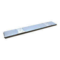
Gotting HG G-98870 Manual (124 pages)
1D Transponder Antenna with Continuous Localization
Brand:
Gotting
| Category:
Antenna
| Size: 6 MB
Table of Contents
Table of Contents
3
About this Document
7
Other Applicable Documents
7
Target Group
7
Validity
7
Presentation of Information
8
Symbols
8
Table 1 Hazard Classification According to ANSI Z535.6-2006
8
Warning Notices
8
Definitions
9
Figure 1 Reading and Mounting Side of the Transponder Antenna
9
Reading and Mounting Side
9
Table 2 Variant Overview HG G-98870-A
9
Variants of the Transponder Antenna
9
Coordinate System of the Transponder Antenna
10
Detection Area (Antenna Field) and Reading Area
10
Figure 2 Relative Coordinate System of the Antenna
10
Figure 3 Detection Area and Reading Area with Example of the Tolerance at the Edges of the Reading Area
10
Abbreviations
11
Table 3 Abbreviations
11
Improper Use
12
Intended Use
12
Safety Information
12
General Safety Information
13
Qualification of the Users
13
Obligations of the Operator
14
Required Accessories
15
Scope of Delivery
15
Table 4 Required Accessories
15
Optional Accessories
16
Table 5 Optional Accessories
16
Components in the Ground
17
Device Overview
17
Figure 4 System Components (Excerpt)
17
System Components
17
Transponder
17
Connections
18
Figure 5 Transponder Antenna HG G-98870-A (in the Photo Variant HG G- 98870ZA)
18
Reading Distances of the Transponders
18
Structure of the Transponder Code
18
Table 6 Reading Distances of the Transponders
18
Transponder Antenna
18
Displays (Leds)
19
Table 7 Leds Transponder Antenna HG G-98870ZA CAN Bus
19
Table 8 Leds Transponder Antenna HG G-98870YA PROFINET
19
Busy Mode
20
Figure 6 Example of an RMG Crane
21
Operating Principle
21
Position Detection with Transponders
21
Track Guidance with Transponders
22
Storage
23
Mounting
24
Mounting the Transponders
24
Operating Conditions for Transponders
24
All Variants: Connecting POWER
25
Preparation of Connection Cables
25
Table 10 Pin Allocation POWER (M12, 5 Pin, a Coded)
25
Table 9 Connectors of the Antenna Variants
25
All Variants: Connecting Ethernet
26
Table 11 Pin Allocation Ethernet (M12, 4 Pin, D Coded)
26
Table 12 Pin Allocations CAN1 and CAN2 (M12, 5 Pin, a Coded)
26
Variant HG G-98870ZA: Connecting the CAN Bus
26
Minimum Distance between Antenna and Transponder
27
Mounting the Transponder Antenne
27
Operating Conditions of the Antenna
27
Table 13 Pin Allocations PN1 and PN2 (M12, 4 Pin, D Coded)
27
Variant HG G-98870YA: Connecting PROFINET
27
Figure 8 Minimum Distance between Identical Transponder Antennas
28
Figure 9 Minimum Distance to Current-Carrying Wires Around the Transponder an
28
Minimum Distance between Transponder Antennas
28
Minimum Distance to Current-Carrying Wires Around the Transponder Antenna and Metal-Free Areas
28
Connection Example
29
Mounting / Attaching the Antenna to the Vehicle
30
Figure 12 Dimensions of the Transponder Antenna HG G-98870-A, Pictured with the Optional Mounting Brackets
31
Figure 13 Components of the Optional Mounting Kit
31
Mounting with the Optionally Available Mounting Kit HG Z-98870-001
31
Figure 14 Mounting the Optional Mounting Kit
32
Commissioning
33
Connecting the Antenna to a Computer
33
Establish the Ethernet Connection
33
Switch on the Antenna
33
Adjust Ethernet Settings
34
Figure 15 Connection Example: Connection to the Ethernet Interface of a Computer
34
Figure 16 Example: Ethernet Settings of the Computer
34
Configuring the Antenna Via the Configuration Web
35
Figure 17 Basic Menu of the Antenna after Successfully Calling up the Web
35
Opening the Web
35
Minimize Interferences by Adjusting the Thresholds
36
Set Parameters
36
Completing Commissioning
37
Figure 18 Connection Example USB Connection with the USB Interface of a PC
38
Interfaces
38
Usb
38
CAN Bus
39
Definitions CAN and Canopen
39
Operating Modes and States
39
Table 14 Definitions Can/Canopen
39
Table 15 Canopen®: Parameter PDO Operating Mode
39
Can
40
CAN Message Object - Main Telegram
40
Table 16 Canopen®: PDO Operating Modes
40
Table 17 CAN: Bit and Byte Sequences
40
Table 18 Canopen® Operation Mode
40
Table 19 Structure of the CAN Message Object - Main Telegram
41
Additional Telegram Transponder Slot Transponder 1
42
Additional Telegram Transponder Slot Transponder 2
42
CAN Message Object - Additional Telegrams
42
Table 20 CAN Status: Possible System States
42
Table 21 Structure of the CAN Message Object Transponder 1 (Additional Telegram 1)
42
Table 22 Structure of the CAN Message Object Transponder 2 (Additional Telegram 2)
42
Additional Telegram Other Data
43
CAN Message Object - Receive Object
43
Table 23 Structure of the CAN Message Object Other Data (Additional Telegram 3)
43
Table 24 Structure of the CAN Message Object - Receive Object
43
Canopen
44
Canopen® Txpdo_1 - Main Telegram, Send Object
44
Description of the Transmit Process Data Objects (Txpdo)
44
Table 25 CAN Rx Command
44
Table 26 Variables in Txpdo_1 (Main Telegram)
44
Canopen® Txpdo_2 - Additional Telegram 1, Send Object
45
Canopen® Txpdo_3 - Additional Telegram 2, Send Object
45
Canopen® Txpdo_4 - Additional Telegram 3, Send Object
45
Description of the Service Data Objects (Sdos)
45
Table 27 Variables in Txpdo_2 (Additional Telegram 1)
45
Table 28 Variables in Txpdo_3 (Additional Telegram 2)
45
Table 29 Variables in Txpdo_4 (Additional Telegram 3)
45
CAN EDS Configuration File
46
Input Bytes
46
Object Directory
46
Profinet
46
Table 30 Identifier for Read and Write Access
46
Table 31 Possible Error Codes SDO Telegram
46
Table 32 Structure of the PROFINET® Input Bytes
46
Output Bytes
47
Table 33 Structure of the PROFINET® Output Bytes
47
Table 34 PROFINET® RX Command
47
Dynamic Auto-Tune
48
GSDML File
48
Configuring the System Via the Configuration Web
49
Introduction
49
Using the Configuration Web
49
Basic Menu
50
Figure 19 Configuration Web Pages: Basic Menu (Status - Antenna Diagram)
50
Header, Menu Column and Status Column
50
Table 35 List of the Menus of the Configuration Web
50
Figure 20 Configuration Web Pages: Status Column
51
Table 36 Configuration Web Pages: List of Possible Error and Warning Messages
51
Figure 21 Configuration Web Pages: Status Column - Login Status
52
Login / Logout
52
Figure 22 Configuration Web Pages: Login
53
Figure 23 Configuration Web Pages: Logout
53
Figure 24 Configuration Web Pages: Save and Cancel Button
53
Login
53
Logout
53
Set Parameters and Save Them Permanently
53
Table 37 Configuration Web Pages: Parameter Types
54
Figure 25 Configuration Web Pages: Status - Measurement
55
Status - Measurement
55
Table 38 Configuration Web Page: Status - Measurement: List of Output Fields
55
Figure 26 Configuration Web Pages: Status - Antenna Diagram
57
Status - Antenna Diagram
57
Figure 27 Configuration Web Pages: Status - Errors
58
Status - Errors
58
Table 39 Configuration Web Pages: Status - Errors: List of Possible Error Messag
58
Chapter 22 - List of Tables
59
Table 40 Configuration Web Pages: Status - Errors: List of Possible Warnings
59
Configuration - Settings
60
Figure 28 Configuration Web Pages: Configuration - Settings
60
Table 41 Configuration Web Pages: Parameter Adjustment Transmitter Coil
60
Tune Transmitter Coil
60
Detected Threshold
61
Table 42 Configuration Web Pages: Parameter Detected Threshold
61
Mounting Configuration
62
Table 43 Configuration Web Pages: Parameter Mounting Configuration
62
Configuration - CAN Bus
63
Figure 29 Mounting Direction: Mounting Positions Normal and Inverted
63
Figure 30 Configuration Web Pages: Configuration - CAN-Bus, CAN Format Canopen
64
Figure 31 Configuration Web Pages: Configuration - CAN-Bus, CAN Format CAN
64
Table 44 Configuration Web Pages: Parameter CAN-Bus
64
Configuration - Logging
66
Configuration - Network
66
Figure 32 Configuration Web Pages: Configuration - Network
66
Figure 33 Configuration Web Pages: Configuration - Logging
66
Table 45 Configuration Web Pages: Configuration - Network
66
Configuration - Security
67
Table 46 Configuration Web Pages: Configuration - Logging
67
Figure 34 Configuration Web Pages: Configuration - Security
68
Table 47 Configuration Web Pages: Configuration - Security - Top Section
68
Configuration - Restart
69
Figure 35 Configuration Web Pages: Configuration - Restart
69
Table 48 Configuration Web Pages: Configuration - Security - Lower Section
69
Configuration File
70
Figure 36 Configuration Web Pages: Configuration - Restart Query
70
Figure 37 Configuration Web Pages: Configuration - Restart Message
70
Table 49 Configuration Web Pages: Configuration - Restart
70
Figure 38 Configuration Web Pages: Configuration File
71
Table 50 Configuration Web Pages: Configuration File - Upload
71
Figure 39 Configuration Web Pages: Transponder List
72
Table 51 Configuration Web Pages: Configuration File - Download
72
Transponder List
72
Chapter 21 - List of Figures
73
Figure 40 Configuration Web Pages: Transponder List Upload - Security Prompt
73
Table 52 Configuration Web Pages: Transponder List - Upload
73
Table 53 Configuration Web Pages: Transponder List - Download
73
Figure 41 Configuration Web Pages: Update Firmware
74
Table 54 Configuration Web Pages: Update Firmware
74
Update Firmware
74
Figure 42 Configuration Web Pages: Update Bootloader
75
Update Bootloader
75
Figure 43 Configuration Web Pages: Update Bootloader - Security Prompt
76
Figure 44 Configuration Web Pages: Update Bootloader - Update OK
76
Table 55 Configuration Web Pages: Update Bootloader
76
Emergency Update
77
Normal Firmware Update
77
Update Antenna Software
77
Configuration File
78
Figure 45 Format of the Transponder List Using the Example of Notepad++® (Left) and Microsoft® Excel® (Right)
79
Format of the CSV File
79
Structure of the Transponder List
79
Transponder List
79
Figure 46 Example of a System with Transponders and Tracks
80
Internal Sequence of the Transponder List
80
Table 56 Example: Section of a Transponder List for Figure 46
80
Table 57 Example: Internally Sorted Transponder List
80
Checking the Transponder List
81
Determining the IP Address of the Antenna
82
Figure 47 Screenshot IP-Config V100.Exe
82
Maintenance
84
Disposal
85
Figure 48 Sequence Sketch: Normal Operation of the Transponder Antenna with Transponder Identification
86
Normal Operation
86
Operation with Transponder Recognition and Plausibility Checks
86
Figure 49 Sequence Diagram: Antenna Reads First Transponder (FIRST_TRANSP)
87
First_Transp
87
Err_No_Code
88
Err_Transp_Not_Find
88
Figure 50 Sequence Diagram: Antenna Does Not Read Code (ERR_NO_CODE)
88
Err_Not_Next_Transp
89
Figure 51 Sequence Diagram: Read Transponder Is Not the Previous/Next in the Transponder List (ERR_NOT_NEXT_TRANSP)
89
Err_Illogical_Transp
90
Figure 52 Sequence Diagram: Difference between Transponder Positions Greater than
90
Err_Equal_Transp
91
Err_Pos_Dif_T1_T2
91
Figure 53 Sequence Diagram: Two Transponders in the Field Have the same Code
91
Error Table
92
Table 58 Error Table
92
Troubleshooting
92
Reducing Interferences
95
Table 59 Technical Data Antenna HG G-98870-A
97
Technical Data
97
Technical Data of the Transponder Antenna
97
Dimensional Drawing of the Transponder Antenna
98
Figure 54 Dimensional Drawing of the Antenna with Dimensions, with the Opt
98
Appendix
99
Communication-Specific Entries in the Range 0X1000 to 0X1Fff
99
Overview of the Canopen® Directory
99
Table 60 Overview Canopen® Object Directory I
99
Details of the Canopen® Directory
101
Device Type
101
Standardized Device Profile from 0X6000
101
Table 61 Overview Canopen® Object Dictionary II
101
Table 62 Canopen® Directory: Device Type
101
COB-ID SYNC Message
102
Device Name
102
Error Register
102
Hardware Version
102
Producer Heartbeat Timer
102
Software Version
102
Table 63 Canopen® Directory: Error Register
102
Table 64 Canopen® Directory: COB-ID SYNC Message
102
Table 65 Canopen® Directory: Device Name
102
Table 66 Canopen® Directory: Hardware Version
102
Identity Object
103
Table 69 Canopen® Directory: Identity Object
103
Table 70 Canopen® Directory: Transmit PDO_1 Communication Parameter 0
103
Table 71 Canopen® Directory: Transmit PDO_2 Communication Parameter 1
103
Transmit PDO_1 Communication Parameter 0
103
Transmit PDO_2 Communication Parameter 1
103
Table 72 Canopen® Directory: Transmit PDO_3 Communication Parameter 2
104
Table 73 Canopen® Directory: Transmit PDO_4 Communication Parameter 3
104
Transmit PDO_3 Communication Parameter 2
104
Transmit PDO_4 Communication Parameter 3
104
Table 74 Canopen® Directory: Transmit PDO_1 Communication Parameter 0 (Abs Pos)
105
Table 75 Canopen® Directory: Transmit PDO_2 Communication Parameter 1 (Slot 1)
105
Transmit PDO_1 Mapping Parameter 0 (Abs Pos)
105
Transmit PDO_2 Mapping Parameter 1 (Slot 1)
105
Table 76 Canopen® Directory: Transmit PDO_3 Communication Parameter
106
Table 77 Canopen® Directory: Transmit PDO_4 Communication Parameter
106
Transmit PDO_3 Mapping Parameter 2 (Slot 2)
106
Transmit PDO_4 Mapping Parameter 3 (Other)
106
32-Bit Digital Input (Transmission in TPDO_2 and TPDO_3)
107
8-Bit Digital Input (Transmission in TPDO_1 and TPDO_4)
107
8-Bit Digital Output
107
Table 81 Canopen® Directory: 8-Bit Digital Output
107
16-Bit Digital Output
108
8-Bit Analog Digital Input (Transmission in TPDO_4)
108
Table 82 Canopen® Directory: 16-Bit Digital Output
108
Table 83 Canopen® Directory: Canopen®-RX-Command
108
Table 84 Canopen® Directory: 8-Bit Analog Digital Input (Transmission in TPDO_4)
108
32-Bit Analog Digital Input (Transmission in TPDO_1)
109
Do_4)
109
Logging with Tera Term
109
Table 85 Canopen® Directory: 16-Bit Analog Digital Input
109
Table 86 Canopen® Directory: 32-Bit Analog Digital Input (Transmission in TPDO_1)
109
Figure 55 Tera Term File Dialog for Logging
110
Record Logging
110
Figure 56 Tera Term Connection Setup
111
Start Logging
111
Figure 57 Tera Term During Logging
112
List of Figures
113
List of Tables
115
Index
118
Revision History
121
Copyright
122
Copyright and Terms of Liability
122
Exclusion of Liability
122
Trade Marks and Company Names
122
Advertisement
Advertisement
Related Products
Gotting HG G-98780-A
Gotting HG G-98760-C Series
Gotting HG G-98810-C
Gotting HG G-98830
Gotting HG G-98870-A
Gotting HG G-98870 ZA
Gotting HG G-98870 YA
Gotting HG G-98835
Gotting HG G-19334-A
Gotting HG G-19334
Gotting Categories
Antenna
GPS
Accessories
Marine Radio
Controller
More Gotting Manuals
Login
Sign In
OR
Sign in with Facebook
Sign in with Google
Upload manual
Upload from disk
Upload from URL