Table of Contents
Advertisement
Quick Links
Device Description
Positioning and Identification
English, Revision 03
Date: 12.07.2011
Götting KG, Celler Str. 5, D-31275 Lehrte - Röddensen (Germany), Tel.: +49 (0) 51 36 / 80 96 -0,
Fax: +49 (0) 51 36 / 80 96 -80, E-Mail: techdoc@goetting.de, Internet: www.goetting.de
Antenna
— CANopen ® —
HG 71453-A
Dev. by:
Author(s):
W.M.
RAD / L.S. / S.M.
HG 71453-A
Advertisement
Chapters
Table of Contents

Related Manuals for Gotting HG 71453-A


Summary of Contents for Gotting HG 71453-A
- Page 1 Device Description HG 71453-A Positioning and Identification Antenna — CANopen ® — HG 71453-A English, Revision 03 Dev. by: W.M. Date: 12.07.2011 Author(s): RAD / L.S. / S.M. Götting KG, Celler Str. 5, D-31275 Lehrte - Röddensen (Germany), Tel.: +49 (0) 51 36 / 80 96 -0,...
-
Page 2: Table Of Contents
Transmission Range and Function ..........6 1.4.3 Signals and Timing ................ 7 Components and Operation ..........8 Components in the Ground (Transponders) ......8 Identifying Antenna HG 71453-A (CAN open®) ......8 2.2.1 Pin Allocations................9 2.2.2 LEDs ................... 10 2.2.3... - Page 3 Contents HG 71453-A Monitor Program ..............24 4.2.1 Programming of a Transponder of Type HG 71325 ....... 25 4.2.2 CAN Menu ................... 26 4.2.3 Update of the Internal Software (Firmware) ........27 Technical Data ..............29 EDS File ................. 30 List of Pictures ..............
-
Page 4: Identification Systems
The low-cost antenna HG 71453-A offers identification as well as positioning. 1.1 Application Examples for the Automation... -
Page 5: System Configuration
Identification Systems HG 71453-A 1.3 System Configuration Reading Station Interpreter Serial output of the read transponder code and the positioning pulse Reading antenna Data carrier System configuration Figure 1 1.4 Functional Description 1.4.1 General Functional Description When the antenna crosses a transponder it supplies it with energy by an alternating electromagnetic field. -
Page 6: Transmission Range And Function
Identification Systems HG 71453-A 1.4.2 Transmission Range and Function The field intensity of the magnetic alternating field decreases with an increasing dis- tance between transponders and reading antenna. Thus the information exchange is only feasible within a certain area. The field length L and the field width B of the transmission range (see Figure 2 on page 6) will be defined via the parallel centre line through the reading antenna (road). -
Page 7: Signals And Timing
Identification Systems HG 71453-A 1.4.3 Signals and Timing With the transponders HG 71310, HG 71320 and HG 71325. Transponder (Data Carrier) Zt: Positioning pulse time = 100 ms Signals and Timing Figure 3 Initially the data are insecure and the signal strength is still small (range II). Approach- ing further the signal becomes stronger and can be read completely. -
Page 8: Components And Operation
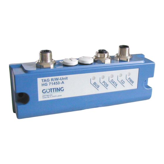
HG 71370-W is able to change the positioning mode. The transponder code provides 16 Bit serially or parallel. 2.2 Identifying Antenna HG 71453-A (CAN open®) The antenna system is in a 53 x 31 x 156.5 mm casing (polycarbonate). The antenna is connected by 5-pole cables. -
Page 9: Pin Allocations
Components and Operation HG 71453-A 2.2.1 Pin Allocations Allocation POSI out (20 mA) TxD (RS 232) *) RxD (RS 232) *) GND (Data and Supply) *) TxD and RxD refer to the antenna. Pin alloc. of the 5-pin circular connector ST1 (male) -
Page 10: Leds
Components and Operation HG 71453-A 2.2.2 LEDs 5 LEDs are provided for function control Description Indicates that operating voltage is supplied, device is ON Shines steadily, if a transponder is located in area I (see Figure 2 on page 6) -
Page 11: Heartbeat
Components and Operation HG 71453-A It is also possible to permanently deactivate a TxPDO by selecting the asynchronous mode (255) with inhibit time = 0 and Event_time = 0, then store the parameters. In ad- dition, it is possible to temporarily deactivate/activate the TxPDO by setting/deleting the highest ranking bit within the corresponding PDO COB Identifier [1800,01]. -
Page 12: Description Of The Service Data Objects (Sdos)
Components and Operation HG 71453-A 2.2.5.3 Description of the Service Data Objects (SDOs) The service data object is used to access to the object index. An SDO is always trans- mitted with a confirmation, i. e. each reception of the message is acknowledged. The... -
Page 13: Table 11 Canopen® Directory: Manufacturer Specific Entries At 0X2000
Components and Operation HG 71453-A Index Subindex Access Description EEProm 0x1011 Number of entries of Restore Default Parameter Restore Default all 0x1017 Producer Heartbeat Time 0x1018 Number of entries of Identity Object Vendor ID Product Code Revision 0x1800 Number of entries of Transmit... -
Page 14: Table 12 Canopen® Directory: Standardised Device Profile Area In The Range
Components and Operation HG 71453-A 0x6000 Number of 8 Bit Inputs Status bits (see Table 7 on page 11) 0x6100 Number of 16 Bit inputs Transponder code bits 0..15 ® CANopen Directory: Standardised device profile area in the range from... -
Page 15: Table 18 Canopen® Directory: Save Parameter
Components and Operation HG 71453-A Index Sub Ind. Name Type Attr. Map Default Description 0x1010 Save Parameters Unsigned 8 0x01 No. of sub indices Save All Unsigned 32 RW No 0x00000001 Save All is possible ® CANopen Directory: Save Parameter Table 18 By writing the signature ’save’... -
Page 16: Table 22 Canopen® Directory: Transmit Pdo_1 Parameter
Components and Operation HG 71453-A Index Sub Ind. Name Type Attr. Map Default Description 1800 TxPDO_1 Param- Unsigned 8 0x05 No. of sub indices eter COB ID Unsigned 32 RW No 0x180 + PDO_1 valid, Node ID ID = 0x180 + Node ID... -
Page 17: Manufacture Parameters - Node Parameters
Components and Operation HG 71453-A 2.2.5.5 Manufacture Parameters - Node Parameters Index Sub Ind. Name Type Attr. Map Default Description 0x2001 Number of Unsigned 8 0x03 No. of sub indices Parameter Node Baud rate Unsigned 8 RW No 0x04 125 Kbaud *) -
Page 18: Node Address
Components and Operation HG 71453-A Index Sub Ind. Name Type Attr. Map Default Description 0x6100 number of 16 bit Unsigned 8 0x01 No. of 16 bit inputs digital inputs 16 bit digital input Unsigned 16 RO Yes ./. 16 bit transponder code CANopen®... -
Page 19: Mounting And Setup
Mounting and Setup HG 71453-A Mounting and Setup 3.1 Testing a Transponder It is possible to test the transponders with a reading antenna and a connected PC (see section 4.2 on page 24). 3.2 Mounting a Transponder Approx. 150 mm... -
Page 20: Mounting In Very Solid Ground (E. G. Concrete)
Mounting and Setup HG 71453-A To protect the transponder use either a covering cap or apply an epoxy resin layer (thickness approximately 1 cm). The drill hole mouth should be wide enough so that the cover cannot press on the transponder. -
Page 21: Connection
Mounting and Setup HG 71453-A All indications refer to the position of the ferrite rod in the antenna: Direction of Travel mounting level metal-free metal-free area area Position of the ferrite rod Nominal reading distance / position of the antenna ferrite rod Figure 7 3.3.2... -
Page 22: Software
Software HG 71453-A Software Transponder Programming and Update of the Internal Software The antenna has to be switched into the monitor mode, i. e. connect the serial interface of a PC / laptop with the appropriate pins (Rx and Tx) of the antenna. Then start the terminal program (see below). -
Page 23: Parameter Settings
Software HG 71453-A Subsequently you will be asked to insert your Setup- CD into your CD- ROM drive. Install the CD and click on icon .Confirm all installation messages. Hyper Terminal will be installed and is then ready for use. -
Page 24: Monitor Program
Software HG 71453-A 4.2 Monitor Program After connection set-up has been effected (see above) enter in the terminal pro- gram. The following display will appear: HG 71453 Monitor System: 409 kHz / Code [hex-dez]: FEDC - 65244 / Status: 61... -
Page 25: Programming Of A Transponder Of Type Hg 71325
Software HG 71453-A 4.2.1 Programming of a Transponder of Type HG 71325 With you can enter the desired transponder code in hexadecimal form, use decimal input. Hold the transponder close to the reading device as shown below. ... -
Page 26: Can Menu
Software HG 71453-A 4.2.2 CAN Menu From within the main menu press to open the CAN menu. HG 71453 Monitor System: 409 kHz / Code [hex-dez]: FEDC - 65244 / Status: 61 Node ID [hex]: 02 / CAN online : Operational / int.Status: 0000... -
Page 27: Update Of The Internal Software (Firmware)
Software HG 71453-A 4.2.3 Update of the Internal Software (Firmware) Please check the current Firmware-version first with Reader HG71453 (c) Goetting KG ---------------- 71454A11.00B 11.07.05 ---------------- Modul Date X39300W5 300103 I39300W5 251104 71454SIO 040705 T39300W5 010705 H39300W5 010705 GETEDIT... - Page 28 Software HG 71453-A Now it is possible to transmit the new Firmware by ASCII-Upload. Using HyperTerminal you transmit the file in the following way: In the menu transmission choose the subitem Send Textfile. The follow- ing window will open: Switch to the directory or to the data carrier in which the downloaded files are stored and choose the corresponding firmware- file (e.g.
-
Page 29: Technical Data
0 to +50 Storage temperature -20 to +70 *) These values refer to the position of the ferrite rod in the antenna (see Figure 7 on page 21) Technical Data Antenna HG 71453-A Table 31 English, Revision 03, Date: 12.07.2011... -
Page 30: Eds File
EDS File HG 71453-A EDS File You can download the latest version of the EDS file from our internet server. Please open the following URL http://www.goetting.de/en/search/gallery/71453 in order to find and download the latest version of that CAN bus configuration file. -
Page 31: List Of Pictures
Length and width of the interception area (view from above)..... 6 Figure 3 Signals and Timing ................7 Figure 4 Antenna dimensions HG 71453-A ............8 Figure 5 Mounting proposal and metal-free area around the transponder HG 71325................... 19 Figure 6 Mounting of the identifying antenna: Position and size of the drilling holes .................... -
Page 32: List Of Tables
CANopen® Directory: 8 Bit Digital Inputs (transmitted in TxPDO 1) 17 Table 29 CANopen® Directory: 16 Bit Digital Inputs ........18 Table 30 Terminal settings for the monitor program ........23 Table 31 Technical Data Antenna HG 71453-A ..........29 English, Revision 03, Date: 12.07.2011... -
Page 33: Index
Index HG 71453-A Index CAN 10 CANopen 10 application examples 4 maintenance 21 CAN open 8 monitor program Company names 35 terminal settings 23 Copyright 35 mounting drill holes 20 deviation from centre 6 range 19 reading antenna 20 registration gap 6... -
Page 34: Handbook Conventions
Handbook Conventions G_71451-A 10 Handbook Conventions In documentations of Götting KG the following symbols and assignments are being used at the time of printing this manual: Security advices have the following symbols, depending on the emphasis and the degree of exposure: NOTE! ATTENTION! CAUTION! -
Page 35: Copyright And Terms Of Liability
Copyright and Terms of Liability HG 71453-A 11 Copyright and Terms of Liability 11.1 Copyright This manual is protected by copyright. All rights reserved. Violations are subject to pe- nal legislation of the Copyright. 11.2 Exclusion of Liability Any information given is to be understood as system description only, but is not to be taken as guaranteed features.
Need help?
Do you have a question about the HG 71453-A and is the answer not in the manual?
Questions and answers