Table of Contents
Advertisement
Quick Links
Device Description
Identification Antenna
English, Revision 06
Date: 14.12.2016
Götting KG, Celler Str. 5, D-31275 Lehrte - Röddensen (Germany), Tel.: +49 (0) 51 36 / 80 96 -0,
Fax: +49 (0) 51 36 / 80 96 -80, eMail: techdoc@goetting.de, Internet: www.goetting.de
Positioning and
— 128 kHz —
HG G-98760-C
Dev. by:
W.M.
Author(s).:
RAD / A.F / L.S.
HG G-98760-C
Advertisement
Chapters
Table of Contents

Related Manuals for Gotting HG G-98760-C Series


Summary of Contents for Gotting HG G-98760-C Series
- Page 1 Device Description HG G-98760-C Positioning and Identification Antenna — 128 kHz — HG G-98760-C English, Revision 06 Dev. by: W.M.
-
Page 2: Table Of Contents
Contents HG G-98760-C Contents Introduction ...............5 System Components ............... 5 Function ................. 5 Positioning ................6 Mounting ................7 Installation / Commissioning ..........8 Components and Operation ..........13 HG 98760ZC/WC (with CAN bus) .......... 13 4.1.1 Drawing..................13 4.1.2 Plug Allocations for 12-pin socket ..........14 HG 98760YC/XC (with Profibus).......... - Page 3 Contents HG G-98760-C System Monitor..............27 5.2.1 How to start the monitor program ..........27 5.2.1.1 Prozedur Monitor only ............. 27 5.2.1.2 Prozedur 3964R/transparent ........... 27 5.2.2 How to work with the monitor program ......... 28 5.2.2.1 Main Menu................28 5.2.2.2 (T)ime &...
- Page 4 Contents HG G-98760-C 14.1 Copyright................54 14.2 Exclusion of Liability ............. 54 14.3 Trade Marks and Company Names........54 English, Revision 06, Date: 14.12.2016...
-
Page 5: Introduction
Introduction HG G-98760-C Introduction The described antenna is especially suited for vehicles in outdoor areas, as the elec- tronic units are sealed within the antenna case. It is possible to adjust all important set- tings and values after manufacturingoftware as well as proceeding software updates via a serial interface. -
Page 6: 1.3 Positioning
Introduction HG G-98760-C Further, different characteristics of the antenna, like for example current consumption and supply voltage, can be measured and added to the output protocol. The serial output signal is a non-isolated RS 232 or RS 422. The positioning pulse is also galvanically isolated +24 V (20 mA) switched output. -
Page 7: Mounting
Mounting HG G-98760-C Mounting Inside the casing are four drill holes for four M5 screws. Make sure that the antenna is mounted correctly! Check the ori- ATTENTION! entation of the antenna thoroughly! Place for mounting (vehicle, ...) Reading direction (Transponder) 4 screws, type M5 (not included in scope of supply) Direction of travel... -
Page 8: Installation / Commissioning
Installation / Commissioning HG G-98760-C Installation / Commissioning NOTE! Check the operating voltage before connecting! Although the RS 422 interface reacts largely insensitive to interferences, the cable should not lie directly beside power supply cables. Establish all required connections. For the next commissioning steps connect a laptop with the antenna via a RS 422 to RS 232 interface (not in the scope of supply). - Page 9 Installation / Commissioning HG G-98760-C The following diagrams show examples for protocolled data: Low interference Diagram: commissioning protocol / low interference; sum voltage over the Figure 3 track In the diagram the sum voltage over the track is shown. Noise (inference) is located at 50 sampels, the signal at 950.
- Page 10 Installation / Commissioning HG G-98760-C Whenever a transponder is crossed, initially the sum voltage will increase. Once the Threshold for Decoding has been reached, the bit TRANS_IN_FIELD is being set. It takes 4 x 8 ms (= 4 datapoints) for the transponder code to be decoded. The duration depends on the setting of Number of Equal Codes in menu Time &...
- Page 11 Installation / Commissioning HG G-98760-C Interfered Decoding (function still existing) Diagram: Commissioning protocol / interfered decoding (function still exist- Figure 6 ing) The following diagram shows a case in which false POSI-Pulses may be generated through wrongly set parameters for Threshold for Decoding and/or Threshold for Positioning.
- Page 12 Installation / Commissioning HG G-98760-C For this example, the thresholds are set to 100 samples. The bit TRANS_IN_FIELD is permanently set. Following a successful transponder decoding, initially a correct POSI-Pulse is generated. However, as the software does not realize that the tran- sponder leaves the antenna field (the noise is higher than the set 100 samples for the thresholds), each zero crossing of the difference voltage (not shown in the diagram) will generate another POSI-Pulse.
-
Page 13: Components And Operation
Components and Operation HG G-98760-C Components and Operation 4.1 HG 98760ZC/WC (with CAN bus) Positioning antenna HG 98760ZC/WC Figure 8 The antenna and interpreter electronics are housed in a 360 x 160 x 91 mm casing. The reading area is the upper side of the housing. The cover is located on top of the casing. -
Page 14: Plug Allocations For 12-Pin Socket
Components and Operation HG G-98760-C 4.1.2 Plug Allocations for 12-pin socket contact 98760ZC 98760WC +24 V (antenna) GND (antenna) +24 V (heater) GND (heater) +RX (RS 422) RX (RS232) -RX (RS 422) not connected +TX (RS 422) Tx (RS232) -TX (RS 422) not connected + Posi Pulse (see 4.2.2 on page 15) - Posi Pulse (see 4.2.2 on page 15) -
Page 15: Pin Allocations
Components and Operation HG G-98760-C Antenna and interpreting electronics are housed in a 360 x 160 x 91 mm casing. The reading side of the antenna is the top of the casing with the casing cover. The three built-in 12 pin sockets (M23; gold-plated contacts) are facing in the direction of travel. For each antenna, a correspondingly suitable line termination resistance is included in the scope of supply. -
Page 16: Switch-On Characteristics
Components and Operation HG G-98760-C Contact HG 98769YC HG 98760XC Rx (RS232) + RX (RS422) not connected - RX (RS422) Tx (RS232) + TX (RS422) not connected - TX (RS422) + Posi Pulse (see below) - Posi Pulse (see below) not connected signal ground casing... -
Page 17: Interfaces
Components and Operation HG G-98760-C 4.2.4 Interfaces 4.2.4.1 Serial (RS 232 or RS422) The serial output may be configured in several ways. The transmission rate is adjust- able between 9600 and 19200 Baud, the output protocol may be chosen as either “transparent“... -
Page 18: Table 6 Possible System Status / Error Messages
Components and Operation HG G-98760-C Byte # Length Valency Type Description 2 Byte 0x0000.0008 unsigned int Voltage generated by the transponder within the frame antenna in samples 10,11 2 Byte 0x0000.0010 signed int Voltage generated by the transponder within the difference antenna in samples 1 Byte 0x0000.0020 unsigned char... -
Page 19: List Of System Commands
Components and Operation HG G-98760-C Valency Name Description 0x1000 POSIPULS transponder crossed center of the antenna **) 0x2000 0x4000 0x8000 Possible system status / error messages (Section 2 of 2) Table 6 As soon as the transponder leaves the antenna field these bits are deleted This bit is deleted when the transponder leaves the antenna field or after a chosen time (refer to 5.2.2.2 on page 30) -
Page 20: System Monitor
Components and Operation HG G-98760-C command Check Meaning Procedure Start sign parameter byte 3964R ASCII activate reference transponder trans- parent ASCII List of system commands Table 7 Further information concerning number: The monitor mode should not be used during normal operation (e. g. from an PLC), as the following output is not according to a transparent or 3964R protocol but only suitable for display on a VT52-terminal and used for the alteration of parameters. -
Page 21: Can Message Object 1 (Transmission Object, Compatible To Former Firmware Versions)
Components and Operation HG G-98760-C 4.2.4.3.2 CAN Message Object 1 (transmission object, compatible to former firmware versions) Byte # Length Type Meaning 2 Byte unsigned int System status according to Table 6 on page 18 3,4,5,6 4 Byte unsigned long 32 bit transponder code 1 Byte unsigned char... -
Page 22: Can Message Object 4 (D Identifier, Transm. Object)
Components and Operation HG G-98760-C 4.2.4.3.5 CAN Message Object 4 (D identifier, transm. object) Byte # Length Type Meaning 2 Byte unsigned int System status according to Table 6 on page 18 2 Byte unsigned int 16 Bit transponder code 2 Byte unsigned int sum voltage... -
Page 23: Output Byte
Components and Operation HG G-98760-C Number of Byte # Length Type Order of bytes *) Meaning Input Bytes applied antenna voltage 1 Byte unsigned char [x 100 mV] current consumption 1 Byte unsigned char [x 10 mA] measured temperature within 1 Byte unsigned char antenna [... -
Page 24: Table 14 Output Format Serial/Parallel Interface
Components and Operation HG G-98760-C The serial/parallel interface is housed within a case suitable for mounting bar installa- tion. To output the serial data via the RS 422 interface, the serial output of the antenna has to be set to transparent protocol with the data content CODE (lower 16 Bit), DEL- TA_X and system status as follows: Use 7 as length of the telegram and 100B as value for the Telegram Content Mask (as shown in Figure 19 on page 34) in the correspond- ing menu. -
Page 25: Software
Software HG G-98760-C Software The system can be configured via the antenna software. To enter the program, you have to connect the serial interface of a PC via an interface converter with the RS 422- interface of the antenna. Then start a terminal program on the PC. NOTE! The interface converter is not part of the systems scope of sup- ply. -
Page 26: Parameter Presettings
Software HG G-98760-C Now check in the window that there is a marker before HyperTerminal (ja = ; no = ). If yes, the program is installed on your system and you can click here (2 x) and switch to the next section. If no, set one with mouse/key- board and close both windows with Afterwards you will be asked to install your Setup-CD into your CD-ROM drive. -
Page 27: 5.2 System Monitor
Software HG G-98760-C Choose the respective port via the connect to entry in the submenu. Confirm with . Save the altered values iwhen you are asked for it when finishing HyperTerminal. 5.2 System Monitor In the monitor mode the system can be configured with the help of a menu. To use the monitor mode you need to know which protocol is adjusted in your antenna. -
Page 28: How To Work With The Monitor Program
Software HG G-98760-C With HyperTerminal the file is transferred as follows: Choose Send Text file in the menu Transfer. The following window will be opened: Switch to disk drive (in our example, the files are located on the hard disk) and select the respective *.txt file. -
Page 29: Table 16 Description Of The System Variables (Monitor Program)
Software HG G-98760-C Each of the screen menus contains important system variables in the first line (refer also to Table 16), as they also appear in the output telegram (described in section 4.2.4.1.1 on page 17). The last line on the screen contains possible status messages, if e.g. -
Page 30: T)Ime & Code
Software HG G-98760-C )N-Parameter (section 5.2.2.5 on page 35) )ofibus parameter (section 5.2.2.6 on page 36) )rite Transponder (section 5.2.2.9 on page 37) )-Out (section 5.2.2.6 on page 36) )pdate firmware (section 5.2.2.9 on page 37) ... - Page 31 Software HG G-98760-C When using RW transponders, the free high bits are searched for a preset value (0-F). This value may be preset under and has to be programmed into the transponders together with the desired code. If a value > F (e.g. 10) is entered, the monitoring is switched off.
-
Page 32: F)Requency And Antenna Tuning
Software HG G-98760-C 5.2.2.3 (F)requency And Antenna Tuning S:0006 X:+0007 Code: 00000000 Read: Frx[/Hz]:66800 Ftx[/Hz]:127970 U[/mV]:22500 I[/mA]: 290 T[Grd.C]:+28 E: 0000 N: (R)x_Frequency [/Hz]: 1553000 ( 66750 Hz) A(u)to-Tune (A)ntenna-Tuning [0..15,+,-]: switch (T)ransmitter: (Q)uit Menue Menu: (F)requency And Antenna Tuning Figure 16 ... -
Page 33: S)Erial Output
Software HG G-98760-C 5.2.2.4 (S)erial Output Alterations within this menu become effective by resetting the system (turn the antenna off and then on). Depending upon the alterations made, it may be necessary to use a different baud rate/ text document to call up the monitor (section 5.2.1 on page 27). S:0021 X:+0004 Code: 00000000... - Page 34 Software HG G-98760-C S:0021 X:+0006 Code: 00000000 Read: Frx[/Hz]:66880 Ftx[/Hz]:127960 U[/mV]:24200 I[/mA]: 240 T[Grd.C]:+28 E: 0800 N: 1 Bytes from Position: 1 Dummy 2 Bytes from Position: 2 CODE_H(L) 2 Bytes from Position: 4 CODE_L(H) 2 Bytes from Position: 6 SUM_1 2 Bytes from Position: 8 DIF_X...
-
Page 35: C(A)N-Parameter
Software HG G-98760-C 5.2.2.5 C(A)N-Parameter This menu enables setting the various CAN Bus parameters: SR = 00: NO ERROR (C)AN active E(X)tended CAN STANDARD (I)dentifier: TX/RX [0..2047]: (A)-Identifier: [0..2047]: (B)-Identifier: [0..2047]: (D)-Identifier: [0..2047]: CAN-Ba(u)drate[20,50,125,250,500,1000 kB]:1000 B(R)P Baudrate Prescaler [0..63]: (S)JW Sync Jump Width [0..3]: Tseg(1) [2..15]:... -
Page 36: P(R)Ofibus Parameter
Software HG G-98760-C 5.2.2.6 P(r)ofibus Parameter In this menu the Profibus parameters can be altered. ATTENTION! If the Profibus is not connected or an antenna without Profibus is used, it is strongly recommended to deactivate the Profibus, as its activation causes transmission errors which lead to a reset of the antenna! Byte # Master-Input... -
Page 37: W)Rite Transponder
Software HG G-98760-C allows to turn the Profibus on or off. When switched on it is initialized with the Slave address as specified with With you can choose whether the highest byte is output first or last (see Table 13 on page 22). -
Page 38: Software Update (Antenna Software)
Software HG G-98760-C After the programmation is complete change to Hyperterm, wait 10 seconds und con- nect to the COM port again. Then run the monitor mode again. 5.3 Software Update (Antenna Software) It is possible to update the software of the integrated interpreters via the serial inter- face using a portable PC. - Page 39 Software HG G-98760-C 1 Selection of the Hex file to be transmitted 2 Selection of the serial interface and baud rate 3 This option must always be activated 4 Start the programming procedure 5 Status messages 6 Exit the program Update program: Operating Elements Figure 22 Start the programming process by switching on the antenna and then click Program...
- Page 40 Software HG G-98760-C Should an error occur during the transmission, red coloured status messages are output. As long as green coloured messages are out- put, the software update is cor- rect. The last 2 messages of a normal update procedure are: Pro- gramFlash: Ok and Clo- seCom: Ok Update program: Operating Elements...
-
Page 41: Maintenance
Maintenance HG G-98760-C Maintenance The system is largely maintenance free. Any maintenance is limited to visual examination of the antennas (ensuring all screws, cables and plugs are cor- rectly fastened) cleaning the ventilation openings if necessary Document regularly the power consumption and power supply of each antenna. These values can be obtained from any menu in the monitor program. -
Page 42: Trouble Shooting
Trouble Shooting HG G-98760-C Trouble Shooting The following list contains a list of errors that might occur. For each error, a symptom description is given. In the third column you will find a description how to locate and possibly correct the error. If you should not be able to correct an error occurred, please use the table how to lo- cate the source of the error as exactly as possible (nature of malfunction, at which point in time did the error occur, etc.) before consulting us. -
Page 43: Technical Data
Technical Data HG G-98760-C Technical Data 8.1 Antenna Antenna HG 98760-C Casing refer to Figure 9 on page 13 Effective antenna area 280 x 110 mm (positioning range) Power supply 24 V ±10 %, ca. 600 mA, about 2A heater Necessary protection Supply (Pin 1) 1 A inert Heating (Pin 3) 3 A inert... -
Page 44: 8.2 Parallel Converter
Technical Data HG G-98760-C Antenna HG 98760-C CAN-Bus (Version According to ISO/DIS 11898 Identifier, Data rate, HG 98760ZC/WC) Basic/Extended CAN; configurable via serial inter- face Profibus (Version According to DIN 19245 / EN 50170 HG 98760YC/XC) automatic searching of baud rates; supported rates: 9.6 kBd, 19.2 kBd, 93.75 kBdm 187.5 kBd, 500 kBd, 1.5 MBd, 3 MBd, 6 MBd, 12 MBd;... - Page 45 Technical Data HG G-98760-C Electromagnetic Compatibility (EMC) of Antenna HG 98760-C Checking of Preliminary Test Standards Static electric discharge EN 61000-4-2 Signal connections Highfrequency asymmetrical EN 61000-4-6 Quick transients EN 61000-4-4 DC connections Highfrequency asymmetrical EN 61000-4-6 Impulse voltages EN 61000-4-5 EMC-Testing Table 21 a.
-
Page 46: Appendix
Appendix HG G-98760-C Appendix Physical Basics Field Arrangement of the Energy Field Field arrangement of the energy field f =128 kHz Figure 24 Field Arrangement of the Transponder’s Reverse Signal Difference Antenna Sum Antenna Field arrangement of the transponder’s reverse signal f =64 kHz Figure 25 English, Revision 06, Date: 14.12.2016... -
Page 47: Induced Voltages In Sum And Difference Antenna
Appendix HG G-98760-C Induced Voltages in Sum and Difference Antenna Transponder direction of movement Difference Induced voltages in sum- and difference antenna Figure 26 Procedure 3964R For the computer interconnection between antenna <—> PLC a 3964R-Protocol may be used. As the antenna outputs data cyclically, this results in some simplifications for the implementation of the 3964R. -
Page 48: Data Direction Plc -> Antenna
Appendix HG G-98760-C (Figure 28) Status diagram procedure 3964R; Antenna —> PLC Figure 27 Data direction PLC -> Antenna In this direction, commands are transmitted only when required (e. g. when the refer- ence transponder is activated). To overcome the frequent cyclical data output of the antenna, the 3964R of the antenna has a lower priority (see Figure 27). -
Page 49: C Procedure „Transparent
Appendix HG G-98760-C Procedure „transparent“ For the interconnection antenna <—> PLC a transparent protocol can be used. The fol- lowing settings have to be observed for the data transmission: 1 start bit, 8 data bit, parity even, 1 stop bit, Baudrate 9600 Baud (default) or 19200 Baud. -
Page 50: 10 List Of Pictures
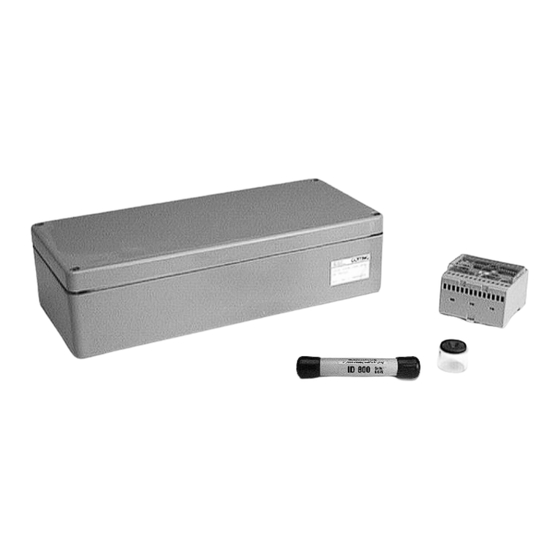
List of Pictures HG G-98760-C 10 List of Pictures Figure 1 System Components ................5 Figure 2 Mounting the antenna................7 Figure 3 Diagram: commissioning protocol / low interference; sum voltage over the track ....................9 Figure 4 Commissioning protocol / decoding of the transponder without any problems.................... -
Page 51: List Of Tables
List of Tables HG G-98760-C 11 List of Tables Table 1 Available versions of HG G-98760-C..........6 Table 2 Pin allocation of 12-pin socket (CAN bus) ........14 Table 3 Allocation of 12-pin Profisbus connectors X1 and X2 (see Figure 10 on page 14).................. -
Page 52: Index
Index HG G-98760-C 12 Index Numerics interfaces 17 CAN 20 3964R 47 positioning pulse 20 RS 232 17 Antenna 13 casing dimensions 13 monitor program 27 interfaces 17 how to 28 mounting 7 parameter presettings 26 technical data 43 output telegram 17 Company names 54 Copyright 54 Procedure „transparent“... -
Page 53: 13 Handbook Conventions
Handbook Conventions HG G-98760-C 13 Handbook Conventions At the time this manual was printed, the following symbols and marks were used in all Götting KG documentations: For security advices, the following symbols stand for different degrees of danger and importance: NOTE! ATTENTION! WARNING! -
Page 54: 14 Copyright And Terms Of Liability
Copyright and Terms of Liability HG G-98760-C 14 Copyright and Terms of Liability 14.1 Copyright This manual is protected by copyright. All rights reserved. Violations are subject to pe- nal legislation of the Copyright. 14.2 Exclusion of Liability Any information given is to be understood as system description only, but is not to be taken as guaranteed features.
Need help?
Do you have a question about the HG G-98760-C Series and is the answer not in the manual?
Questions and answers