Table of Contents
Advertisement
Quick Links
Technical Description
2-dim. Positioning and
Identification Antenna Outdoor
English, Revision 04
Date: 19.01.2015
Götting KG, Celler Str. 5, D-31275 Lehrte - Röddensen (Germany), Tel.: +49 (0) 51 36 / 80 96 -0,
Fax: +49 (0) 51 36 / 80 96 -80, eMail: techdoc@goetting.de, Internet: www.goetting.de
HG 98860ZA
Dev. by:
Author(s):
HG 98860ZA
WM / MH / DF
RAD / AF
Advertisement
Chapters
Table of Contents

Related Manuals for Gotting HG 98860ZA


Summary of Contents for Gotting HG 98860ZA
- Page 1 Technical Description HG 98860ZA 2-dim. Positioning and Identification Antenna Outdoor HG 98860ZA English, Revision 04 Dev. by: WM / MH / DF Date: 19.01.2015...
-
Page 2: Table Of Contents
Antenna HG 98860ZA ............. 8 Installation / Commissioning ..........10 Components and Operation ..........15 Components in the Ground ........... 15 4.1.1 Transponders ................15 Transmitter-Receiver Antenna HG 98860ZA ......15 4.2.1 Connection .................. 17 4.2.2 Turn-on characteristics ..............17 4.2.3 Interfaces .................. - Page 3 Contents HG 98860ZA 5.3.2.1 Main menu................33 5.3.2.2 (S)erial Output ................ 35 5.3.2.3 (T)ime & Code ................ 37 5.3.2.4 (F)requency & Antenna Tuning ..........38 5.3.2.5 C(A)N-Parameters ..............39 5.3.2.6 Cs(v) ..................40 5.3.2.7 Display (X)Histogram / (-)............41 5.3.2.8 Display (Y)Histogram / (+) ............
- Page 4 Contents HG 98860ZA 14.3 Trade Marks and Company Names........59 English, Revision 04, Date: 19.01.2015...
-
Page 5: Introduction
Examples of automated vehicles using transponder systems Figure 1 Antenna HG 98860ZA utilizes a completely new antenna concept, which has a large reading area with a linear transponder positioning function. The antenna is so-called 2-dimensional, meaning that it outputs the Transponder code as well as the linear de- viation rectangular to the direction of travel, in direction of travel and in addition the information “Crossing of the transponder“. -
Page 6: System Components
Introduction HG 98860ZA 1.1 System Components The 2-dimensional Positioning and Identification System using the antenna HG 98860ZA consists of up to four different components: HG 70653ZA System components (optional extras in brackets) Figure 2 Transmitter-receiver antenna HG 98860ZA incl. interpreter... -
Page 7: Application Example
Introduction HG 98860ZA The internal interpreter unit decodes the Transponder code and interpolates the Tran- sponder position rectangular to the direction of travel and in direction of travel from the measured values. Each coordinate axis crossing in direction of travel generates a positioning pulse of adjustable duration. -
Page 8: Installation
For the same reason, the transponder should be mounted as vertically aligned as possi- ble. Please refer to the data sheet/mounting instructions for the transponder. 2.2 Antenna HG 98860ZA Antenna dimensions Figure 5... - Page 9 Installation HG 98860ZA To preserve the antenna body and especially avoid any dents or cracks in the area of the mounting holes we would strongly recommend the following steps: Apply the combined rubber / plastic washers with approx. 90 mm diameter to secure a better distribution of the pressure.
-
Page 10: Installation / Commissioning
5.3.2.3 on page 37), it is useful to record a complete test run over the set track. The serial interface of antenna HG 98860ZA may be used accordingly (refer to section 5.3.2.6 on page 40). In addition to this you can use the TxD 232 debug interface (section 4.2.3.4 on page 27). -
Page 11: Figure 7 Diagram: Commissioning Protocol / Insignificant Interference Level; Shown Is The Sum Voltage Over The Travelled Distance
Installation / Commissioning HG 98860ZA The following diagrams show examples of logged system data: Low Interference Level Diagram: Commissioning Protocol / insignificant interference level; shown is Figure 7 the sum voltage over the travelled distance The above diagram shows the sum voltage (in units) over the travelled distance. The noise is in this case approx. -
Page 12: Figure 9 Diagram: Commissioning Protocol / High Interference Level; Shown Is The Sum Voltage Over The Traveled Distance
Installation / Commissioning HG 98860ZA During each Transponder crossing, the sum voltage increases initially. Once the threshold Threshold Decoding has been exceeded, the bit TRANS_IN_FIELD is set. Following 4 x 8 ms (= 4 data points) the Transponder code is decoded. The duration depends on the setting for Number of Equal Codes within the menu Time &... -
Page 13: Figure 10 Diagram: Commissioning Protocol / Jammed Decoding (Function Still Ensured)
Installation / Commissioning HG 98860ZA Jammed Decoding (function still ensured) Diagram: Commissioning Protocol / jammed decoding (function still en- Figure 10 sured) The following diagram shows a case in which false POSI-Pulses are generated through wrongly set parameters for Threshold for Decoding and/or Threshold for Positioning. - Page 14 Installation / Commissioning HG 98860ZA For this example, the thresholds are set to 100 units. The bit TRANS_IN_FIELD is per- manently set. Following a successful Transponder decoding, initially a correct POSI- Puls is generated. However, as the software does not realize that the Transponder...
-
Page 15: Components And Operation
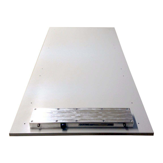
The following environmental conditions have no effect on the system: snow, ice, water. oil, tar, earth, dirt, etc. 4.2 Transmitter-Receiver Antenna HG 98860ZA This antenna has RS 422 and CAN interfaces. Photo Transmitter-Receiver Antenna HG 98860ZA Figure 12... -
Page 16: Figure 13 Drawing Antenna Hg 98860Za (With Casing Dimensions)
The ca- ble (the connecter) exits at one side of the antenna. Drawing Antenna HG 98860ZA (with casing dimensions) Figure 13 The interpreter is integrated in the antenna casing. The electronics are varnished. A thermostat controlled heater is included. -
Page 17: Connection
Connection 16-pin Antenna connection socket Figure 14 The antenna is equipped with a 16 pin connection socket. The pin allocation is as fol- lows: Contact HG 98860ZA (RS 422) Socket (pin) +24 V (antenna) front view GND (antenna) n.c. SL Rx... -
Page 18: Interfaces
Components and Operation HG 98860ZA Following this period of time, the actual program starts. If configured accordingly (also refer to Figure 21 on page 38), the transmission coils will be automatically tuned. This procedure takes another 16 seconds. 4.2.3 Interfaces 4.2.3.1... -
Page 19: Table 2 Data Words In A Telegram With 21 Byte Length
Components and Operation HG 98860ZA Table of the data words of a telegram with 21 byte length. Byte # Length Value Type Description 1 Byte 0x0000.0001 ASCII-061 : „=“ Start pulse (Default: „=“) 2 Byte 0x0000.0002 signed short Y-Position: Y [mm] (lateral deviation) within the range of -750 .. -
Page 20: Table 3 Possible System Status Messages
Components and Operation HG 98860ZA In the following table you will find a list of the binary codes used to describe the system status (for byte # 20 and 21 in Table 2): Value Name Description 0x0001 DEC_HW_ERROR code decoder hardware error... - Page 21 Components and Operation HG 98860ZA The antenna approaches a transponder: voltages S and D increase once the voltages S or D exceed the set „Threshold Decoding/Calculation“ the counter „number of readings“ is reset to 0 the status bit „TRANS_IN_FIELD“ (0x200) is set codes are decoded and the counter „number of readings“...
-
Page 22: List Of Commands
Components and Operation HG 98860ZA 4.2.3.1.2 List of commands A command telegram always consists of four bytes, including the actual command and the parameters. When using the procedure „transparent“ it is, in addition, necs- sary to transfer one start character and a check sum (XOR operation of all bytes in- cluding the start character). - Page 23 Components and Operation HG 98860ZA Command Parameter Check Procedure Start Description Bytes Bytes Set tuning value to 3 3964R ASCII trans- parent ASCII Set tuning value to 4 3964R ASCII trans- parent ASCII > Set tuning value to 5 3964R...
- Page 24 Components and Operation HG 98860ZA Command Parameter Check Procedure Start Description Bytes Bytes Set tuning value to 11 3964R ASCII trans- parent ASCII Set tuning value to 12 3964R ASCII trans- parent ASCII Set tuning value to 13 3964R ASCII...
-
Page 25: System Monitor
Components and Operation HG 98860ZA 4.2.3.1.3 System Monitor The system may be configured via menus in monitor mode. Refer to section 5.3 „Sys- tem Monitor“ on page 31. 4.2.3.2 CAN Bus 4.2.3.2.1 Description of the CAN Protocol It possible to configure the Basic or the Full-CAN-Mode. The CAN parameters are set via the system monitor. -
Page 26: Can Message Object 2 (Transmission Object)
Components and Operation HG 98860ZA 4.2.3.2.4 CAN Message Object 2 (Transmission Object) Byte # Length Type Description 2 Byte unsigned short Voltage within the sum antenna gener- ated by the Transponder 2 Byte signed short Voltage within the difference antenna... -
Page 27: Can Message Object 4 (Reception Object)
Components and Operation HG 98860ZA 4.2.3.2.6 CAN Message Object 4 (Reception Object) It is possible to send commands to the antenna. For this it is necessary to send a Mes- sage Object with the same address as Message Object 1 and a length of 6 bytes. -
Page 28: Software Download
Components and Operation HG 98860ZA Deviation Y (mm) TRANS_IN_FIELD (Bit) ESTIMATE (Bit) COILSEL (Bit) It is, for example, possible to record this data with the terminal program Hyperterm, save it as *.csv file and interpret it accordingly (refer to section 5.3.2.6 on page 40). - Page 29 Components and Operation HG 98860ZA Contact Wire no. / Color Allocation — n. c. RS 232 TxD for data logging Shield * = Rx and Tx relative to the antenna. Connection cable pin allocation (part 2 of 2) Table 10...
-
Page 30: Software
PC to the serial interface of the antenna. For the antenna type HG 98860ZA either the Götting adapter cable HW CAB00113 (see section 5.4.2 on page 44) or an interface converter RS 422 ->... -
Page 31: System Monitor
Software HG 98860ZA If you are using a different port than COM1 with HyperTerminal, then adjust the port as follows: Select Properties from the menu file (or click the Icon ). The following window appears: Choose the direct connection to the respective port via the submenu direct connection. -
Page 32: How To Work With The Monitor Program
Software HG 98860ZA Montrans.txt Transfer if the system is adjusted to procedure Transparent with “HighByte first“. The file contains the characters: 0x3D 0x4D 0x4F 0x4E 0x49 0x38 in hexa-decimal notation. Transmon.txt Transfer if the system is adjusted to procedure Transparent with “LowByte first“. -
Page 33: Main Menu
Software HG 98860ZA 5.3.2.1 Main menu S:0005 D:+005 D_Y:+32767 D_X:+32767 Code: 0000 Read: 0: N: Frx[/Hz]:61280 Ftx[/Hz]:127990 CSEL: 1 U[/mV]:24200 I[/mA]: 340 T[Grd.C]:+14 S_MA: 8002 S_SL: 0000 Noise (S)erial Output (T)ime & Code (F)requency & Antenna tuning Basic C(A)N-Parameters CA(N)-Open-Parameters (D)isplay Systemstatus Cs(v) [38,4 KB Code,Us,Ud,X,Y,Tr,Co,Pos,N,E,Cnt<crlf>] (abort with <a>) - Page 34 Software HG 98860ZA Description of the system variables Frx [Hz] Display of important system frequencies for transmission and reception. These frequencies are permanently monitored and Ftx [Hz] are included in the system status word E (see below) CSEL Determins from which channel the code is detected...
-
Page 35: S)Erial Output
Software HG 98860ZA ) (section 5.3.2.6 on page 40) display Histogram ( ) (section 5.3.2.7 on page 41) display Histogram ( ) (section 5.3.2.8 on page 42) )oad Userparameters to EEProm (section 5.3.2.9 on page 43) ... -
Page 36: Figure 19 Menu: „(D)Isplay Telegram Content
Software HG 98860ZA Example Only the Displacements X and Y, the Code and the System Status are to be output. Add, according to the table the values 0x0000.0001, 0x0000.0002, 0x0000.0004, 0x0000.0008 and 0x0000.1000. The result is 0x0000.100F. Therefore the input for the “( )elegram Content Mask“... -
Page 37: T)Ime & Code
Software HG 98860ZA 5.3.2.3 (T)ime & Code This menu offers the option setting the values for the Transponder decoding, the posi- tion calculation and the positioning pulse. S:0006 D:+005 D_Y:+32767 D_X:+32767 Code: 0000 Read: 0: N: Frx[/Hz]:61280 Ftx[/Hz]:127990 CSEL: 1... -
Page 38: F)Requency & Antenna Tuning
Software HG 98860ZA enables setting the voltage value S which is the threshold for releasing the position- ing pulse output in order eliminate false statements due to antenna side lopes. The duration of the positioning pulse is adjustable by pressing within a 1 ms pat- ... -
Page 39: C(A)N-Parameters
Software HG 98860ZA With or with the keys you may tune the transmitting antenna by switching the power consumption to max. (resulting in the largest reception range). enables switching the transmitter on (1) or off (0) for control reasons. -
Page 40: Cs(V)
Software HG 98860ZA activates the remote operation. In this case (independent of the settings of Con- tinuos Telegrams) telegrams are no longer generated, but only remote frames with the corresponding address are answered. offers the option to ’freeze’ the output for 0 to 20 telegrams, i. e. the values at the time of the positioning pulse output are preserved. -
Page 41: Display (X)Histogram
Software HG 98860ZA 5.3.2.7 Display (X)Histogram / (-) This submenu displays the voltages induced by a Transponder in X-direction as abso- lute or signed values. X_Histogram, press any key to return > 1000..... > 900:..... > 800:..... > 700:..OoOoo..> 600:..oOOOOOOo.. -
Page 42: Display (Y)Histogram / (+)
Software HG 98860ZA 5.3.2.8 Display (Y)Histogram / (+) This submenu displays the voltages induced by a Transponder in Y-direction as abso- lute or signed values. Y_Histogram, press any key to return > 1000........> 900:........> 800:....oOOOo....> 700:....OOOOOOOo....> 600:....OOOOOOOOOO..... -
Page 43: L)Oad Values To Eeprom
Software HG 98860ZA 5.3.2.9 (L)oad values to EEProm This submenu enables saving the parameters within a non-volatile memory once the corresponding pass word has been entered. This is necessary in order to accept the current changes as permanent settings. 5.3.2.10 (U)pdate Firmware This submenu offers the option of a software update without having to disconnect and re-connect the power supply. -
Page 44: Software Update (Antenna Software)
(not included in the antenna scope of supply; refer to the note on the top of page 30). Then start the update program on your PC as described above. The antenna HG 98860ZA contains 2 microprocessors. The master processor is pro- grammed via the serial interface (see section 4.2.3.1 on page 18). The slave processor can be controlled with the same program ST10-Flasher 2.exe. -
Page 45: Figure 26 Update Program: Operating Elements
Software HG 98860ZA 1 Selection of the Hex file to be transmitted 2 Selection of the serial interface and baud rate (max 57600 Baud) 3 This option must always be activated 4 Start the programming procedure 5 Status messages 6 Exit the program... -
Page 46: Maintenance
Maintenance HG 98860ZA Maintenance The system is largely maintenance free. Any maintenance is limited to: visual examination of the antennae (ensuring all screws, cables and plugs are correctly fastened). Document regularly the power consumption and power supply of each antenna. These values can be obtained from any menu in the monitor program. -
Page 47: Trouble Shooting
Trouble Shooting HG 98860ZA Trouble Shooting The following table contains a list of errors that might occur. For each error, a symptom description is given. In the third column you will find a description of how to locate and possibly correct the error. -
Page 48: Technical Data
The output requires 19200 or 38400 Bd. The tele- gram content may be configured. 3964R or “trans- parent“ selectable Output positioning pulse 20 mA current source, potentially separated Technical Data Antenna HG 98860ZA Table 14 English, Revision 04, Date: 19.01.2015... -
Page 49: Connection Cable
Technical Data HG 98860ZA 8.2 Connection Cable Connection Cable HG 09240DB Length according to purchase order, max. 20 m Diameter approx. 10.9 mm Type HELUKABEL F-C-PURÖ-JZ grey, 12x 1 mm², EMC preferred type, tear resistant, coolant resis- tant, Cu screened, without inner sheath Weight: 262 kg/km Cop. -
Page 50: Appendix
Appendix HG 98860ZA Appendix Procedure 3964R For the computer interconnection between antenna <—> SPS a 3964R-Protocol may be used. As the antenna outputs data cyclical, this results in some simplifications during implementation of the 3964R. The following diagrams describe the procedure. -
Page 51: Data Direction Sps -> Antenna
Appendix HG 98860ZA Data direction SPS -> Antenna In this direction commands are transmitted only when required (by now the command for starting the monitor program is implemented; see section 4.2.3.1.2 on page 22). To overcome the frequent cyclical data output of the antenna, the 3964R of the antenna has a lower priority (see Figure 28). -
Page 52: C Influence Of A Metal Plate On The Antenna
Appendix HG 98860ZA check sum over all characters. The characters are sent without delay. The characters must be received within the parameterizeable character delaytime. Otherwise the tele- gram will be chopped. Influence of a metal plate on the antenna 1 mm thickness of the plate... -
Page 53: E Influence Of Reinforcement Steel Mesh Below The Transponder
Appendix HG 98860ZA Measurements have been carried out with a steel frame above the antenna in variable distances. The transponder was positioned at nominal reading distance (250 mm) un- derneath the antenna. Current consumption was retuned to maximum value, see sec- tion 5.3.2.4 on page 38. -
Page 54: F Accuracy Of The Deviation Calculation
Appendix HG 98860ZA Accuracy of the deviation calculation Typical accuracy of theY-deviation Figure 31 Typical accuracy of the X-deviation Figure 32 English, Revision 04, Date: 19.01.2015... -
Page 55: List Of Figures
........... 13 Figure 12 Photo Transmitter-Receiver Antenna HG 98860ZA......15 Figure 13 Drawing Antenna HG 98860ZA (with casing dimensions) ....16 Figure 14 16-pin Antenna connection socket............ 17 Figure 15 Formula: Minimum update rate............18 Figure 16 CAN Bus Infrastructure (Example) ............ -
Page 56: List Of Tables
Description of system variables (monitor program) ......33 Table 13 Trouble shooting ................47 Table 14 Technical Data Antenna HG 98860ZA ..........48 Table 15 Technical Data Connection Cable HG 09240DB ......49 Table 16 Influence of metal on the antenna ............. 52 Table 17 Influence of metal on the antenna ............. -
Page 57: Index
Index HG 98860ZA 12 Index Numbers 3964R 50 Maintenance 46 Monitor Program 31 Parameter Settings 30 Usage 32 accuracy 54 Analyis Interface 27 Antenna Dimensions 16 Positioning Pulse 27 Interfaces 18 Procedure „transparent“ 51 Mounting 8 Procedure 3964R 50 Technical Data 48... -
Page 58: Handbook Conventions
Handbook Conventions HG 98860ZA 13 Handbook Conventions In documentations of Götting KG the following symbols and assignments are being used at the time of printing this manual: Security advices have the following symbols, depending on the emphasis and the... -
Page 59: Copyright And Terms Of Liability
Copyright and Terms of Liability HG 98860ZA 14 Copyright and Terms of Liability 14.1 Copyright This manual is protected by copyright. All rights reserved. Violations are subject to pe- nal legislation of the Copyright. 14.2 Exclusion of Liability Any information given is to be understood as system description only, but is not to be taken as guaranteed features.
Need help?
Do you have a question about the HG 98860ZA and is the answer not in the manual?
Questions and answers